
Related Manuals for Cervoz MEC-LAN-M002


Summary of Contents for Cervoz MEC-LAN-M002
- Page 1 MEC-LAN-M002 Mini PCI-e 2-port 10/100/1000 Ethernet board User’s Manual Third Edition, February 2014 © 2014 Cervoz Co., Ltd. All rights reserved. Reproduction without permission is prohibited...
- Page 2 Copyright Notice © 2014 Cervoz Co., Ltd. All rights reserved. Reproduction without permission is prohibited. Trademarks Cervoz is a registered trademark of Cervoz Co., Ltd. All other trademarks or registered marks in this manual belong to their respective manufacturers. Disclaimer Information in this document is subject to change without notice and does not represent a commitment on the part of Cervoz.
-
Page 3: Table Of Contents
Overviews Features Installation Flowchart Package Checklist Chapter 2 Hardware Installation Chapter 3 Software Installation Appendix Pin Assignments Board Side Pin Assignments Device Side Pin Assignments Technical Reference MEC-LAN-M002 Specifications MEC- LAN-M002 Dimensions MEC- LAN-M002 Daughter Board Dimensions Product Warranty Statement... -
Page 4: Introduction
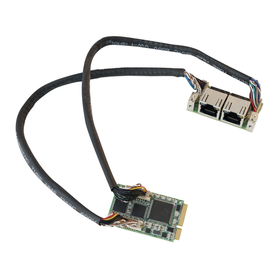
Introduction Overview MEC-LAN-M002 is an Ethernet card for embedded PC. The card follows the Mini PCI-e standard which is compliant with PCI Express x 1 classification and small form factor (30×50.95 mm). This board fits in any host computer that has mini express card slots. -
Page 5: Installation Flowchart
Installation Flowchart Installation Flowchart of MEC-LAN-M002 The following flowchart provides a brief summary of the procedure you should follow to install the Mini PCI-e card: Hardware Installation Connect the internal cable Hardware Installation Install the card in the Mini PCI-e slot... -
Page 6: Hardware Installation
Hardware Installation This chapter describes the PCI Express Series hardware installation procedure. Since the BIOS automatically assign the PCI Express board’s IRQ number and I/O addresses, you must plug in the board before installing the driver. Step 1 Connect the internal cable to the card Both sides of the cable connectors are the same, it doesn’t matter which side Note you connect... - Page 7 Step 2 Install the card to the Mini PCI-e slot Make sure you install the card in the right position (fool-proof design) Step 3 Fix the card on the motherboard (clip type or screw type) There are 2 options to fix the card. It depends on the design of the motherboard (clip or screw).
- Page 8 Step 4 Card installation completed Connect other side of the cable to the daughter board Step 5 Connect the cable to the daughter board Connect other side of the cable to the daughter board Both sides of the cable connectors are the same, it doesn’t matter which side Note you connect...
- Page 9 Connector Fixation MECFIX – Versatile Mounting 1. Standard PCI/PCIe Bracket PCI / PCIe IO Bracket 2. Low Profile PCI/PCIe Bracket Low Profile IO Bracket...
- Page 10 3. Internal Mounting Upper Fixation – Industrial System Right & Left Fixation – Industrial System...
- Page 11 4. Customized Front / Rear Plate Front / Rear I/O Plate Universal Bracket...
-
Page 12: Software Installation
Software Installation This chapter gives installation, configuration, and update/removal procedures for the driver for Win 2003, Win XP, Win Vista, Win 7, and Win 8. Step 1 Turn on PC and start Windows Note XP OS as example... - Page 13 Step 2 Windows automatically detects the new device If the card is installed properly, system would detect the new device and the hardware wizard would start automatically. Click “Cancel” to disregard Step 3 Insert CD Open the CD drive...
- Page 14 Find the “MEC-LAN-M002” folder Step 4 Open the “MEC-LAN-M002” file folder Find the “Driver” folder Step 5 Open the “Driver” folder...
- Page 15 Step 6 Find the appointed OS folder (Ex.: XP) Open the appointed OS folder (We use XP as an example in the above picture) Make sure you select the correct OS Step 7 Find your OS version (Ex.: XP 32bit) Select appoint OS folder (We use XP 32bit as an example in the above picture) Make sure you select the correct version of the OS (Ex.: 32-bit or 64-bit)
- Page 16 Step 8 Open and Run Driver file 1. Open the driver file 2. Systems starts auto run Step 9 System starts auto run System extracts the file and starts installation automatically...
- Page 17 Step 10 Driver installation set up Click “Next” Step 11 License Agreement Select “I accept the terms in the license agreement” Click “Next”...
- Page 18 Step 12 Driver setup options Select the drivers Click “Next” If you are not sure which driver you want to install, keep the default setting and Note click “Next”. Step 13 Start driver installation Click “Install”...
- Page 19 Step 14 Driver installation completed Driver install is completed, click “Finish” Step 15 Confirm if driver is installed Start “Computer Management” program → → → Go to the route: My Computer Manage Device Manager Network adapters You would find driver name: 2x Intel® 82583V Gigabit Network Connection Device is ready to be used...
-
Page 20: Appendix
Appendix Pin Assignments ... -
Page 21: Board Side Pin Assignments
Board Side Pin Assignments Wire to Board Connector (CN1、CN5) Description Description BI_DA1+ BI_DD1+ BI_DA1- BI_DD1- BI_DB1+ +1.8V BI_DB1- BI_DC1+ Link100_1 BI_DC1- Link1000_1 Active_1 Link_1 Wire to Board Connector (CN2、CN6) Description Description BI_DA2+ BI_DD2+ BI_DA2- BI_DD2- BI_DB2+ +1.8V BI_DB2- BI_DC2+ Link100_2 BI_DC2- Link1000_2 Active_2... -
Page 22: Device Side Pin Assignments
Device Side Pin Assignments Ethernet Connector (CN3、CN4) Description Description BI_DA1+ BI_DA2+ BI_DA1- BI_DA2- BI_DB1+ BI_DB2+ BI_DC1+ BI_DC2+ BI_DC1- BI_DC2- BI_DB1- BI_DB2- BI_DD1+ BI_DD2+ BI_DD1- BI_DD2-... -
Page 23: Technical Reference
Technical Reference MEC-LAN-M002 Specifications General PCI-Express Revision PCI-Express Base Specification Rev 1.1 PCI-Express Electromechanical PCI-Express Mini Card Electromechanical Rev. 1.1 Revision Hardware Controllers Intel 82583V x 2 Single-Lane (x1) PCI-Express with throughput up to 2.5Gbps Interface (Connector) Ethernet 10/100/1000... -
Page 24: Mec-Lan-M002 Dimensions
MEC-LAN-M002 Dimensions MEC-LAN-M002 Daughter Board Dimensions... -
Page 25: Product Warranty Statement
Limitation of Liability Cervoz’ liability arising out of the manufacture, sale, or supplying of the product and its use, whether based on warranty, contract, negligence, product liability, or otherwise, shall not exceed the original selling price of the product. The remedies provided herein are the customer’s sole and exclusive remedies.
Need help?
Do you have a question about the MEC-LAN-M002 and is the answer not in the manual?
Questions and answers