
Related Manuals for FB Jets Dolphin S


Summary of Contents for FB Jets Dolphin S
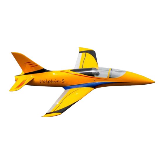
- Page 1 FB Jets Dolphin S FB Jets / Feibao Dolphin S Assembly Manual Written By Rich Miller in Collaboration with Fei Bao Jets Cover Photos by Robert J. Engle Rev. 0...
-
Page 2: Table Of Contents
FB Jets Dolphin S Contents DISCLAIMER: Introduction Specifications Component Size (Length) Adhesives Standard Pneumatic LG Systems Optional Electric LG Systems Parts List: Optional Equipment Additional Equipment Optional Equipment (Builders choice) Servo List (Hi-Tec) based on 6V torque specifications Servo List (JR) based on 6V torque specifications... - Page 3 FB Jets Dolphin S Step 15: Radio Channel Assignments Step 16: C.G. Step 17: Setting of throws Maintenance Tips: Annex A Drawings...
-
Page 4: Disclaimer
Note: In the USA it is mandatory that you belong to the Academy of Model Aeronautics and hold a valid Turbine Waiver, please check the local governing rules for operation of R/C model jets of your location before flying. Congratulations on your purchase of the FB Jets Dolphin S... -
Page 5: Introduction
You have chosen a model that represents the pinnacle of ARF technology and factory testing with the new manufacturing processes implemented by FB Jets. While there is not a lot of building to do, there is enough to keep you busy for quite a few evenings. Even if you have assembled other ARF jets, we highly recommend following the assembly sequence and procedures presented in this manual. - Page 6 FB Jets Dolphin S The wings utilize one carbon fiber main spar and have two anti-rotation pins, with one towards the front and one towards the rear of the root rib. The main spar has a 4 mm tapped hole in each outer end, there is a hole location in of the wings that accepts a flat head 4 mm bolt to secure the wing spar, location shown in photo.
-
Page 7: Specifications
FB Jets Dolphin S Specifications Total Length: 92 1/8” (2340 mm) Total Wingspan: 81 5/8" (2073 mm) C.G. Location 28% MAC: 10 1/2” (267 mm) from LE of Wing Prototype Dry Weight with all components: 30 lbs (13.6 Kg) Thrust Class: 22 to 36 lbs (100N to 160N) “Jet Central Cheetah used in prototype”... -
Page 8: Adhesives
Pneumatic retracts typically are the number one maintenance issue with most models however with proper installation procedures and preventive maintenance this need not be the case. The Dolphin S uses pneumatic retract and brakes. If you follow a few tips you should have a very reliable leak free operation. -
Page 9: Optional Equipment
FB Jets Dolphin S • 79” (200cm) Blue Air Line • 79” (200cm) Red Air Line • 79” (200cm) White Air Line • 79” (200cm) Yellow Air Line • 3 Three port valves (Gear & Doors) • 1 One Port Valve (Brakes) •... -
Page 10: Servo List (Hi-Tec) Based On 6V Torque Specifications
The order of construction may be changed to suit your personal preference; however, due to the size of the Dolphin S it is recommended to complete as much of the work as possible on the individual components before the final assembly. The majority of the assembly takes place in the forward fuselage section. -
Page 11: Pneumatic Landing Gear
FB Jets Dolphin S Fuselage Center Root section Wing Root section Note: any fiberglass surfaces on the inside of the airframe that requires components to be bonded should be cleaned with mild detergent and water to make sure that any mold release agent is removed, and then scuffed with medium grit sandpaper in the area of the intended bond to promote adhesion prior to applying the adhesive. -
Page 12: Step 2: Main Landing Gear
FB Jets Dolphin S Using a receiver or servo driver find servo neutral and attach a suitable double sided servo arm perpendicular to the servo making sure to tighten the servo arm screw. The threaded rod supplied with the kit was 2-56 style all thread and clevises as shown in the photos, it recommended to change these to 4-40 parts. -
Page 13: Step 3: Forward Fuselage
The Dolphin S is supplied with brass airline connectors, the prototype used the male end of the fittings glued into the fuselage at the wing junction for easy wing connections. -
Page 14: Optional Battery Box
FB Jets Dolphin S Optional Battery Box The prototype was constructed using two lite plywood battery boxes; these allow quick removal of Li-Po batteries for charging and maintenance and provide a method for achieving correct C.G. balancing without the need for added dead weight. The components can be cut from the templates in Annex A from 1/8”... - Page 15 FB Jets Dolphin S developed in the fuel system. All fuel system lines should be properly inserted onto the tubing and safety wire tied to prevent unwanted and potentially harmful leaks. Note: Restriction in the fuel system may cause performance issue with your turbine such as not allowing proper full speed RPM, abnormally high pump pulse width numbers and or excessive stress placed on the tanks while fueling the model.
-
Page 16: Tank Assembly
FB Jets Dolphin S Tank Assembly When working with brass tubing components please follow the steps outlined below: Use a small, round file or a #11 X-acto knife to remove the excess metal inside of the cut ends of the tubes. You will need to inspect the ends of all tubes. Another good method is to use a countersink tool to de-burr the tubing, as you want to create an internal chamfer. -
Page 17: Tank Mounting
FB Jets Dolphin S Tank Mounting It is recommended that the fuel tanks are mounted to allow for removal for future maintenance. There are many methods available to secure the tanks, a few include mounting with adhesive backed Velcro™ or tack glue using a few dobs of RTV. - Page 18 FB Jets Dolphin S UAT / Optional Smoke Tank Tray The tray features an integral UAT holder and provides a surface to mount an optional smoke tank. The plywood tank holders shown can be fabricated from the supplied template in Annex A utilizing 1/8”...
- Page 19 FB Jets Dolphin S Front Saddle Tank Mount Main tank brackets & UAT / (Smoke Tank) Tray...
-
Page 20: Step 5: Final Fuel System Plumbing
FB Jets Dolphin S The main tank mounts and UAT tray (Smoke Tank Mounting tray) can be fabricated from the supplied templates in annex X utilizing 1/8” (3mm) plywood. Trial fit the main tank as shown previously in the above photo sequence, mark the area on... -
Page 21: Step 6: Air Tank Installation
FB Jets Dolphin S Step 6: Air Tank Installation The air tanks can be installed in various locations in the airframe, the location used in the prototype was in the area below the front tray using formers cut from 1/8 (3mm) plywood) see photo. There are many methods available to secure the air tanks, a few include mounting with adhesive backed Velcro™... -
Page 22: Step 8: Wing - Servo Installation
FB Jets Dolphin S Step 8: Wing – Servo Installation The two wing halves are supplied with two pre-slotted servo hatches, eight “L” mounting brackets, and mounting hardware. The Flaps and Ailerons have slots pre-cut into the surface for the fiberglass control horn. - Page 23 FB Jets Dolphin S It is not recommended to use the rubber grommets supplied with the servo for the mounting into jet airframes as vibrations typically associated with reciprocating power plants are not an issue. Using a receiver or servo driver, find servo neutral and attach a suitable single sided servo arm perpendicular to the servo making sure to tighten the servo arm screw.
-
Page 24: Step 9: Vertical Fin And Rudder Servo Installation
FB Jets Dolphin S Step 9: Vertical fin and rudder servo installation Production models have the servo slots and the control horn slots precut as shown The servo is installed in the fin with the spline of the rudder servo facing towards the base of the fin and closest to the leading edge. -
Page 25: Step 10: Horizontal Stabilizer And Elevator Servo Installation
FB Jets Dolphin S Assemble the rudder linkage; the linkage should measure 4.5” (114 mm) in length from center to center of the ball link and clevis. The clevis should be connected to the hole in the horn that is ¾” (19 mm) from center of the spline. - Page 26 FB Jets Dolphin S adhesive should be removed. Let the control horn adhesive setup undisturbed before proceeding. Using a receiver or servo driver, find servo neutral and attach a suitable single sided servo arm perpendicular to the servo making sure to tighten the servo arm screw.
-
Page 27: Front Equipment Tray
FB Jets Dolphin S Airline connectors located in fuselage root section along with builder supplied D-type servo connector. Front equipment tray Location for electronic solenoid valves under front tray Plywood pads glued into place Tray secured to pads... -
Page 28: Step 12: Turbine Mounting Rails And Tail Pipe
FB Jets Dolphin S Step 12: Turbine Mounting Rails and Tail Pipe Vacuum the fuselage thoroughly to remove any debris before installing the turbine. If you need to trim anything for turbine clearance, use a vacuum while you work. This will reduce the chance of having foreign objects finding their way into your turbine, remember to always use a FOD screen. -
Page 29: Step 14: Cockpit
FB Jets Dolphin S Step 14: Cockpit The optional semi scale cockpit tub comes pre-trimmed and painted along with the preinstalled canopy glass to the frame. Check fit of canopy frame to fuselage, adjust fitment where required, the canopy latch should engage with little effort when fitment is correct. -
Page 30: Step 15: Radio Channel Assignments
FB Jets Dolphin S Step 15: Radio Channel Assignments The prototype was set up utilizing 11 channels as follows, many radio system and option exist, it is up to the builder’s discretion to pick the equipment that best fits their particular needs:... -
Page 31: Step 17: Setting Of Throws
Note do not charge LiPo batteries while installed in the airframe, the battery boxes provide easy removal of batteries for charging. Congratulations, you have completed construction of your Fei Bao Dolphin S... -
Page 32: Annex A Drawings
Annex A Drawings FB Jets Dolphin S... - Page 33 Annex A Drawings FB Jets Dolphin S...
- Page 34 Annex A Drawings FB Jets Dolphin S...
- Page 35 Annex A Drawings FB Jets Dolphin S...
- Page 36 Annex A Drawings FB Jets Dolphin S...
- Page 37 Annex A Drawings FB Jets Dolphin S...
- Page 38 Annex A Drawings FB Jets Dolphin S...
- Page 39 Annex A Drawings FB Jets Dolphin S...
Need help?
Do you have a question about the Dolphin S and is the answer not in the manual?
Questions and answers