
Related Manuals for FB Jets FEI BAO


Summary of Contents for FB Jets FEI BAO
- Page 1 F E I B A O R A F A L E FEI BAO JETS Rafale Assembly Manual Written By Rich Miller In collaboration with R/C Jet Models...
- Page 2 Turbine Waiver, please check the local governing rules for operation of R/C model jets of your location before flying. Congratulations on your purchase of the Fei Bao Rafale. Introduction: You have chosen a model that represents the pinnacle of ARF technology. While there is not a lot of building to do, there is enough to keep you busy for a few evenings.
- Page 3 Pneumatic retracts typically are the number one maintenance issue with most models however with proper installation procedures and preventive maintenance this need not be the case. All Fei Bao jets uses pneumatic gear doors, retracts and brakes. If you follow a few tips you should have a very reliable leak free operation.
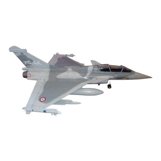
- Page 4 Full Scale Specifications: Length: 50.20ft (15.30m) Width: 35.76ft (10.90m) Height: 17.52ft (5.34m) Performance: Max Speed: 1,320mph (2,125kmh; 1,147kts) Max Range: 1,150miles (1,850km) Climb Rate: Not Available Ceiling: 55,118ft (16,800m; 10.4miles) Hard points: 14 (including two wingtip mounts) Empty Weight: 19,974lbs (9,060kg) MTOW: 47,399lbs (21,500kg) Engine(s): 2 x SNECMA M88-2 augmented turbofan engines with afterburning generating 19,555lbs of thrust.
- Page 5 Recommended Servo List (JR) • Canard: (1) 8611a • Elevons: (2) • Rudder: (1) 3421 • Nose Steering: (1) 2721 • Retracts: (1) 351 or equivalent • Brakes: (1) 351 or equivalent Recommended Servo List (Hi-Tec) • Canard: (1) HS-645MG or HS-5645MG •...
- Page 6 Photo 1 There is no structure for the hinge points to mount to in the Elevon section therefore hardwood balsa sections must be glued into place and then drilled for the hinge points as show in photos 2 and 3. Start by making the two extra holes in the leading edge of the surface;...
- Page 7 Photo 3 Photo 4 Photo 5 Photo 6 Next the position of the new hinges needs to be transferred to the trailing edge of the wing. Drill the two additional holes for the new hinge locations. As in the case of the surfaces there is no structure in the TE of the wing at the new hinge point locations.
- Page 8 Position your servo in the wing pocket and then take a straight edge and create the line from the servo arm to the horn location on the surface. Mark the horn position on the tape that is on the surface, this will now serve as the slot guide. When cutting the slot into the surface great care should be taken as not to cut into the LE structure of the surface, cutting the LE material could cause a failure of the surface in flight.
- Page 9 Wing Servo Mounting: The production kit that was used for this manual had the servo bay cut outs position far back towards the TE of the wing; this creates a height issue when using standard sized servos and the stock flat hatches; see Photo 9. Photo 9 The kit was also supplied with extra raised hatches to help solve this issue.
- Page 10 Note: If you kit is supplied with the factory positioned servo bays located back towards the TE of the wing (see Photo 11) then the plywood mounts may require some modifications in order to mount the servo of your choice. Due to the large surface of the Elevon it is recommended to use a standard size digital servo with metal gears which will supply plenty of reserve torque.
- Page 11 Locate and prepare the area on the wing for the mounting blocks for the linkage covers, see photo 13, glue blocks in place; after the adhesive cures mount linkage covers with small wood screws. Photo 13 Repeat procedure for the other wing. Be sure to keep the linkage lengths equal. Step 2A: Vertical Fin and Rudder This manual will provide two options for mounting the rudder servo, the first one will be the factory intended method (concealed), and the second will be the author’s alternative method.
- Page 12 1.18” (30 m Pin that will be glued into the above hole, the small end faces down, insert pin up to the Photo 15 shoulder. Start by gluing the three hinge points to the fin, after they have cured then glue the hinge points to the rudder, see photo 14.
- Page 13 Note: It is the authors practice not to use the rubber grommets as supplied with the servo for mounting servos in jet airframes as vibrations are not an issue. Align the servo shaft by using your receiver or servo driver to find the servos neutral point and then attach the heavy-duty servo arm with the arm placed as shown in Photo 17.
- Page 14 Photo 20 Photo 21 Check for free movement of the rudder, insert the vertical fin into fuselage and verify operation using your receiver or a servo driver, see photo 21. If the rudder movement is satisfactory then permanently mount fin to fuselage by tightening the rear clamping bolt and inserting the front pin bolt and washer, see photos 22 &...
- Page 15 Fin Clamp Bolt Hole Photo 22 Photo 23 STEP 2B: Alternate Vertical Fin Servo Mounting Method The alternate method for installing the rudder servo is directly in the vertical fin, this method provides for the use of a traditional linkage arrangement. The advantage of this system is increase rudder deflection and less chance of surface flutter.
- Page 16 Servo Fixture Blocks that will be glued into place Photo 25 Photo 26 After prepping the fin, make sure to scuff the inner surface with medium grit sand paper, glue in the mock up servo fixture with the mounting blocks as shown in photo 27. Make sure not to get glue on the mock up servo fixture or it will be difficult to remove later.
- Page 17 Photo 27 After adhesive is dry remove fixture. The servo installs with the top of the servo mounting tabs making contact with the servo rails, if the servo has reinforcement on the top tab it may need to be removed so the servo will sit flush on the mounts. The servo spline faces the front of fin.
- Page 18 Photo 29 Photo 30 Assemble the rudder linkage; you may need to enlarge the hole in the control horn with a 7/64 inch drill for the connecting bolt bolt. Do not over tighten this bolt as the rod will bind as the rudder is actuated.
- Page 19 Step 3: Air Tank Installation The air tanks can be installed in various locations in the airframe, the location I choose was in the area between the canopy and the rear hatch, see photo 35. There are many methods available to secure the air tanks, a few include mounting with adhesive backed Velcro™, permanently glued in with Goop™, or mounted to a tray with Velcro™...
- Page 20 Photo 34 Photo 35 Photo 36...
- Page 21 Step 4: Fuel System If your model is provided with a factory plumbed fuel system it is recommended that you disassemble and inspect the tank hardware. The process used to cut the tubes at the factory may leave behind a ridge that constricts fuel flow and could result in excess tank pressure / restriction and leakage.
- Page 22 Photo 40 If you are using the factory installed fuel tank components please follow the step outlined below: Loosen the Philips head screw and remove the stopper assembly from the tank. Use a small, round Perma-Grit rat tail file or an X-acto knife to remove the excess metal inside of the cut ends of the tubes.
- Page 23 Photo 41 Spacer Block mounts underside in this area Velcro Strap Photo 42 Spacer block glued under center of tank mounting plate prior to gluing plate to fuselage Position the main tank and apply a Velcro hold down strap, see photo 43. Photo 43 Use Velcro Strap around main tank...
- Page 24 Photo 44 Photo 45 The plywood tank holders shown in photo 46 can be fabricated from the supplied template and plywood to hold the saddle tanks in position after the engine rails are repositioned. Photo 46 Saddle Tank positioning plates For a parallel saddle tank system connect two pieces of fuel tubing approximately 6”...
- Page 25 (200 mm) should be sufficient. Connect the vent from the saddle tanks to a bulkhead vent fitting located on the bottom of the fuselage, the fitting should be located between on of the intake ports to provide protection in case of a gear up landing, see photo 47. Photo 47 Connect a length of tubing that will run to UAT to the fuel pickup tube on the main center tank.
- Page 26 Step 5: Nose Gear Door and Cylinder Installation Note: If your model came with factory installed gear doors skip this step. The order in which the doors are installed is up to the builder; this manual will start with the front single door, and then proceed to the two double doors.
- Page 27 Photo 49 Photo 50 Photo 51...
- Page 28 Photo 52 Photo 53 Photo 54...
- Page 29 Photo 55 Photo 56 Spacer...
- Page 30 Step 6: Main doors If required cut out main gear openings with a Dremel cutoff wheel or other appropriate means to allow for gear door installation. Make sure that a lip is remaining after the final sanding to size is completed, see photos 57. The doors may require some minor trimming to fit the fuselage opening, make any adjustments that are required during the fit up of the doors.
- Page 31 Photo 58 Photo 59 Photo 60...
- Page 32 Photo 61 Photo 62 Photo 63...
- Page 33 Photo 64 Locating Cylinder Photo 65 Step 7: Nose Retract Unit Installation Before installing the nose retract assembly, remove the strut set screws one at a time and apply Loctite then reassemble making sure that the set screws are snug. Attach air lines and test the retract unit with a hand pump, making sure it will hold air and operates smoothly, check for air leaks in a container filled with water see photo 66.
-
Page 34: Photo
To ensure tangle free operation of the pull-pull cable system Du-Bro heavy duty E/Z connectors (see photo 67) were used to hold the steering cables to the tiller arm. The advantage of this setup is it allows the cables to rotate easily when the nose wheel is retracted. - Page 35 Check for clearance Photo 70 Position the nose retract unit into the retract plate from the bottom. The front of the retract unit should be positioned as shown in photo 70, make sure to check the tiller arm clearance between the mount, this can be done by moving the retract from up to down position by hand.
- Page 36 Photo 72 Step 8: Main Landing Gear Photo 73 Install airlines on the retract units. Check for air leaks and smooth operation of the retracts with a hand pump as done in section 7, see photo 66. Install main struts into the door retract cylinders. Working carefully to make sure the retract unit stays in this position and aligned equally to either side of the gear opening, drill one of the holes closest to the forward former.
- Page 37 When all four holes are drilled and you are satisfied with the alignment, remove the retract unit. 4-40 Allen head bolts and blind nuts were used for this build; drill out each hole to be large enough for the blind nut. Insert these from the top and snug them down with one of the bolts.
- Page 38 Photo 74 Airline Connections Step 10: Nose Gear Steering & Joining the Fuselage Nose Section Installation of equipment is up to the builder’s discretion as many options exist. The factory supplied position of the steering servo was in the front equipment tray; however this location proved to increase the amount of servo torque required for steering, it was decided to fabricate a new servo mount to position the steering cables in a straight line from the tiller arm, The new mount was placed into the nose section, see photo 75.
- Page 39 Photo 76 Photo 77 Photo 78...
- Page 40 Photo 79 Photo 80...
- Page 41 Photo 81 Make the final steering cable connections as shown in photo 81. Step 11: Component Board There are a vast amount of possibilities for mounting equipment into your airframe so the following is one suggested method. Remember to allow room for the cockpit tubs to sit into the airframe without interference from tall components on the component board.
- Page 42 Photo 82 Photo 83...
- Page 43 Addition component locations for ancillary devices such as the gear door sequencer, receiver, voltage regulator and ECU to name a few can be done using mounting plates glued to the fuselage in positions where space allows. Slots cut into the plates allow for the use of Velcro strapping to hold the components, see photos 84 through 87.
- Page 44 Photo 87 For areas under the front component tray make sure to keep the clear of wires and airlines for retraction of the steering servo. The nose wheels will fit right up against the bottom of the component board when retracted, so it is recommended you have nothing extending below the board in this area.
- Page 45 Photo 88 Photo 89...
- Page 46 Photo 90 Rear Tray Brace 4-40 Blind Nuts on bottom of cross Front Mount Doubler brace Rear Tray Mounting Screw Photo 91...
- Page 47 Step 13: Engine Rails, Bypass and Pipe Clean the fuselage thoroughly before installing the engine. If you need to trim the intake for engine clearance, use a vacuum while you work. This will reduce the chance of having a foreign object finding its way into your engine. It is the builders choice as to use the supplied full bypass for your installation;...
- Page 48 Connect fuel, gas and electrical lines up to the turbine following engine manufacturer’s recommendations. Bell mouth If the Bypass is not used then you will need to purchase a bell mouth that will be used to hold the shape of the pipe inlet, attach as per the manufacturers recommendations, see photo 93 Photo 93 Step 14: Engine Accessories...
- Page 49 Photo 94 Photo 95 Photo 96...
- Page 50 Step 15: Cockpit The cockpit tubs come pre-trimmed and painted with a gloss black finish and should simply drop into place; if desired you can paint the tubs with flat black or grey. The canopy also comes pre-fit at the factory and should be latched in place. You can glue the tubs to the canopy if desired.
- Page 51 Step 18: Radio Programming The prototype was set up utilizing 8 channels as follows using a Futaba 9C, many radio system and option exist, it is up to the builder’s discretion to pick the equipment that best fits the their needs: Ch 1 Elevon (Elevon mix enabled) CH 2 Elevon (Elevon mix enabled)
- Page 52 Photo 100 Elevon (Elevator Function) should be set to 18 mm up/down as measured from the center line of the missile rail. Elevon (Aileron Function) should be set to 8 mm up/down for high rate and 3mm up/down for low rate. The Rafale require reflex to be programmed, i.e. the bottom edge of the Elevon should be set to be slightly below the bottom edge of the missile rail (if installed) or wing tip.
- Page 53 Maintenance Tips: Inspect the door cylinder bolts and hinges each time you mount the wing. When inverting the aircraft, put a short piece of fuel tube with a plug on the drain fitting. Cycle the gears before each flying session, checking for binding and proper door operation. Check the struts for play, indicating the clamping set screw needs to be tightened, verify toe in on main wheels for reliable tracking.
- Page 54 Congratulations, you have completed construction of your Fei Bao Rafale...
Need help?
Do you have a question about the FEI BAO and is the answer not in the manual?
Questions and answers