Table of Contents

Related Manuals for Charles C-Charger 5000


Summary of Contents for Charles C-Charger 5000
-
Page 1: Installation Instructions
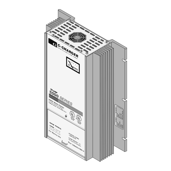
LT93−12405E−1 Issue 1 Print 5 INSTALLATION INSTRUCTIONS C-CHARGER & OWNER’S MANUAL MARINE ELECTRONIC BATTERY CHARGER 40-, 50-, & 60-Amp 5000 Series Marine Group E Charles Industries, Ltd. All rights reserved. Printed in the United States of America. -
Page 2: Table Of Contents
................E Charles Industries, Ltd. All rights reserved. Printed in the United States of America. -
Page 3: Introducing
Manual Purpose With your personal safety in mind, this manual lists important safety precautions first, then covers installation, operation, maintenance, troubleshooting and warranty and customer service information. E Charles Industries, Ltd. All rights reserved. Printed in the United States of America. -
Page 4: Important Safety Instructions
Do not expose the C-Charger to rain, snow, or excessive moisture. C-Charger Application Precaution These units are intended for hard-wired applications. Use of attachments not recommended or sold by Charles Marine Products may result in risk of fire, electrical shock or personal injury. -
Page 5: Preparing To Charge Precautions
équipement utilisé près des batteries. Consultez les mises en garde inscrites sur ces produits et sur le moteur. E Charles Industries, Ltd. All rights reserved. Printed in the United States of America. -
Page 6: Mises En Garde Importantes (Safety Instructions In French)
N’exposez pas le C-Charger à la pluie, à la neige, ou à l’humidité excessive. Applications recommandées Ces appareils sont conçus pour les applications locales permanentes. L’utilisation d’accessoires non recomman- dés ni vendus par Charles Marine Products présente des risques d’incendie, de chocs électriques ou de bles- sures. C-Charger endommagé... - Page 7 à la terre (GRN) du C-Charger, à l’aide des passe-fils. 2. Les connections au C-Charger doivent être conformes à tous les codes et ordonnances locaux. E Charles Industries, Ltd. All rights reserved. Printed in the United States of America.
-
Page 8: Installing The C-Charger
Confirm the intended battery type with the model number on the product identification label located on the C-Charger (refer to Table 1). All C-Chargers have been factory preset. If your C-Charger model does not match your intended battery type, contact Charles Marine Customer Service at 847/806-6300 for further assistance. Choosing Mounting Location The C-Charger should be mounted vertically flush on a bulkhead in a protected area away from rain or spray and as close to the batteries as possible. -
Page 9: Choosing Wire Gauge
After determining the wire lengths and gauges, make the AC wiring connections to TB1. (Refer to the Block Dia- gram in Figure 1.) Use spade terminals, and torque the screws to 8 +/−1 inch/pounds. To make connections to the terminal blocks: E Charles Industries, Ltd. All rights reserved. Printed in the United States of America. -
Page 10: Making Dc Connections On Terminal Block 2 (Tb2)
5. Internal fuse size is for 40-amp model. See Table 4 for 50- and 60-amp model fuse sizes. Figure 1. 40-, 50- and 60-Amp 5000 Series Block Diagram E Charles Industries, Ltd. All rights reserved. Printed in the United States of America. -
Page 11: Installing External Fuse (Not Supplied)
(See Table 4). Before reapplying power, pull down the access door to close it. Once down, secure the access door to the top cover with the small screw provided. E Charles Industries, Ltd. All rights reserved. Printed in the United States of America. -
Page 12: Maintaining The C-Charger
13.5 and 15 volts DC. Should the unit still be inoperable after all tests have been completed in sequence, refer to the section in this manual on Warranty & Customer Service. E Charles Industries, Ltd. All rights reserved. Printed in the United States of America. -
Page 13: Warranty & Customer Service
WARRANTY & CUSTOMER SERVICE Warranty The CHARLES Marine & Industrial Group warrants the unit will be free from defects in materials and workman- ship that cause mechanical failure for five (5) years, as set forth in the Limited Warranty. Notice of any alleged defect in material or workmanship must be provided within thirty (30) days of discovering the problem, and within the warranty period. -
Page 14: Specifications
120 VAC nom 120 VAC nom 220 VAC nom 220 VAC nom *See the label on the side of the charger for the operating voltage. g g g E Charles Industries, Ltd. All rights reserved. Printed in the United States of America.
Need help?
Do you have a question about the C-Charger 5000 and is the answer not in the manual?
Questions and answers
"charles 30 amp battery charger 5000 sp series 12 voc" I would like to request information about the dimensions of the **** in this device and its voltage, as I need to replace it on my end
The Charles C-Charger 5000 has the following dimensions:
- Height: 13.25 in. (33.7 cm) or 15.25 in. (38.7 cm) depending on the model
- Width: 9.5 in. (24.1 cm)
- Depth: 3.7 in. (9.4 cm)
The operating voltage options are:
- 120 VAC nominal
- 220 VAC nominal (Check the label on the side of the charger for specific operating voltage).
This answer is automatically generated