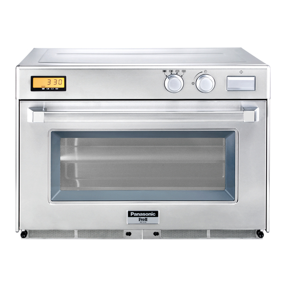
Panasonic NE-3280 Service Manual
Hide thumbs
Also See for NE-3280:
- Service manual (55 pages) ,
- Operating instructions manual (28 pages) ,
- Technical bulletin (2 pages)
Table of Contents
Advertisement
Advertisement
Table of Contents
Troubleshooting

Related Manuals for Panasonic NE-3280


Summary of Contents for Panasonic NE-3280
- Page 1 09/2012 Mod: NE3240 Production code: NE3240...
- Page 2 ORDER NO. MOD0108245C2 Microwave Oven NE-3280 / NE-3240 / NE-2180 / NE-2140 SPECIFICATIONS 2001 Matsushita Electric Industrial Co., Ltd. All rights reserved. Unauthorized copying and distribution is a violation of law. Created with novaPDF Printer (www.novaPDF.com). Please register to remove this message.
-
Page 3: Outline Diagram
1. OUTLINE DIAGRAM Created with novaPDF Printer (www.novaPDF.com). Please register to remove this message. - Page 4 2. OPERATION PROCEDURE (NE-3280/2180) Created with novaPDF Printer (www.novaPDF.com). Please register to remove this message.
- Page 5 Created with novaPDF Printer (www.novaPDF.com). Please register to remove this message.
- Page 6 Created with novaPDF Printer (www.novaPDF.com). Please register to remove this message.
- Page 7 3. OPERATION PROCEDURE (NE-3240/2140) Created with novaPDF Printer (www.novaPDF.com). Please register to remove this message.
- Page 8 4. SCHEMATIC DIAGRAM NE-3280 Created with novaPDF Printer (www.novaPDF.com). Please register to remove this message.
- Page 9 5. SCHEMATIC DIAGRAM NE-3240 Created with novaPDF Printer (www.novaPDF.com). Please register to remove this message.
- Page 10 6. SCHEMATIC DIAGRAM NE-2180 Created with novaPDF Printer (www.novaPDF.com). Please register to remove this message.
- Page 11 7. SCHEMATIC DIAGRAM NE-2140 Created with novaPDF Printer (www.novaPDF.com). Please register to remove this message.
- Page 12 8. WIRING DIAGRAM NE-3280 Created with novaPDF Printer (www.novaPDF.com). Please register to remove this message.
- Page 13 9. WIRING DIAGRAM NE-3240 Created with novaPDF Printer (www.novaPDF.com). Please register to remove this message.
- Page 14 10. WIRING DIAGRAM NE-2180 Created with novaPDF Printer (www.novaPDF.com). Please register to remove this message.
- Page 15 11. WIRING DIAGRAM NE-2140 Created with novaPDF Printer (www.novaPDF.com). Please register to remove this message.
-
Page 16: Description Of Operating Sequence
12. DESCRIPTION OF OPERATING SEQUENCE Variable power cooking control The coil of power relays are energized intermittently by the digital programmer circuit, when the oven is set at any power selection except for High power position. The digital programmer circuit controls the ON-OFF time of the power relays contacts in order to vary the output power of the microwave oven. - Page 17 12.1. Defrost control When defrost power and defrosting time is selected and Start pad is touched: 1. The digital programmer circuit (DPC) divides the total defrosting time into 8 equal periods, consisting of four defrosting periods, each followed by a standing period.(See figure) 2.
-
Page 18: Cautions To Be Observed When Troubleshooting
13. CAUTIONS TO BE OBSERVED WHEN TROUBLESHOOTING Unlike many other appliances, the microwave oven is high voltage, high current equipment. Though it is free from danger in ordinary use, extreme care should be taken during repair. CAUTION Servicemen should remove their watches whenever working close to or replacing the magnetron. -
Page 19: Confirm After Repair
Important Note 1. High voltage above 250 volts are existing on following parts during operation. -Magnetron -High Voltage Transformer -High Voltage Diode -High Voltage Capacitor Unusual attention should be paid during repair or troubleshooting of product. 2. If the microwave oven is operated with incorrect installed door hinge or magnetron, it can cause microwave leakage of over 5mW/square centime-ter. -
Page 20: Disassembly And Parts Replacement Procedure
Never insert a wire, nail or any other metal object through the lamp holes on the cavity or any other holes or gaps, because such objects may work as an antenna and cause microwave leakage. 13.7. CAUTION MICROWAVE RADIATION Personnel should not be exposed to the microwave energy which may radiate from the magnetron or other microwave generating device if it is improperly used or connected all input and output... - Page 21 4. Remove the 4 screws holding magnetron. 5. Remove 2 screws holding thermal cutout. 6. Remove the air guide from magnetron and install it on the new magnetron. NOTE To prevent microwave leakage, tighten mounting screws properly making sure there is no gap between the waveguide and the magnetron.
- Page 22 14.2. Digital programmer circuit board 1. Remove grounding screw for membrane switch and D.P.C. ground. 2. Remove 2 screws holding control panel assembly to detach it from main unit then remove connectors. 3. Remove 2 screws holding the D.P.C. board and remove the board by freeing catch hooks.
- Page 23 carefully remove all solder from the terminal pins of the low voltage transformer and/or power relays. NOTE Do not use a soldering iron or desoldering tool of more than 30 watts on DPC contacts. 2. With all the terminal pins cleaned and separated from DPC contacts, remove the defective transformer/power relays and install new transformer/power relays making sure all terminal pins are inserted completely.
- Page 24 14.5. Upper antenna (Right and Left) Upper antenna (Right and Left) 1. Remove 8 plastic clips holding ceiling plate and exhaust guides by using flat screwdriver or the like. 2. Remove 2 screws holding upper antenna assy by inserting screwdriver through the opening on the antenna as shown in figure.
- Page 25 Created with novaPDF Printer (www.novaPDF.com). Please register to remove this message.
- Page 26 14.7. Replacement of temperature sensor (Thermal protector) 1. Cut 2 lead wires at the top of sensor terminals. 2. Remove 2 screws holding temp sensor and replace with new one. 3. Solder the lead wires securely to the sensor terminals. 14.8.
- Page 27 15. COMPONENT TEST PROCEDURE CAUTION 1. High voltage is present at the high voltage terminal of the high voltage transformer during any cook cycle. 2. It is neither necessary nor advisable to attempt measurement of the high voltage. 3. Before touching any oven components, or wiring, always unplug the oven from its power source and discharge the high voltage capacitor.
- Page 28 1. Isolate magnetron from the circuit by disconnecting the leads. 2. A continuity check across magnetron filament terminals should indicate one ohm or less. 3. A continuity check between each filament terminal and magnetron case should read open. 15.4. Diode 1.
- Page 29 of the diode, otherwise an infinite resistance may be read in both directions. A normal diode’s resistance will be infinite in one direction and several hundred k in the other direction. 15.5. Membrane key board (Membrane switch assembly) Check continuity between switch terminals, by tapping an appropriate pad on the key board. The contacts assignment of the respective pads on the key board is as shown in digital programmer circuit.
-
Page 30: Measurements And Adjustments
16. MEASUREMENTS AND ADJUSTMENTS 16.1. Adjustment of the safety switch B (Right and Left side) 1. Switch operation When the door is slightly opened, the safety switch B opens the main circuit. The movement of the door from the closed position to the operation position (shown as lier) of the switch when it opens the main circuit, must maintain within following tolerances. - Page 31 16.3. Adjustment of the safety switch A (Door switch) (Right and Left side) 1. Switch operation When the door is slightly opened, the contacts of safety switch A opened to give digital programmer circuit the information that the door is opened. The allowable movement of the door from the closed position to the operating position (shown as liter) of the switch when it opens the circuit, is specified as follows;...
-
Page 32: Measurement Of Microwave Output
The normal temperature rise (T2 — T1) at High power position for each models is as shown in following table. Model Temperature Rise / (1 liter — 1 Min.) NE-3280 / NE-3240 Min. 27.4°C NE-2180 / NE-2140 Min. 18°C Created with novaPDF Printer (www.novaPDF.com). Please register to remove this message. -
Page 33: Troubleshooting Guide
If the unit shows faulty symptom as shown below, check the parts listed in possible cause column depending on failure indication e.g. F81, F82 in the display. [TROUBLE] Oven does not operate at all or oven does not start cooking. NE-3280, NE-3240 Created with novaPDF Printer (www.novaPDF.com). Please register to remove this message. - Page 34 DISPLAY CONDITIONS POSSIBLE CAUSE TIMING OF FAILURE INDICATION 1. Temperature sensor failure Open temperature It is appeared when failure 2. Digital programmer circuit failure sensor (exhaust) occurred. 3. Loose connector CN5 1. Temperature sensor failure Short temperature It is appeared when failure 2.
-
Page 35: Exploded View And Parts List
DISPLAY CONDITIONS POSSIBLE CAUSE TIMING OF FAILURE INDICATION 1. Temperature sensor failure Open temperature It is appeared when failure 2. Digital programmer circuit failure sensor (exhaust) occurred. 3. Loose connector CN5 1. Temperature sensor failure Short temperature It is appeared when failure 2. - Page 36 Created with novaPDF Printer (www.novaPDF.com). Please register to remove this message.
-
Page 37: Parts List
19. PARTS LIST NOTE When ordering replacement part(s), please use part number(s) shown in this parts list. / Do not use description of the part. / Importan safety notice: / Components identified by mark have special characteristics important for safety. / When replacing any of these components, use only manufacturere’s specified parts. - Page 38 NE-3240,NE-2140,2180(4X12) / (FOR TERMINAL PLATE ANTENNA,MOTOR COVER, / SWITCH HOLDER,DIODE,CAPACITOR BRACKET, / ESCUTCHEON BASE,DPC EARTH) XYD4+EE12F SCREW NE-3280(FOR TERMINAL PLATE ANTENNA, / MOTOR COVER ,SWITCH HOLDER,DIODE, / CAPACITOR BRACKET,ESCUTCHEON BASE,DPC EARTH) XYD4+EE12F SCREW NE-3240,NE-2140,2180(4X12) / (FOR TERMINAL PLATE ANTENNA,MOTOR COVER, / SWITCH...
- Page 39 Pcs/Set Ref. No. Part No. Part Name & Description Remarks ANE0911000EH CUSHION RUBBER B NE-3280,NE-3240 ANE0911000EH CUSHION RUBBER B NE-2180,NE-2140 ANE0911000EH CUSHION RUBBER B NE-2180,NE-2140 ANE0911000MG CUSHION RUBBER B NE-3280,NE-3240 ANE0911000MG CUSHION RUBBER B NE-3280,NE-3240 ANE0917000EB CUSHION RUBBER B ANE0917000EB...
- Page 40 A16163060GP PANEL B(U) NE-2180 Created with novaPDF Printer (www.novaPDF.com). Please register to remove this message.
- Page 41 ANTENNA STOPPER A20193030GP ANTENNA STOPPER A20193030GP ANTENNA STOPPER A202R3560GP ANTENNA(U) A202R3560GP ANTENNA(U) A22173030GP BARRIER SHEET A A22183030GP BARRIER SHEET B NE-3280,NE-3240 A22183030GP BARRIER SHEET B NE-3280,NE-3240 A22193030GP BARRIER SHEET C NE-2180,NE-2140 NE-3280,NE-3240 A22193030GP BARRIER SHEET C ANE3008P00RN HINGE PIN ANE3008P00RN...
- Page 42 OVEN LAMP COVER A63903310GP H.V.CAPACITOR NE-2180,NE-2140(0.82MF, AC2300V) A63903330GP H.V.CAPACITOR NE-3280,NE-3240(1MF, AC2300V) A61073030GP PARTS BRACKET B ANE6142-F60 MICROSWITCH NE-3280,NE-2180 / V-15G-3C26(SECONDARY INTERLOCK SWITCH) A61423030GP MICROSWITCH NE-3240,NE-2140 / (A20G7-3C108) SECONDARY INTERLOCK SWITCH A61424L0AG MICROSWITCH V-15G-3C26(PRIMARY INTERLOCK SWITCH) A61424L0AG MICROSWITCH V-15G-3C26(PRIMARY INTERLOCK SWITCH)
- Page 43 NE-3240,NE-2140(20A) A62303A60BP FUSE NE-2180(30A) A62316010BP FUSE HOLDER NE-3280,NE-3240,NE-2140 A62316000GP FUSE HOLDER NE-2180 A62383030GP SPACER A62383030GP SPACER XYN5+C8BN SCREW NE-3280(5X8)FOR NOISE FILTER A64083040AP WASHER A64083040AP WASHER A65313030GP SWITCH HOLDER ANE64086Q0AP WASHER A65513030GP H.V.T.MOUNTING A65513030GP H.V.T.MOUNTING A65613030GP BUZZER CASE A66623170GP EARTH SPACER...
- Page 44 CLIP ANE9082930AP CLIP ANE9082930AP CLIP ANE9082930AP CLIP ANE9082930AP CLIP A98363030GP CASE A98363030GP CASE A98363030GP CASE XNG4EVS NE-3280(FOR CORD EARTH) XST4+6VS SCREW 4X6(FOR ANTENNA) XST4+6VS SCREW 4X6(FOR ANTENNA) XST4+6VS SCREW 4X6(FOR ANTENNA) XST4+6VS SCREW 4X6(FOR ANTENNA) XST4+6VS SCREW 4X6(FOR ANTENNA) XST4+6VS...
-
Page 45: Door Assemble
Part No. Part Name & Description Remarks A30183030GP DOOR KEY A A80163060GP CUSHION SPACER A02433560GP TERMINAL LABEL NE-3240,NE-2140 A608E3560GP P.C. BOARD Q NE-3280 ANE0962000ZE CUSHION RUBBER D XTWANE3+8EX SCREW 3X8(FOR FOOT) XTWANE3+8EX SCREW 3X8(FOR FOOT) XTWANE3+8EX SCREW 3X8(FOR FOOT) XTWANE3+8EX... -
Page 46: Escutcheon Base Assemble
Part Name & Description Pcs/Set Ref. No. Part No. Remarks A30033030GP DOOR FRAME A30043030GP DOOR ARM A30043030GP DOOR ARM A301A3030GP DOOR A A302K3030GP DOOR E(U) ANE3009P00RN DOOR SPRING ANE3009P00RN DOOR SPRING ANE3036P00RN DOOR ARM PIN ANE3036P00RN DOOR ARM PIN A30703030GP HANDLE PIECE A A31343030GP HANDLE PIECE B... - Page 47 Created with novaPDF Printer (www.novaPDF.com). Please register to remove this message.
-
Page 48: Packing And Accessories
Part Name & Description Remarks A03613560GP TIMER A03613560GP TIMER ANE1062-8U0 CUSHION RUBBER B NE-3240,NE-2140 A603L3560GP D.P.CIRCUIT(U) NE-3240 RTL(W/COMPONENT) A603L3590GP D.P.CIRCUIT(U) NE-3280,NE-2180 RTL(W/COMPONENT) A603L3A70EU D.P.CIRCUIT(U) NE-2140 RTL(W/COMPONENT) A608C2560GP POWER SELECT SWITCH 1 NE-3240,NE-2140 ANE610EP00RN START SWITCH NE-3240,NE-2140 A61623030GP START SWITCH BRACKET 1 NE-3240,NE-2140 A63433030GP... -
Page 49: Wiring Material
Part Name & Description Pcs/Set Ref. No. Part No. Remarks A00033A40BP INSTRUCTION BOOK NE-3280,NE-2180 A00033A50EU INSTRUCTION BOOK NE-3240,NE-2140 A01723560BP CAUTION LABEL NE-2180 A01023A60BP PACKING CASE,PAPER 1 A01023A70EU PACKING CASE,PAPER 1 NE-2140 A01023A40BP PACKING CASE,PAPER 1 NE-3280 A01023A50EU PACKING CASE,PAPER 1... - Page 50 Created with novaPDF Printer (www.novaPDF.com). Please register to remove this message.
- Page 51 Created with novaPDF Printer (www.novaPDF.com). Please register to remove this message.
- Page 52 Part Name & Description Pcs/Set Ref. No. Part No. Remarks A030A3560BP LEAD WIRE HARNESS NE-3280 A030A3580GP LEAD WIRE HARNESS NE-2180 A030A3A50EU LEAD WIRE HARNESS NE-3240 A030A3A70EU LEAD WIRE HARNESS NE-2140 A03603560GP LEAD WIRE A03623560GP LEAD WIRE A03633560GP LEAD WIRE A03643560GP...
-
Page 53: Digital Programmer Circuit
R261 ERDS2TJ684T CARBON FILM RESISTOR 680K AEBG5B18P-1 POWER RELAY G5B-1- RY2,RY3,RY9, AEG5J1EM18B POWER RELAY NE-2180,NE RY11,RY14,RY16 RY2,RY3,RY5, AEG5J1EM18B POWER RELAY NE-3280( RY7,RY9,RY11, RY12,RY13,RY14, RY15,RY16 AEG5J1EM18B POWER RELAY NE-3240 REF NO.82 P.C.BOARD H(U) EFBRL37C20 BUZZER 3.7KHZ CN551 AEEMMB00703R CONNECTOR 3PIN D551... - Page 54 Created with novaPDF Printer (www.novaPDF.com). Please register to remove this message.
- Page 55 25. DIGITAL PROGRAMMER CIRCUIT PARTS LIST Created with novaPDF Printer (www.novaPDF.com). Please register to remove this message.
- Page 56 Pcs/set Ref. No. Part No. Description Remarks C10,12,13, 15,16,17, AECF50F104Z CERAMIC CAPACITOR 0.1MF/50V 19,22,26,29 ECA1HM221B ELECTROLYTIC CAPACITOR,AL 220MF/50V ECEA1CKA100B ELECTROLYTIC CAPACITOR,AL 10MF/16V ECEA1HKA2R2B ELECTROLYTIC CAPACITOR,AL 2.2MF/50V C20,C21,C23, ECBT1E103ZF5 CERAMIC CAPACITOR 0.01MF/25V C24,C27,C28 ECBT1H101KB5 CERAMIC CAPACITOR 0.0001MF/50V C30,C31,C32,C33 ECBT1H681KB5 CERAMIC CAPACITOR 680PF AEEMMF00F04W CONNECTOR...
- Page 57 Pcs/set Ref. No. Part No. Description Remarks R32,R52,R53, ERDS2TJ104T CARBON FILM RESISTOR 100K ,1/4W,5% R54,R55,R60 R34,R36 ERDS2TJ333T CARBON FILM RESISTOR ,1/4W,5% R37,R42 ERDS2TJ332T CARBON FILM RESISTOR 3.3K ,1/4W,5% ERDS2TJ472T CARBON FILM RESISTOR 4.7K ,1/4W,5% AEDZ4R7ES3T1 ZENER DIODE,SI RD4.7ES3 AEDZ5R6ES2T1 ZENER DIODE,SI RD5.6ES2 AEDZ24ES3T1 ZENER DIODE,SI...
Need help?
Do you have a question about the NE-3280 and is the answer not in the manual?
Questions and answers