Table of Contents
Advertisement
Advertisement
Table of Contents

Related Manuals for IDEAL Mexico Super 450 FF


Summary of Contents for IDEAL Mexico Super 450 FF
- Page 1 Mexico Super 440 FF - 480 FF - Installation...
- Page 2 back GENERAL Table 1 - General Data Boiler Size Boiler Size 440 FF 440 FF 450 FF 450 FF 460 FF 460 FF 470 FF 470 FF 480 FF 480 FF Gas Supply Connection Gas Supply Connection in. BSP in. BSP Rc 1/2 (1/2) Rc 1/2 (1/2) Number of Boiler Sections...
-
Page 3: Table Of Contents
Flue Installation ............. 6 Mexico Super 440 FF ..... 41 392 26 Gas Safety Regulations ..........4 Mexico Super 450 FF ..... 41 392 27 Gas Supply ..............5 Mexico Super 460 FF ..... 41 392 28 Initial Lighting .............. 27 Mexico Super 470 FF ..... -
Page 4: Gas Safety
Any direct connection of a control device not approved by REGULATIONS OR RULES IN FORCE. Caradon Ideal Ltd. could invalidate the BSI Certification and the normal appliance warranty. It could also infringe the Gas The appliance is suitable only for installation in GB and IE Safety Regulations and the above regulations or other and should be installed in accordance with the rules in force. -
Page 5: Gas Supply
back GENERAL ! ! ! ! ! The boiler must not be fitted outside. BS. 6798. ! ! ! ! ! The position selected for installation MUST allow Timber Framed Buildings adequate space for servicing in front of the boiler If the boiler is to be fitted in a timber framed building it should and for air circulation around the boiler. -
Page 6: Flue Installation
back GENERAL FLUE INSTALLATION 6. Where it is essential that the terminal wall plate is fitted, i.e. wall thicknesses over 600mm (23 1/2") or with an inaccurately Some pluming may occur at the termination so terminal cut hole, the minimum spacing in Table 3 Nos. 2,3, 4, 5 and 6 positions where this could cause a nuisance should be would be 60mm (2 ") in order to allow the terminal wall... -
Page 7: Electrical Supply
Benchmark Guidance Notes on Water Treatment in Central Heating Systems. Caradon Ideal Limited recommend the use of Fernox, GE Betz Sentinel or Salamander water treatment products, which must be used on accordance with the manufacturers instructions. -
Page 8: Data Badge
back INSTALLATION 3 BOILER ASSEMBLY - Exploded View Mexico Super FF with casing removed. Tie rod Data badge LEGEND 18. Burner manifold. 1. Heat exchanger assembly. 24. Gas valve assy. 2. Front section. 28. Gas cock. 3. Centre section. 30. PCB assembly. 4. -
Page 9: Boiler Casing Removal
back INSTALLATION BOILER HARDWARE PACK UNPACKING ! 1" BSP plugs - 5 off. The boiler is supplied fully assembled in Pack A, ! 1" x " BSP reducing bush - 1 off. together with a standard flue assembly for lengths up to 600mm (23 ") rear or side flue outlet in ! Cable strap - 2 off. -
Page 10: Determining The Flue Length
back INSTALLATION BOILER CASING REMOVAL - continued 7. Draw the top panel forward and lift it off the boiler. 8. Remove the 2 screws securing the LH side panel to the turret front panel and baseplate. 9. Pull the panel forward, disengaging from the collector hood tab, lifting it clear of the locating peg and remove. -
Page 11: Preparing The Boiler
back INSTALLATION Notes. PREPARING THE BOILER ! Before placing the boiler in the selected position any gas and water connections at the rear of the boiler should be Table 5 - Fully Pumped Systems prepared, due to the possible lack of access. Connections - as viewed at front Thermostat Position ! The pump may be fitted to the FLOW or the RETURN. - Page 12 back INSTALLATION 10 PREPARING THE WALL 1. Tape the template into the selected position. 2. Mark onto the wall the position of the Note. flue duct hole. If the terminal is to be IMPORTANT. Ensure that, during the sited within 25-40mm cutting operation, masonry falling outside of a corner or vertical of the building does not cause damage or...
-
Page 13: Fitting The Flue Assembly
back INSTALLATION 13 FITTING THE FOAM SEAL 14 FITTING THE FLUE ASSEMBLY A. Inside fitting. 1. To determine the position for the foam If the flue assembly cannot be fitted from the outside, proceed as seal measure the wall thickness and follows: mark it onto the flue, measuring from the groove near the terminal. - Page 14 back INSTALLATION 17 SIDE FLUE ASSEMBLY - Exploded view For wall thickness 114mm to 600mm 4. An optional flue duct extension kit is required for lengths 1. The boiler turret assembly is factory built for rear (distance from the outside wall to the relevant side of the flue installation.
- Page 15 back INSTALLATION 19 CUTTING THE FLUE - wall thicknesses of 114 to 600mm 1. Measure and note the wall thickness X. 2. Mark the wall thickness onto the flue. 3. To ensure the tube is cut square, mark the flue all the way round. 4.
- Page 16 back INSTALLATION 22 FITTING THE FLUE ASSEMBLY A. Inside fitting. If the flue assembly cannot be fitted from the outside, proceed as follows: 1. Insert the flue assembly through the hole far enough to allow the rubber seal to unfold completely and form an adequate seal on the outside wall.
- Page 17 back INSTALLATION 26 TOP FLUE OUTLET ASSEMBLY - Exploded view 4. Fit the outlet flue elbow pointing upwards, rotate in the Note. bayonet slot and secure with the M4 screw. For the number of extension ducts required see Frame 36. 5.
- Page 18 back INSTALLATION 28 CUTTING THE FLUE - wall thicknesses of 114 to 600mm 1. Measure and note the wall thickness X. 2. Mark the wall thickness onto the flue. 3. To ensure the tube is cut square, mark the flue all the way round.
- Page 19 back INSTALLATION 31 FITTING THE FLUE ASSEMBLY Inside fitting. 1. Insert the flue assembly through the hole far enough to allow the rubber seal to unfold completely and form an adequate seal on the outside wall. 2. Ensure the notch is at the top. 32 FITTING THE SIDE OUTLET PLATES Note.
- Page 20 back INSTALLATION 35 FLUE EXTENSION DUCTS 36 FLUE EXTENSION DUCTS - continued Top outlet flue length = A + B + Elbow allowance Elbow = 1m Elbow = 0.7m FLUE KITS Pack B: supplied as standard. Pack D: optional extension kit for side, top or rear flue outlet. Refer to Frame 35. 1.
-
Page 21: Gas Connection
back INSTALLATION 38 TERMINAL WALL PLATE This plate allows neat concealment and full compression of the rubber seal. Its use is not essential if the flue hole and flue ducts have been accurately cut and the outside wall face is flat. 1. - Page 22 Due allowance MUST be made if surging is liable to occur. If in any doubt, contact Caradon Ideal Ltd. 42 GRAVITY HOT WATER & PUMPED CENTRAL HEATING 1. Separate flow and return connections are used for each service.
-
Page 23: Electrical Connections
back INSTALLATION 43 ELECTRICAL CONNECTIONS WARNING The appliance MUST be efficiently earthed. Connection must be made in a way that allows complete isolation of the electrical supply - such as a double pole A mains supply of 230 V ~ 50 Hz is required. switch, having a 3mm (1/8") contact separation in both The fuse rating should be 3A. - Page 24 back INSTALLATION 46 PICTORIAL WIRING LEGEND white black brown purple blue grey yellow/green Mexico Super 440 FF - 480 FF - Installation...
-
Page 25: Mexico Super 440 Ff - 480 Ff - Installation
back INSTALLATION 47 MID POSITION VALVE Pumped only Notes. 1. Some earth wires are omitted for clarity. Ensure proper earth continuity when wiring. 2. Numbering of terminals on thermostats is specific to the manufacturer indicated. 3. This is a fully controlled system - set the boiler thermostat to maximum. -
Page 26: Frost Protection
back INSTALLATION 50 FROST PROTECTION Central heating systems fitted wholly inside the house do not normally require frost protection as the house acts as a 'storage heater' and can normally be left at least 24 hrs. without frost damage. However, if parts of the pipework run outside the house or if the boiler will be left off for more than a day or so then a frost 'stat should be wired into the system. -
Page 27: Commissioning And Testing
back INSTALLATION 52 COMMISSIONING AND TESTING The Benchmark Log Book or equivalent self certification should be completed and signed to demonstrate compliance with Building Regulations. ELECTRICAL INSTALLATION GAS INSTALLATION 1. The whole of the gas installation, including the meter, 1. Checks to ensure electrical safety should be carried out MUST be inspected and tested for soundness, and purged by a competent person. -
Page 28: Handing Over
back INSTALLATION 54 GENERAL CHECKS Make the following checks for correct operation: 1. Turn the boiler thermostat OFF and ON to check that the Thermostat Flow Temperature main burner is extinguished and relit in response. Knob Setting 2. Set the boiler thermostat knob to position 6 and operate the mains on/off switch. -
Page 29: Gas Supply
back SERVICING 56 SCHEDULE WARNING. d. Clean the main burner. BEFORE SERVICING always turn OFF the gas supply at the gas service cock and switch OFF and DISCONNECT the e. Clean the heat exchanger. electrical supply to the appliance. f. Clean the main injectors. To ensure the continued safe and efficient operation of the appliance it is recommended that it is checked at regular g. -
Page 30: Burner And Controls Assembly Removal
back SERVICING 58 BURNER AND CONTROLS ASSEMBLY REMOVAL 1. Remove the 2 screws and lift off the lower front panel. Refer to Frame 57. 2. Remove the grille assembly. Undo the gas cock union. 3. Disconnect the ignition lead from the PCB. -
Page 31: Gas Pressure Adjustment
back SERVICING 61 RE-ASSEMBLY Re-assemble the boiler in the following order. 4. Refit the burner assembly. 1. Refit the flue baffles. 5. Reconnect the gas supply and the electrical wiring. 2. Inspect the collector hood rope gasket and replace, if Refer to Frames 39 &... -
Page 32: Pilot Burner Replacement
back SERVICING 65 PILOT BURNER REPLACEMENT 1. Remove the 2 screws and lift off the lower front panel then remove the grille assembly. Refer to Frames 57. Undo the gas cock union. Remove the 4 wing nuts and withdraw the burner and controls assembly, complete, from the boiler. -
Page 33: Controls Panel Replacement
back SERVICING 67 CONTROLS PANEL REPLACEMENT 1. Remove the 2 screws and lift off the lower front panel. Refer Frame 57. 2. Pull off the thermostat knob. 3. Disconnect the inline electrical connector between the control box and PCB box. 4. -
Page 34: Ignition Electrode And Lead Replacement
back SERVICING 69 IGNITION ELECTRODE AND LEAD REPLACEMENT 1. Remove the 2 screws and lift off the lower front panel then remove the grille assembly - refer to Frame 57. Undo the gas cock union. Remove the 4 wing nuts and withdraw the burner and controls assembly, complete, from the boiler. -
Page 35: Gas Valve Replacement
back SERVICING 71 MAIN BURNER INJECTOR REPLACEMENT 1. Remove the 2 screws and lift off the lower front panel then remove the grille assembly. Refer to Frame 57. Undo the gas cock union. Remove the 4 wing nuts and withdraw the burner and controls assembly, complete, from the boiler. -
Page 36: Fan Replacement
back SERVICING 73 FAN REPLACEMENT 1. Remove the lower front panel, control panel and top panel. Refer to Frame 57. 2. Remove the silicon rubber tube from the sensing point. 3. Disconnect the fan leads. 4. Remove the M4 screw securing the flue connector to the fan. 5. -
Page 37: Fault Finding
back FAULT FINDING Check mains supply and fuses. Reset the overheat 'stat. Set control START Check programmer and system 'stat to maximum. Allow the boiler Check that the mains on neon thermostats are all ON. Check that to reach temperature - if the 'I3' is illuminated. -
Page 38: Short List Of Parts
When replacing a part on this appliance, use only spare parts that you can be assured conform to the safety and performance specification that we require. Do not use reconditioned or copy parts that have not been clearly authorised by Ideal Boilers. - Page 39 back SHORT LIST OF PARTS 76 SHORT PARTS Mexico Super 440 FF - 480 FF - Installation...
- Page 40 back LIST OF PARTS 77 BOILER CONTROL PANEL - Exploded View Legend. 63. Control panel complete assy. 67. Control thermostat knob. 65. Control box assy. 71. Control front panel (door). 66. Control thermostat. 72. Magnetic strip. Mexico Super 440 FF - 480 FF - Installation...
- Page 41 back LIST OF PARTS 78 PCB BOX - Exploded View Legend. 29. PCB Chassis assembly. 30. PCB sub-assembly. 34. PCB support 37. PCB cover. Mexico Super 440 FF - 480 FF - Installation...
- Page 42 back LIST OF PARTS 79 BURNER AND CONTROLS ASSEMBLY - Exploded View Legend. 16. Front plate assy. 24. Gas valve. 25. 'O' ring. 17. Sightglass assy. 18. Burner manifold. 26. Ignition electrode. 19. Pilot pipe. 27. Ignition Iead. 20. Main burner. 28.
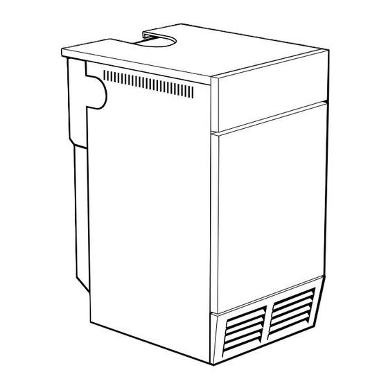
- Page 43 back LIST OF PARTS 80 BOILER CASING ASSEMBLY Legend. 46. Baseplate. 62. Casing complete. 63. Controls panel complete. 71. Controls front panel (door) 73. Side panel - LH 74. Side panel - RH 75. Lower front panel. 76. Top panel. 77.
- Page 44 Gas only. They have been tested and conform with the provisions of BS. 6332 and BS. 5258. Ideal Boilers, P.O. Box 103, National Ave, Kingston upon Hull, HU5 4JN. Telephone: 01482 492 251 Fax: 01482 448 858. Registration No. London 322 137.
Need help?
Do you have a question about the Mexico Super 450 FF and is the answer not in the manual?
Questions and answers