Table of Contents
Advertisement
Quick Links
Download this manual
See also:
Technical Manual
Advertisement
Table of Contents

Related Manuals for Viessmann VITOSOL300


Summary of Contents for Viessmann VITOSOL300
-
Page 1: Installation Instructions
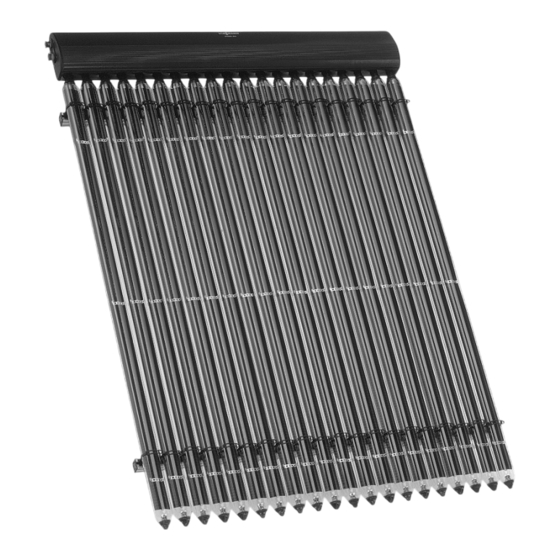
VIESMANN Installation instructions for heating engineers Vitosol 300 Type SP3 Vacuum tube collector based on the heat pipe principle VITOSOL 300 Dispose after installation. 5862 790 GB 5/2005... -
Page 2: Safety Instructions
Safety instructions Please follow these safety instructions closely to prevent accidents and material losses. Safety instructions explained Regulations Danger Observe the following when working This symbol warns against the on this system & risk of injury. all legal instructions regarding the prevention of accidents, &... -
Page 3: Table Of Contents
Index Preparing the installation Earthing and lightning protection of the solar heating system ....... Installation steps Vertical roof top installation ................. & Component summary ................& Fitting roof hooks or mounting brackets ............ & Fitting the mounting rails ................13 &... -
Page 4: Earthing And Lightning Protection Of The Solar Heating System
Earthing and lightning protection of the solar heating system Install an electrical conductor on the The connection of the collector sys- pipework system of the solar circuit in tem to a new or existing lightning pro- the lower part of the building in com- tection system or the provision of pliance with VDE or local regulations. -
Page 5: Vertical Roof Top Installation
Vertical roof top installation Component summary... - Page 6 Vertical roof top installation (cont.) Roof tile cover For all forms of roofing 1 Timber qQ Clamping bracket qW T-slot bolt & 38 x 58 x 2430 mm qE Washer & 30 x 100 x 2430 mm 2 Roof hooks qR Hexagon nut 3 Zinc-plated countersunk chip- qT Mounting rail...
-
Page 7: Fitting Roof Hooks Or Mounting Brackets
Vertical roof top installation (cont.) Fitting roof hooks or mounting brackets Overview — Installation with roof hooks E Roof hooks Dimension x according to the width of F Timber, 38 x 58 mm the tile head. (only for roof tiles) A Vacuum tube G Timber, 30 x 100 mm B Clamping bolt... - Page 8 Vertical roof top installation (cont.) Overview — Installation with mounting brackets (e.g. on sheet steel roofs) A Vacuum tube E Mounting rail B Clamping bolt F Retaining plate C Mounting rail with tube holders G Connecting chamber D Mounting bracket...
- Page 9 Vertical roof top installation (cont.) Secure the mounting brackets to the substructure in accordance with the dimensions given in the illustrations on page 8 and 10.
- Page 10 Vertical roof top installation (cont.) For installations without roof hooks, mounting brackets are used in place of the roof hooks. Centre the mounting rails, maintaining dimension f = 81 mm. Combination mm b mm c (tubes) — — — — —...
- Page 11 Vertical roof top installation (cont.) Fitting roof hooks for roof tile cover 1. Push up the roof tiles in accor- 3. Hook the roof hooks into the timber dance with the dimensions shown in accordance with the dimensions in the illustration on page 7. shown in the illustration on page 10.
- Page 12 Vertical roof top installation (cont.) Fitting roof hooks for slate cover 1. Mark the position of each roof hook in accordance with the dimensions shown in the illustration on page 10. 2. Remove slates from the roof hook areas. 3. Secure the roof hooks to the roof surface.
-
Page 13: Fitting The Mounting Rails
Vertical roof top installation (cont.) Fitting roof hooks for plain tile cover 1. Mark the position of each roof hook in accordance with the dimensions shown in the illustration on page 10. 2. Remove tiles from the roof in the hook areas. - Page 14 Vertical roof top installation (cont.) 1. Secure the mounting rails to the roof hooks or mounting brackets; align vertically and horizontally. A Roof hooks or mounting brackets 2. Align and fix the retaining plates onto the mounting rail.
- Page 15 Vertical roof top installation (cont.) Centre the mounting rails, maintaining dimension f = 81 mm. 3. Fit clamping bolts onto the mount- ing rails; do not yet tighten the bolts. 4. Click the mounting rails with tube holders into the clamping bolts; align and fasten.
-
Page 16: Fitting The Connecting Chamber
Vertical roof top installation (cont.) Fitting the connecting chamber Turn T-slot bolt 90° for all installation steps. 1. Position the connecting chamber 3. Tighten the mounting rails with the onto the mounting rails and click clamping bolts. into the retaining plates. 4. -
Page 17: Installation On Flat Roofs
Installation on flat roofs Component summary... -
Page 18: Determining The Collector Row Distance "Z
Installation on flat roofs (cont.) 1 Rawl plug S 10 Accessories for one collector array 2 Washer wQ Connecting pipe 3 Hexagon screw wW Thermal insulation 4 Fixing leg with screw, washer and Connection set: Connecting pipe (short) 5 Support Connecting pipe (long) 6 Bracing rail Locking ring fitting (elbow 90°),... -
Page 19: Fitting The Support Frame
Installation on flat roofs (cont.) 1. Determine the angle of the sun β. 2. Calculating dimension. z: This should be chosen so that the h = 2020 mm α = 45° midday sun on 21.12. falls on the β = 16.5° second row of collectors without being obstructed by shadows. - Page 20 Installation on flat roofs (cont.) To calculate dimension z, see page 18. A Foot A B Foot B 1. Position feet A and B on a solid foundation, in accordance with the Type SP3 dimensions on page 20. 1200...
- Page 21 Installation on flat roofs (cont.) 2. Secure the mounting brackets onto feet A and B according to the dimensions on page 20.
- Page 22 Installation on flat roofs (cont.) 3. Fix the supports to the front mount- 6. Push the upper part of the supports ing brackets. into the lower part to achieve the desired angle of inclination. 4. Remove the machine screw. 5. Release the locking screw.
- Page 23 Installation on flat roofs (cont.) 7. Tighten the screws. 8. Fix connectors to the rear mounting brackets. Note The machine screw is no longer required if an inclination angle of 35° has been selected. 9. Fix a bracing rail between the sup- ports.
-
Page 24: Fitting The Mounting Rails And Connecting Chamber
Installation on flat roofs (cont.) Fitting the mounting rails and connecting chamber Turn T-slot bolts 90° for all installation steps. A Retaining plate 1. Fix the clamping bolts to the sup- 4. Align the connecting chamber. ports according to the dimensions Note in the illustration on page 20;... -
Page 25: Water Connections
Installation on flat roofs (cont.) 6. Where several collectors are installed side-by-side, continue with "Installing the connecting chamber" on page 25, otherwise continue with "Fitting the connec- tion set" on page 26. Water connections Installing the connecting chamber A Groove for retaining clip... -
Page 26: Fitting The Connection Set
Water connections (cont.) Interconnecting pipes should not 4. Secure interconnecting pipes with show any signs of damage. retaining clips; click clips into the Only lubricate all plug-in connections groove in the interconnecting pipes (O-ring seal) found on the collectors through the holes in the collector with the special lubricating grease connectors. - Page 27 Water connections (cont.) A Nut for the retaining clip VL Flow (short connection pipe) RL Return (long connection pipe) 1. Remove the retaining clips. 5. Thread the locking ring fittings onto the connecting pipe. 2. Push the connecting pipes in as far as possible.
-
Page 28: Fitting The Vacuum Tubes And Collector Temperature Sensor
Water connections (cont.) 7. Check the system pressure and 8. Fit the thermal insulation cap. test for leaks. "Vitosol" service instruc- tions. Fitting the vacuum tubes and collector temperature sensor Danger The vacuum tubes can become hot or break if insufficient care is taken.This can lead to severe burns or injury. - Page 29 Water connections (cont.) A Dual-pipe heat exchanger B Clip C Template...
- Page 30 Water connections (cont.) 1. Remove the rubber seal only out 5. For south-facing roofs, adjust the of the groove of the chamber angle of inclination of the absor- cover and pivot back the cover. ber with the enclosed template. Direct the coated side of the 2.
-
Page 31: Installation
Installation Please note Incorrect installation can lead to collector damage. Use only gunmetal and brass fittings and copper pipes for the installa- tion. Use hemp only in conjunction with pressure and temperature resistant sealants (e.g. Viscotex Solarpaste from Locher, CH-9450 Altstätten). Never step onto solar panels. -
Page 32: Commissioning And Adjustment
Installation (cont.) M Air separator O Solar control unit N DHW cylinder P Air vent valve 1. Route pipes so that they can be 3. The expansion vessel must be completely vented. Install at least approved to DIN 4807 and must be one air vent valve with shut-off installed with a thermal insulating facility at the highest point of the... - Page 36 Viessmann Limited Hortonwood 30, Telford, TF1 7YP, GB Telephone: +44 1952 675000 Fax: +44 1952 675040 www.viessmann.com...
Need help?
Do you have a question about the VITOSOL300 and is the answer not in the manual?
Questions and answers