Table of Contents
Advertisement
Quick Links
Advertisement
Table of Contents

Related Manuals for Dawson Tools DAN120


Summary of Contents for Dawson Tools DAN120
- Page 1 Dawson DAN120 Analog Multimeter User’s Manual...
-
Page 2: Table Of Contents
TABLE OF CONTENTS LIMITED WARRANTY AND LIMITATION OF LIABILITY ............. 3 Out of the Box ..........3 Accessories ..........4 Safety Information ........6 Certification ..........6 INTRODUCTION ........... 7 Overview ............. 7 Figures and Components ......7 USING THE METER ........8 Preparation .......... - Page 3 Fuses Test ..........16 Switches ............ 16 Transistor Gain Measurement (dB) ..17 1.5V and 9V Battery Test ......18 SPECIFICATIONS ........18 General Specification ........ 18 MAINTENANCE AND REPAIR ..... 19 Repair ............19 Replacing Batteries ........20 Replacing Fuses ........20 CONTACT DAWSON ........
-
Page 4: Limited Warranty And Limitation Of Liability
LIMITED WARRANTY AND LIMITATION OF LIABILITY This instrument from Dawson Tools Inc. will be free from defects in workmanship and material for three years from the date of original purchase. This warranty does not cover defects resulting from damage caused by the user such as drops, neglect, misuse, unauthorized alteration, usage outside of specified conditions, contamination, or improper repair/maintenance. -
Page 5: Accessories
Accessories Test Leads 1 pair 1.5V AA Battery Safety Information WARNING TO REDUCE THE RISK OF FIRE, ELECTRICAL SHOCK, PRODUCT DAMAGE OR PERSONAL INJURY, PLEASE FOLLOW THE SAFETY INSTRUCTIONS DESCRIBED IN THE USER MANUAL. READ THE USER MANUALS BEFORE USING THE METER. - Page 6 should be performed only by qualified personnel. Avoid direct exposure to sunlight to ensure extended life of the Meter. Do not place Meter in a strong magnetic field; this may cause false readings. Use only the batteries indicated in the Technical Spec.
-
Page 7: Certification
Important Safety Information Never use the Meter to measure voltages that might exceed 1000V DC/AC above earth ground. Always be careful when working with voltages above 60V DC or 30V AC RMS. Keep fingers behind the probe barriers while measuring. ... -
Page 8: Introduction
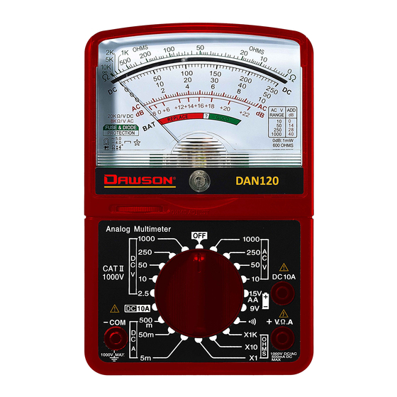
Introduction Overview The DAN120 is a compact analog multimeter featuring large analog scale. Functions include AC/DC voltage, AC/DC current measurement, resistance measurement and battery test. This DAN120 meter is ideal for both professional and hobbyists. Figures and Components Front Panel... -
Page 9: Using The Meter
Using the Meter Preparation Fully plug the test leads into the input jacks. Red lead to “VΩA+” input and black lead to “COM-“ input. Calibration of the scale is needed before making measurement. Use a small size flat tip screwdriver to adjust the black knob located in the center of the Meter, next to the Dawson logo. -
Page 10: Reading The Scale
Reading the Scale General Make sure to align the needle with the scale. Resistance (Ohms - Ω) Use the top scale (Green) to read resistance. If the meter is set to X10, multiply the resistance value by 10, and in x1K multiply the resistance value by 1000. DC Voltage (V DC) Use the middle scale (Black). -
Page 11: Dc/Ac Voltage Measurement
NOTE: For 2.5V range measurement, use the scale of 250V and divide by 100. For 1000V range measurement, use the scale of 10V and multiply by 100. AC Voltage (V AC) Use the same numbers and procedures used for DC voltage measurement. -
Page 12: Common Ac Voltage Measurements
Connect the test leads to the circuit in series, that is, to let the current of the circuit to pass the Meter through test leads. If the needle deflects to the left, reverse the leads connection. Read of the scale as described in Reading the Scale. Common AC Voltage Measurements Wall Receptacles If the receptacle is controlled by a switch, make sure the... -
Page 13: Dc Current Measurement (Ma)
DC Current Measurement (mA) WARNING DO NOT APPLY VOLTAGE TEST WHEN ROTARY SWITCH IS IN CURRENT MODE Plug the test leads in to input jacks. Connect the test lead to the target, red to positive and black to negative terminals. ... - Page 14 It is important to point out that milliamps can also be expressed as thousandths of an Ampere; therefore 500 milliamps is 500 thousandths of one Amp. The 500mA function of your multimeter is commonly used by electronics repair technicians and hobbyists to troubleshoot various low voltage circuits.
-
Page 15: Dc 10A Measurement
DC 10A Measurement WARNING DO NOT APPLY VOLTAGE TEST WHEN ROTARY SWITCH IS IN CURRENT MODE A separate input jack is provided for measurement of DC current up to 10A. Maximum measuring time is 15 seconds with a 30 second interval between tests. Rotate the switch to “10A”... -
Page 16: Extension Cords Continuity Test
Plug the test leads into input jacks. Rotate the switch to “Ohm” mode. Choose the highest range (x1K) when the value to be measured is unknown. Connect the test lead to the target, polarity can be ignored. -
Page 17: Fuses Test
connected to the slot. If none of the tests appear to have 0 ohm resistance, the continuity test fails. Fig.4 Fuses Test Remove the fuse from the appliance. Touch each end of fuse (fig.5) with the test leads and perform the continuity test. -
Page 18: Transistor Gain Measurement (Db)
indictor will move to ~0 ohm. On other switches such as three-way light switches or double pole double throw (ON-OFF-ON) switches, each ON position will need to be tested. Alternate the test leads between the switch terminals to determine which two terminals control the ON position. -
Page 19: 1.5V And 9V Battery Test
NOTE: Circuit impedance must be at least 600 ohms. 0 decibels = 1 milliwatt. 1.5V and 9V Battery Test To check if the battery is in good or bad condition, switch the rotary switch to “1.5V AA” or “9V” on the right side according to the battery type. -
Page 20: Maintenance And Repair
AC voltage = ±5 % full scale of range Resistance = ±4% arc of scale length Operating altitude: max. 2000 meters (7000 ft.) Display: Analog display Fuse: F500mA/250V Φ 5.2x20mm F10A/250V Φ 5.2x20mm Power Supply : 1.5V×1 AA batteries ... -
Page 21: Replacing Batteries
Repair or service not covered in this manual should be performed only by the authorized service center or qualified personnel. Replacing Batteries Follow these steps to replace batteries: Turn off the Meter. Loosen the back cover and remove from case. ... -
Page 22: Contact Dawson
Contact Dawson Dawson Tools, Inc. 1142 S. Diamond Bar Blvd., #858 Diamond Bar, CA 91765 Phone: (310) 728-6220 www.DawsonTools,com Do not recycle...
Need help?
Do you have a question about the DAN120 and is the answer not in the manual?
Questions and answers