
Related Manuals for digico D5 Live


Summary of Contents for digico D5 Live
- Page 1 DIGITAL CONSOLE INTERCONNECTION SYSTEM SETUP & INSTALLATION MANUAL QUICK START GUIDE INCLUDING ISSUE B...
- Page 2 Setup & Installation Manual Page 2...
-
Page 3: Table Of Contents
Digico UK Ltd. Information in this manual is subject to change without notice, and does not represent a commitment on the part of the vendor. Digico UK Ltd shall not be liable for any loss or damage whatsoever arising from the use of information or any error contained in this manual. -
Page 4: Quick Start Guide
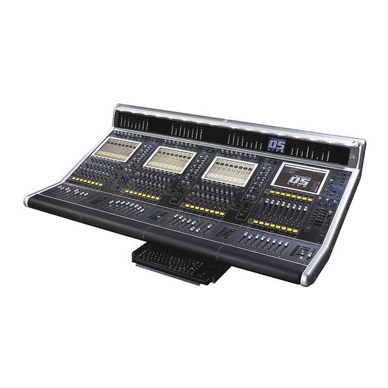
CONNECTING UP The Digico D5 consists of the Mixer, 2 or 3 audio interface racks and various cables. Refer to the connection diagram following. The “Local” Rack has an approximately equal mix of XLR inputs and outputs and few AES/EBU connections on 1 module. This is used adjacent to the mixer for local inputs and outputs such as FX send/returns. - Page 5 Page 5...
-
Page 6: Introduction
D5, in order to help their installation and connection of their new console. Digico hope that this manual answers all the questions which may be asked by system designers and installers, but should there be any issues unresolved for your particular installation, the local distributor or the factory will be pleased to assist. -
Page 7: Rack Notes
All analogue inputs and outputs are balanced and symmetrical, but not floating, because of their transformerless design. Installers should use good earthing practice, as with any large audio installation. Digico can provide copies of AES papers on this subject upon request. - Rack Control Panel Connections .......... - Page 8 Setup & Installation Manual I/O Rack Units Example Installation............... This shows the standard "Stage 1" rack, with 56 Mic inputs and 8 line outputs. Rack Module Connections ............Audio connections to the Rack Modules are made using appropriate connectors for the type of module. See the Connector Tables for a list of the different connectors used in the Rack Modules.
-
Page 9: Synchronisation Connections
Synchronisation Connections ............. When the D5 is used with only analogue siganls connected to both inputs and outputs syncronisation does not need to be considered. In this case the mixer is run from its own internal master or Optocore clock. There are, in fact, two separate synchronisation systems which use different connections - the Sample Word Clock (or Digital Sync) and the Timecode system (not usually used for conventional live sound applications). -
Page 10: Connector Tables
Setup & Installation Manual Connections........Worksurface Rear Panel ............... Function Connector Comments MADI Audio I/O Female BNC 2 or 4 Pairs of I/O Optocore Stratos HMA 2 Bidrectional dual connector RS-422 Machine Control Female D-9 Sony P2 Protocol LTC Time Code In FXLR Balanced, Pin 2 Hot LTC Time Code Out... -
Page 11: Optical Connections
The Optocore® system used in Digico mixers is a high speed digital audio data system that allows multiple interface racks to be connected “daisy chain” along a single optical system. - Page 12 Setup & Installation Manual Care of the optical cable system..............Whilst the system is very robust, like all connector systems it should be treated with care, the show de- pends on it! The Stratos HMA connector is a precision machined device containing 2 lenses and an 1/2 turn bayonet style screw locking device.
-
Page 13: External Displays
Note about LCD Monitors................In Digico’s experience, if a modern LCD monitor (as opposed to conventional CRT based units) is used at a resolution below its specified design figure, this may actually prove not to work correctly. Typical prob- lems are poor vertical edge definition and shimmering of the picture. - Page 14 Setup & Installation Manual The change the resolution requires changes to internal set up files of the embedded control computer and this should only be done by a technician familiar with PC software set-up operations. See setup notes following. Changing Overview screen set-up..........The change the overview screen resolution requires changes to the Windows set-up and the D5 set-up files.
-
Page 15: Miscelaneous Notes
As a result, the product as delivered may vary in small ways from the details in this manual. Any specifica- tion which is critical for a user's application should be confirmed with Digico at the time of ordering. If there... -
Page 16: Hardware Confirgurations
Setup & Installation Manual D5 Standard Hardware Configurations......D5 56 - 64 Processing Channels + 2 x MADI interfaces (2 optical Optocore® System) D5 56E - 96 Processing Channels + 4 x MADI interfaces (2 optical Optocore® System) 1 Stage Rack 56 Mic Inputs 8 Analogue Line Outputs Optical MADI Interface and optical cable drum with 100m... -
Page 17: Index
Index Modem 15 AES/EBU Sync 9 Optical cables 12 Cables, MADI 8 Connector Tables 10 Optical cables 12 Cooling Optocore System 11 I/O Rack 7 Overview screen 14 Worksurface 6 Paint Finishes 15 Digital Sync Connections 9 Display monitors 12 Rack connections Rack setup 11 External display 13... - Page 18 Setup & Installation Manual Page 18...
Need help?
Do you have a question about the D5 Live and is the answer not in the manual?
Questions and answers