Table of Contents
Advertisement
Quick Links
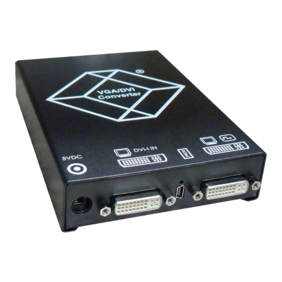
Media/DVI Converters
Convert and output video signals of one or more
video sources (computer, CPU, camera, or DVD
player) in DVI-D format.
Order toll-free in the U.S.: Call 877-877-BBOX (outside U.S. call 724-746-5500)
Customer
FREE technical support 24 hours a day, 7 days a week: Call 724-746-5500 or fax
Support
724-746-0746 • Mailing address: Black Box Corporation, 1000 Park Drive, Lawrence,
Information
PA 15055-1018 • Web site: www.blackbox.com • E-mail: info@blackbox.com
ACS411A-R2
ACS412A
BLACK BOX
ACS413A
ACS414A
®
Advertisement
Table of Contents

Subscribe to Our Youtube Channel
Related Manuals for Black Box ACS411A-R2


Summary of Contents for Black Box ACS411A-R2
- Page 1 Order toll-free in the U.S.: Call 877-877-BBOX (outside U.S. call 724-746-5500) Customer FREE technical support 24 hours a day, 7 days a week: Call 724-746-5500 or fax Support 724-746-0746 • Mailing address: Black Box Corporation, 1000 Park Drive, Lawrence, Information PA 15055-1018 • Web site: www.blackbox.com • E-mail: info@blackbox.com...
- Page 2 Trademarks Used in this Manual Trademarks Used in this Manual Black Box and the Double Diamond logo are registered trademarks of BB Technologies, Inc. IBM is a registered trademark of International Business Machines Corporation. Any other trademarks mentioned in this manual are acknowledged to be the property of the trademark owners.
- Page 3 FCC and IC RFI Statements/NOM Statement FEDERAL COMMUNICATIONS COMMISSION AND INDUSTRY CANADA RADIO FREQUENCY INTERFERENCE STATEMENTS This equipment generates, uses, and can radiate radio-frequency energy, and if not installed and used properly, that is, in strict accordance with the manufacturer’s instructions, may cause inter ference to radio communication. It has been tested and found to comply with the limits for a Class A computing device in accordance with the specifications in Subpart B of Part 15 of FCC rules, which are designed to provide reasonable protection against such interference...
- Page 4 NOM Statement 4. Todas las instrucciones de operación y uso deben ser seguidas. 5. El aparato eléctrico no deberá ser usado cerca del agua—por ejemplo, cerca de la tina de baño, lavabo, sótano mojado o cerca de una alberca, etc. 6.
- Page 5 NOM Statement 16. El cable de corriente deberá ser desconectado del cuando el equipo no sea usado por un largo periodo de tiempo. 17. Cuidado debe ser tomado de tal manera que objectos liquidos no sean derramados sobre la cubierta u orificios de ventilación. 18.
- Page 6 • Do not attempt to open or repair a power supply unit. • Do not attempt to open or repair the DVI Converter. There are no user serviceable parts inside. • Contact Black Box Technical Support at 724-746-5500 or info@blackbox.com if there is a fault. Page 6...
-
Page 7: Table Of Contents
2.1 Introduction ..................22 Available Products ................23 Upgrade Kits ................... 23 What’s Included ................23 Hardware Description ..............26 2.5.1 ACS411A-R2 ..............26 2.5.2 ACS412A ................27 2.5.3 ACS413A ................28 2.5.4 ACS414A ................29 Status LEDs ..................30 Installation .................. - Page 8 Download DDC Using the Infrared Remote Control ...51 5.2.2 Download DDC Using the OSD ..........51 Troubleshooting ..................52 Blank Screen ................... 52 Picture ..................53 General ..................54 Contacting Black Box ..............54 Shipping and Packaging ..............54 Glossary ..................55 Page 8 724-746-5500 | blackbox.com...
-
Page 9: Specifications
Power — ACS411A-R2: 5-VDC external power supply, 900 mA; ACS412A–ACS414A: 5-VDC external power supply, 1100 mA Size — ACS411A-R2: 4"H x 5.6"W x 1.1"D (10.3 x 14.3 x 2.9 cm); ACS412A–ACS414A: 4"H X 5.6"W x 1.7"D (10.3 x 14.3 x 4.3 cm) Weight —... - Page 10 Chapter 1: Specifications Table 1-1. Supported video modes for DVI, VGA, EGA, and RGB. Index Description Hres Vres V-Freq H-Freq Dot Clk CGA (TTL) 59.9 15.7 50.0 15.6 MONA S5 54.4 24.3 14.0 AS 230/235/OS 252 50.0 15.6 10.0 GBE 3977-62x32 50.0 15.6 10.0...
- Page 11 Chapter 1: Specifications Table 1-1 (Continued). Supported video modes for DVI, VGA, EGA, and RGB. Index Description Hres Vres V-Freq H-Freq Dot Clk 70.2 31.5 25.2 84.9 37.8 31.4 IVE 3 50.1 21.8 17.4 IVE 4 50.0 20.0 16.1 Custom 1 49.9 20.6 16.5...
- Page 12 Chapter 1: Specifications Table 1-1 (Continued). Supported video modes for DVI, VGA, EGA, and RGB. Index Description Hres Vres V-Freq H-Freq Dot Clk VESA Standard 72.9 37.9 31.5 VESA Standard 84.9 43.2 35.9 NEC 15 kHz 60.0 15.0 13.5 NEC 15 kHz i 30.0 15.0 13.5...
- Page 13 Chapter 1: Specifications Table 1-1 (Continued). Supported video modes for DVI, VGA, EGA, and RGB. Index Description Hres Vres V-Freq H-Freq Dot Clk 71.9 43.2 42.9 74.9 45.1 45.5 85.0 51.4 51.8 NEC 44 kHz 72.2 44.0 44.0 CP 527/60 60.0 30.9 32.8...
- Page 14 Chapter 1: Specifications Table 1-1 (Continued). Supported video modes for DVI, VGA, EGA, and RGB. Index Description Hres Vres V-Freq H-Freq Dot Clk DMT1185 1152 70.0 63.5 100.1 VESA Standard 1152 70.0 63.8 94.4 VESA Standard 1152 75.0 67.5 108.0 1152 86.1 77.1...
- Page 15 Chapter 1: Specifications Table 1-1 (Continued). Supported video modes for DVI, VGA, EGA, and RGB. Index Description Hres Vres V-Freq H-Freq Dot Clk HP Workstation B123L 1280 1024 72.0 78.1 135.0 VESA Standard 1280 1024 75.0 79.9 134.9 VESA Standard 1280 1024 85.0...
- Page 16 Chapter 1: Specifications Table 1-1 (Continued). Supported video modes for DVI, VGA, EGA, and RGB. Index Description Hres Vres V-Freq H-Freq Dot Clk 1080p 1920 1080 49.7 55.9 147.6 1080p 1920 1080 59.7 66.8 172.1 1080p 1920 1080 60.0 67.5 148.5 WUXGA 1920...
-
Page 17: Connector Pinouts
Chapter 1: Specifications 1.3 Connector Pinouts 1.3.1 DVI-D Single-Link Connector Figure 1-1. Table 1-3. DVI-D Single-Link Connector pinouts. Signal Signal Signal T.M.D.S. data 2- T.M.D.S. data 1- T.M.D.S. data 0- T.M.D.S. data 2+ T.M.D.S. data 1+ T.M.D.S. data 0+ T.M.D.S. data 2 GND T.M.D.S. -
Page 18: Dvi-I Single-Link Connector
Chapter 1: Specifications 1.3.2 DVI-I Single-Link Connector Figure 1-2. Table 1-4. DVI-I Single-Link Connector pinouts. Signal Signal Signal T.M.D.S. data 2- T.M.D.S. data 1- T.M.D.S. data 0- T.M.D.S. data 2+ T.M.D.S. data 1+ T.M.D.S. data 0+ T.M.D.S. data 2 GND T.M.D.S. -
Page 19: Rca (Cinch) Connector
Chapter 1: Specifications 1.3.3 RCA (Cinch) Connector Figure 1-3. RCA (Cinch) connector. Table 1-5. RCA (Cinch) connector pinouts. Signal Data IN/OUT 1.3.4 BNC (SDI, RGB) Connector Figure 1-4. BNC connector. Table 1-6. BNC (SDI, RGB) connector pinouts. Signal Data IN Page 19 724-746-5500 | blackbox.com... -
Page 20: Mini-Din (S-Video) Connector
Chapter 1: Specifications 1.3.5 Mini-DIN (S-Video) Connector Figure 1-5. Mini-DIN (S-Video) connector. Table 1-7. Mini-DIN (S-Video) connector pinouts. Signal GND (Y) GND (C) Luminance (Y) Chrominance (C) 1.3.6 DB9 (EGA) Connector Figure 1-6. DB9 connector. Table 1-8. DB9 (EGA) connector pinouts. Red (LSB) —... -
Page 21: Power Supply Connector
Chapter 1: Specifications 1.3.7 Power Supply Connector Figure 1-7. Table 1-9. Power Supply connector pinouts. Signal Inside VCC (+5 VDC) Outside Page 21 724-746-5500 | blackbox.com... -
Page 22: Overview
Chapter 1: Specifications 2. Overview 2.1 Introduction The DVI Converter is used to convert and output video signals of one or more video sources (computer, CPU, camera, DVD player) in the DVI-D format. Models are available to convert DVI-D single-link, DVI-I single-link, S-Video (Y/C), SDI Video, EGA (DB9), Composite Video (BAS/FBAS), Component Video (YPbPr), RGB Video. -
Page 23: Available Products
Table 2-3. Upgrade kits. Product Code Description ACS1009A-RMK 19" 1U rackmount kit used to mount up to four ACS411A-R2 devices ACS2209A-RMK 19" 1U rackmount kit used to mount up to four ACS412A, ACS413A, or ACS414A devices ACS4001A-DRM Mounting plate used to mount by screws/snap on for ACS411A-R2... - Page 24 • VGA cable (1.8-m, VGA connector to DVI-I connector) Figure 2-2. VGA cable. • Infrared remote control ACS412A contains everything listed under ACS411A-R2, plus the following items: • EGA cable (6-ft. [1.8 -m], [1] DB9 connector) Figure 2-3. EGA cable.
- Page 25 • Component video cable (5-ft. [1.5-m], [3] RCA connectors) Figure 2-7. Component video cable. • S-Video (9.6-ft. [3.0-m], [1] 4-pole mini-DIN connector) Figure 2-8. S-Video cable. ACS414A contains everything listed under ACS411A-R2, plus the following items: • RGB cable (6.4-ft. [2-m], [5] BNC connectors) Figure 2-9. RGB cable.
-
Page 26: Hardware Description
Chapter 2: Overview 2.5 Hardware Description 2.5.1 ACS411A-R2 Rear view Front view Figure 2-10. Front and back views of the ACS411A-R2. Table 2-4. ACS411A-R2 components. Number Component Connect to 5-VDC power supply Input: DVI-I (VGA) Service port IR receiver for remote control... -
Page 27: Acs412A
Chapter 2: Overview 2.5.2 ACS412A Rear view Front view Figure 2-11. Front and back views of the ACS412A. Table 2-5. ACS412A components. Number Component Connect to 5-VDC power supply Input: DVI-I (VGA) Service port IR receiver for remote control Output: DVI-D Input: S-Video (Y/C) Input: FBAS 1 or YPbPr (Pr) Input: FBAS 2 or YPbPr (Y) -
Page 28: Acs413A
Chapter 2: Overview 2.5.3 ACS413A Rear view Front view Figure 2-12. Front and back views of the ACS413A. Table 2-6. ACS413A components. Number Component Connect to 5-VDC power supply Input: DVI-I (VGA) Service port IR receiver for remote control Output: DVI-D Input: S-Video (Y/C) Input: FBAS 1 or YPbPr (Pr) Input: FBAS 2 or YPbPr (Y) -
Page 29: Acs414A
Chapter 2: Overview 2.5.4 ACS414A Rear view Front view Figure 2-13. Front and back views of the ACS414A. Table 2-7. ACS414A components. Number Component Connect to 5-VDC power supply Input: DVI-I (VGA) Service port IR receiver for remote control Output: DVI-D Input: RGB (red) Input: RGB (green) Input: RGB (blue) -
Page 30: Status Leds
The Media Converter has a multi-color LED that indicates the connection status. ACS411A-R2 ACS412A, ACS413A, ACS414A Figure 2-14. Front views showing LEDs on the ACS411A-R2 and ACS412A–ACS414A. Table 2-8. LED 1: Connection and video status. LED Color Description for the Input... -
Page 31: Installation
Chapter 3: Installation 3. Installation 3.1 System Setup NOTE: If you are a first-time user, we recommend that you set up the system with the CPU unit and the CON unit in the same room as a test setup. This will enable you to identify and solve any cabling problems, and experiment with your system more conveniently. - Page 32 Chapter 3: Installation Table 3-1. Example application 1 description (Composite video). Number Component Source (observation camera) Media-/DVI-Converter Monitor Figure 3-2. Example application 2, video input: S-Video. Table 3-2. Example application 2 description (S-Video). Number Component Source (DVD player) Media-/DVI-Converter Monitor Page 32 724-746-5500 | blackbox.com...
-
Page 33: Configuration
Chapter 4: Configuration 4. Configuration 4.1 Infrared Remote Control You can convert the Media-/DVI-Converter via an on-screen display (OSD) and via an infrared remote control. Navigate through the OSD menu items. Figure 4-1. Infrared remote control. NOTE: In the OSD, only the navigation keys of the infrared remote control function. - Page 34 Chapter 4: Configuration Table 4-1 (Continued). Infrared (IR) remote control key functions. Button Description Leave current menu and open upper menu level. Navigate inside the OSD. Select parameters with cursor keys Read and use DDC of the connected monitor. Adjust picture contrast/brightness. Reset the Media/DVI Converter to factory default.
- Page 35 Chapter 4: Configuration Table 4-1 (Continued). Infrared (IR) remote control key functions. Button Description If more than one converter is used, select a single device for OSD access. If more than one converter is used, select all devices for OSD access. Select input signal: VGA, DVI, or SDI.
- Page 36 Chapter 4: Configuration Table 4-1 (Continued). Infrared (IR) remote control key functions. Button Description Select input signal FBAS 1–3 (Cinch) or FBAS 4 (BNC). Page 36 724-746-5500 | blackbox.com...
-
Page 37: On-Screen Display (Osd)
Chapter 4: Configuration 4.2 On-Screen Display (OSD) You can adjust all settings of the Media-/DVI-Converter via the on-screen display (OSD). Figure 4-2. General Structure of the OSD. The left column shows the range of the main menu, the right column shows the current submenus with the respective configuration options. -
Page 38: Main Menu Item "Color Settings
Chapter 4: Configuration 4.2.1 Main Menu Item “Color Settings” This menu offers color-specific settings and configurations for the Media-/DVI- Converter. Figure 4-3. Color Settings screen. Table 4-2. Color Settings screen functions. Menu Item Description Brightness Adjust brightness of the picture. Contrast Adjust contrast of the picture. - Page 39 Chapter 4: Configuration Submenu “Color” This submenu offers advanced color settings for the picture (VGA/RGB/EGA input only). Figure 4-4. Color Settings submenu screen. Table 4-3. Color Settings submenu screen functions. Menu Item Description Auto Color Adjust color values automatically. Color Temperature Adjust color temperature of the picture.
-
Page 40: Main Menu Item "Picture Settings
Chapter 4: Configuration 4.2.2 Main Menu Item “Picture Settings” This menu offers specific picture settings at the Media-/DVI-Converter. Figure 4-5. Picture Settings screen. Table 4-4. Picture Settings screen functions. Menu Item Description Auto Configuration Configure picture settings automatically (VGA/RGB/EGA input only). Adjust pixel phase (that is, the best position for the analog/digital/ Phase conversion within one pixel [VGA/RGB/EGA input only]). - Page 41 Chapter 4: Configuration Table 4-4 (Continued). Picture settings screen functions. Menu Item Description Adjust pixel clock. The pixel clock shows the maximum number of the pixels that are can be displayed horizontally. Even non-visible and inactive pixels are included (VGA/RGB/EGA input only). Clock Example of a wrong pixel clock.
- Page 42 Chapter 4: Configuration “Display Control” Submenu This submenu offers control options for the display of the picture. Figure 4-6. Display Control submenu. Table 4-5. Display Control submenu screen functions. Menu Item Description Select display optiion: • Auto: Scale picture automatically to the maximum value. Display Image •...
-
Page 43: Main Menu Item "Input Settings
Chapter 4: Configuration 4.2.3 Main Menu Item “Input Settings” This menu offers specific settings for the input of the Media-/DVI-Converter. Figure 4-7. Input Settings screen. Table 4-6. Input Settings screen functions. Menu Item Description Input Select Select input signal • For FBAS input signal: Select Composite channel. Channel •... -
Page 44: Main Menu Item "Output Settings
Chapter 4: Configuration 4.2.4 Main Menu Item “Output Settings” This menu offers specific settings for the output of the Media-/DVI-Converter. Figure 4-8. Output Settings screen. Table 4-7. Output Settings screen functions. Menu Item Description Select output resolution: • DDC: Use preferred resolution of the monitor’s DDC at the output. Output •... -
Page 45: Main Menu Item "General Settings
Chapter 4: Configuration 4.2.5 Main Menu Item “General Settings” This menu offers general settings for the media converter. Figure 4-9. General Settings screen. Table 4-8. General Settings screen functions. Menu Item Description Open DDC submenu (see the next page). Open Miscellaneous submenu (see the Miscellaneous submenu. It’s described after Miscellaneous the DDC submenu in this manual). - Page 46 Chapter 4: Configuration DDC Submenu This submenu offers DDC specific settings. DDC information is relevant for the output settings and for the connection to a computer or CPU. Figure 4-10. DDC submenu. Table 4-9. DDC submenu options. Menu Item Description Read DDC Use the monitor DDC as the device DDC and save it as DVI or VGA DDC.
- Page 47 Chapter 4: Configuration Miscellaneous Submenu This submenu offers various device specific settings. Figure 4-11. Miscellaneous submenu screen. Table 4-10. Miscellaneous submenu options. Menu Item Description Activate or deactivate the automatic configuration of the picture settings after Auto Adjust changing the video mode. Refresh Rate Change refresh rate if the output is set to DDC.
- Page 48 Chapter 4: Configuration OSD Configuration Submenu This submenu offers various settings for the OSD display. Figure 4-12. OSD Configuration menu. Table 4-11. OSD Configuration submenu options. Menu Item Description OSD Timer Activate and select the time of inactivity after which OSD is closed automatically. OSD Position Adjust vertical and horizontal OSD position on screen.
-
Page 49: Operation
3. Optimize the picture settings for your input signal (see Section 5.1.3). NOTE: If you have problems optimizing picture settings, contact Black Box Technical Support at 724-746-5500 or info@blackbox.com. 5.1.1 Optimization of Output Settings 1. -
Page 50: Picture Settings
Chapter 5: Operation 1. Open the OSD with the infrared remote control. 2. Select “Input Settings” in the main menu (see Section 4.2.3). 3. Test the recommended resolutions that are listed in the menu item “Select Resolution.” The menu item is inactive if there is only one recommended resolution. -
Page 51: Download Ddc Using The Infrared Remote Control
Chapter 5: Operation There are two options to load the DDC information of the connected monitor: • Using the infrared remote control (see Section 5.2.1). • Using the “Read DDC” command in the OSD (see Section 5.2.2). 5.2.1 Download DDC Using Infrared Remote Control 1. -
Page 52: Troubleshooting
Solution #1: Check the connection, length, and quality of the DVI-D cable to monitor; tighten cable thumbscrews. Possible Cause #2: Resolution on the device side is not supported. Solution #2: Contact Black Box Technical Support at 724-746-5500 or info@blackbox.com; we will make a customer specific video mode. Problem: Status LED is violet. -
Page 53: Picture
Chapter 6: Troubleshooting 6.2 Picture Problem: Incorrect picture display. Possible Cause #1: Connection is disturbed. Possible Solution #1: Check the connection, length, and quality of the DVI-D cable to monitor; tighten cable thumbscrews. Possible Cause #2: Transmission parameters are not suitable or not optimally set for conditions. -
Page 54: General
• Package it carefully. We recommend that you use the original container. • If you are returning the unit, make sure you include everything you received with it. Before you ship for return or repair, contact Black Box to get a Return Authorization (RA) number. -
Page 55: Glossary
Chapter 7: Glossary 7. Glossary CATx — Any CAT5e, CAT6, or CAT7 cable. CGA — The Color Graphics Adapter (CGA) is an old analog graphic standard with up to 16 displayable colors and a maximum resolution of 640 x 400 pixels. Component Video —... - Page 56 Chapter 7: Glossary FBAS — The analog color video baseband signal (FBAS) is also called Composite Video and is part of the PAL TV standard. KVM — Keyboard, video, and mouse. Mini-XLR — Industrial standard for electrical plug connections (3-pole) for the transmission of digital audio and control signals.
- Page 57 NOTES Page 57 724-746-5500 | blackbox.com...
- Page 58 NOTES Page 58 724-746-5500 | blackbox.com...
- Page 59 NOTES Page 59 724-746-5500 | blackbox.com...
- Page 60 724-746-5500 or blackbox.com. About Black Box Black Box provides an extensive range of networking and infrastructure products. You’ll find everything from cabinets and racks and power and surge protection products to media converters and Ethernet switches all supported by free, live 24/7 Tech support available in 30 seconds or less.
Need help?
Do you have a question about the ACS411A-R2 and is the answer not in the manual?
Questions and answers