Table of Contents
Advertisement
Quick Links
Advertisement
Table of Contents

Related Manuals for AEG X91384MIO


Summary of Contents for AEG X91384MIO
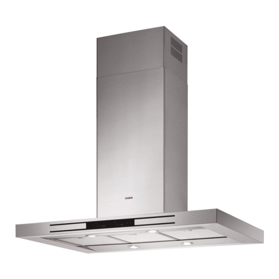
- Page 1 X91384MIO UK EN COOKER HOOD USER MANUAL...
- Page 2 ACCESSORIES AND CONSUMABLES In the AEG webshop, you’ll find everything you need to keep all your AEG appliances looking spotless and working per- fectly. Along with a wide range of accessories designed and...
-
Page 3: Table Of Contents
Contents CONTENTS Important safety information Your appliance Operating instructions Maintenance and cleaning Installation instructions - electrical connections... -
Page 4: For The Installer
To enable you to use your appliance effectively and safely, please read this instruction book carefully before using the appliance and retain for future reference. If you require guidance in the use of the appliance or require further information on AEG Products, please contact our Customer Services Department. -
Page 5: Important Safety Information
IMPORTANT SAFETY INFORMATION IMPORTANT SAFETY INFORMATION These warnings are provided in the interests of your safety. Ensure that you understand them all before installing or using this appliance. Your safety is of paramount importance. If you are unsure about any of the meanings of these warnings contact the Customer Services Department. -
Page 6: Your Appliance
YOUR APPLIANCE YOUR APPLIANCE ���� ���� ����� �����... -
Page 7: Operating Instructions
OPERATING INSTRUCTIONS OPERATING INSTRUCTIONS Button Function Specifications Hood Functions On/Off When the button is touched with the hood turned off, all functions light up (intensity 50%) and are enabled. When the button is touched with the hood in operation, all functions are turned off and disabled (Motor Off + Lights Off). - Page 8 OPERATING INSTRUCTIONS HOOD OPTIONS IN SENSOR MODE When operating in Sensor mode, the type of hob being used has an influence. Two options are available: • Electric hob ; • Gas hob Initially it is set to electric hob. To change the setting, proceed as follows: • Turn the hood off using the hood on/off button...
-
Page 9: Recirculation Mode
OPERATING INSTRUCTIONS OPERATING INSTRUCTIONS This cooker hood can be used to recirculate or extract contamina- ted air. Recirculation Mode The cooker hood is supplied specified for use in the recirculation mode with the charcoal filter fitted. The contaminated air is cleaned by passing through the filters and than back into the kitchen. -
Page 10: Maintenance And Cleaning
MAINTENANCE AND CLEANING MAINTENANCE AND CLEANING Before carrying out any maintenance or leaning isolate the cooker hood from the mains supply. The cooker hood must be kept clean, as a build up of grease or fat can be a fire hazard. External Cleaning The metal casing, grille and chimney should be cleaned at least once a month to keep it looking like new. -
Page 11: Charcoal Filters
MAINTENANCE AND CLEANING MAINTENANCE AND CLEANING Alarm signal reset • Turn the Lights and the Suction Motor off. • Touch button F. The operation is confirmed when the Led goes out. Before carrying out any maintenance or cleaning isolate the cooker hood from the mains supply. Charcoal Filters In the recirculation mode the charcoal filters absorb smells and unwanted odours. - Page 12 MAINTENANCE AND CLEANING MAINTENANCE AND CLEANING Changing the Lighting Warning: This appliance is fitted with a white LED lamp classed as 1M according to EN 60825-1: 1994 + A1:2002 + A2:2001 standards; maximum optical power emitted @439nm: 7µW. Do not look directly at the light through optical devices (binoculars, magnifying glasses…).
-
Page 13: Service And Spare Parts
SERVICE AND SPARE PARTS If you require an engineer or wish to purchase spare parts con- For general enquires concerning your AEG appliance or for fur- tact your local Service Force Centre by telephoning: ther information on AEG products, please contact our Customer Services Department at the address below or visit our website at www.aeg.co.uk... -
Page 14: Standard Guarantee Conditions
Standard Guarantee Conditions We, AEG, undertake that if within 12 months of the date of the purchase this AEG built-in appliance or any part thereof is proved to be defective by reason only of faulty workmanship or materials, the company will, at our option, repair or replace the same FREE OF ANY CHARGE for labour, materials and carriage on condition that: • The appliance has been correctly installed and used only on the electrical supply stated on the rating plate. -
Page 15: Installation Instructions - Electrical Connections
INSTALLATION INSTRUCTIONS - ELECTRICAL CONNECTIONS INSTALLATION INSTRUCTIONS It is dangerous to alter the specifications or attempt to modify this product in any way. Technical Information DIMENSIONS HEIGHT (CANOPY): 60 mm HEIGHT (CHIMNEY): 695 - 415 mm WIDTH (CANOPY): 998 mm WIDTH (CHIMNEY): 350 mm GROSS:... -
Page 16: Installation Requirements
INSTALLING THE COOKER HOOD INSTALLING THE COOKER HOOD Unpacking Please ensure that when the appliance is installed it is ea- sily accessible to an engineer in the event of a breakdown. Before unpacking the cooker hood position the carton with the All installations must comply with the local authorities arrows pointing upwards as illustrated on the carton. - Page 17 INSTALLATION INSTRUCTIONS INSTALLATION INSTRUCTIONS Drilling the Ceiling/shelf and fixing the frame • Use a plumb line to mark the centre of the hob on the ceiling/ support shelf. • Place the drilling template 21 provided on the ceiling/support shelf, making sure that the template is in the correct position by lining up the axes of the template with those of the hob. • Mark the centres of the holes in the template.
-
Page 18: Fixing The Frame
INSTALLATION INSTRUCTIONS INSTALLATION INSTRUCTIONS Fixing The Frame • Loosen the two screws fastening the lower chimney and remove this from the lower frame. • Loosen the two screws fastening the upper chimney and remove this from the upper frame. If you wish to adjust the height of the frame, proceed as follows: • Unfasten the metric screws joining the two columns, located at the sides of the frame. -
Page 19: Electrical Connection And Working Test
�� INSTALLATION INSTRUCTIONS ��� INSTALLATION INSTRUCTIONS �� Connection control group • Unscrew the screws near the Air outlet and use these for attaching the Control Group 50. • Connect up all the connectors to the sockets provided on the Control Board Unit, making sure they are compatible. ��� Flue assembly - mounting the hood body • Position the upper chimney section and fix the upper part to the frame using the 2 screws 12c (2,9 x 6,5) provided. - Page 20 436005218_01 - 101125...
Need help?
Do you have a question about the X91384MIO and is the answer not in the manual?
Questions and answers