Table of Contents
Advertisement
Advertisement
Table of Contents

Related Manuals for Bpt AGATAKIT C 200 UK


Summary of Contents for Bpt AGATAKIT C 200 UK
- Page 1 Installation Manual AGATAKIT C 200 UK 24806770/07-05-2013...
- Page 2 AGK200C03UK HPC/1 AG2K200C03UK AGATA P1 HPC/2 AG3K200C03UK HA/200 HPC/3 A/200R AGK200C03HNA HPC/1+HNA...
-
Page 3: Installation
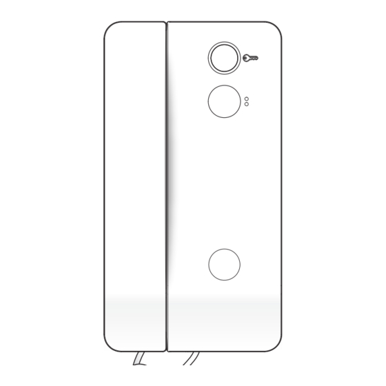
Agata P1 AGATA P1 INSTALLATION Open the device by pressing on the lever at the bottom (fig. 1). Separate the shell from the bottom of the device. Secure the bottom of the device to the wall box using the screws provided (fig. 2 and 3). The box must be installed at an appropriate height for the user. -
Page 4: Operating Characteristics
A/200n A/200N INSTALLATION • The power supplier must ALWAYS be installed horizontally. • The device can be installed on a DIN rail (EN 50022) in an appropriate electric panel or it may be wall-mounted using the protective terminal covers. 43,5 •... - Page 5 Targha 200 TARGHA 200 ACCESSORIES Embedding box Surface housing Chassis Hole plugs Cable guide joints Cable guide joint Spacer Joint Screws Screws and anchors Button Buttons Micro-contact Micro-contacts Button spring Buttons spring Plate Micro-contacts with common call Lighting module Cable-clamp plates Hole plug...
-
Page 6: Recessed Installation
Targha 200 RECESSED INSTALLATION The embedding box HTS must be fitted flush with the wall at an appropriate height. Fit the spacer into embedding boxes to avoid deformation (fig. 1). ATTENTION. To remove the microphone from its seat, pry it off its base using a small screwdriver (figure 2) taking care not to damage the cabling. -
Page 7: Side-By-Side Recessed Installation
Targha 200 ASSEMBLY OF THE BUTTON Push the front plate from the front to release the hole plug (fig. 1) and subsequently remove it. Insert the but- ton as illustrated in fig. 2 and 3. Apply the spring to the button (fig. -
Page 8: Terminal Function
Targha 200 TERMINAL FUNCTION Adjustments TERMINAL BOARDS 12 VDC – Loudspeaker audio 21 + Supply voltage 8 Common call (for witness note) Microphone audio 11 Audio to receiver 12 Audio from receiver TECHNICAL FEATURES 14 Enabling Power supply 12 VDC NOTE. - Page 9 Targha 200 PROGRAMMING Entering and exiting programming To enter programming mode, press keys 1 and 3 at 12345 the same time and then enter the PROGRAMMING CODE (green LED C flashes) Enter the FUNCTION CODE to select the type of fun- ction Once entered the required data, it is possible select another type of function, exit any function selected...
- Page 12 The equipment must be disposed of in compliance with the regulations in force, recycling its component parts wherever possible. Components that qualify as recyclable waste feature the relevant symbol and the material’s abbreviation. BPT S.p.A. a Socio Unico Via Cornia, 1 33079 Sesto al Reghena-PN-Italy www.bpt.it-info@bpt.it...
Need help?
Do you have a question about the AGATAKIT C 200 UK and is the answer not in the manual?
Questions and answers