Table of Contents
Advertisement
Before using your 4PX-2.4GHz system, read this manual carefully in order to use your
IN NORTH AMERICA
Please feel free to contact the Futaba Service Center for assistance in operation, use and
programming. Please be sure to regularly visit the 4PX Frequently Asked Questions web
site at www.futaba-rc.com/faq/. This page includes extensive programming, use, set up and
safety information on the 4PX radio system and is updated regularly. Any technical updates
and US manual corrections will be available on this web page. If you do not find the an-
swers to your questions there, please see the end of our F.A.Q. area for information on con-
tacting us via email for the most rapid and convenient response.
Don't have Internet access? Internet access is available at no charge at most public libraries,
schools, and other public resources. We find internet support to be a fabulous reference for
many modelers as items can be printed and saved for future reference, and can be accessed
at any hour of the day, night, weekend or holiday. If you do not wish to access the internet
for information, however, don't worry. Our support teams are available Monday through
Friday 8-5 Central time to assist you.
FOR SERVICE ONLY:
Futaba Service Center
3002 N. Apollo Drive, Suite 1
Champaign, IL 61822
Phone: 217-398-0007
www.futaba-rc.com/service.html
Email: futabaservice@hobbico.com
OUTSIDE NORTH AMERICA
Please contact your Futaba importer in your region of the world to assist you with any ques-
tions, problems or service needs.
Please recognize that all information in this manual, and all support availability, is based
upon the systems sold in North America only. Products purchased elsewhere may vary. Al-
ways contact your region's support center for assistance.
2
Thank you for purchasing a Futaba 4PX-2.4GHz system.
After reading this manual, store it in a safe place.
R/C set safely.
FOR SUPPORT :
(PROGRAMMING AND USER QUESTIONS)
Please start here for answers to most questions:
www.futaba-rc.com/faq/
Fax: 217-398-7721
Phone: 217-398-8970 option 2
E-mail: support@futaba-rc.com
Advertisement
Table of Contents

Related Manuals for FUTABA 4PX


Summary of Contents for FUTABA 4PX
- Page 1 E-mail: support@futaba-rc.com OUTSIDE NORTH AMERICA Please contact your Futaba importer in your region of the world to assist you with any ques- tions, problems or service needs. Please recognize that all information in this manual, and all support availability, is based upon the systems sold in North America only.
- Page 2 • No part of this manual may be reproduced in any form without prior permission. • The contents of this manual are subject to change without prior notice. • This manual has been carefully written. Please write to Futaba if you feel that any corrections or clarifications should be made.
-
Page 3: Table Of Contents
Table Of Contents For Your Safety As Well As That Of Others .......8 Explanation of Symbols ..............8 2.4GHz System Precautions ............8 High Speed Mode Precautions .............8 Operation Precautions ..............9 Battery Handling Precautions ............10 Storage and Disposal Precautions ..........11 Other Precautions ...............11 Before Using ..............12 Features ..................12 Set Contents ................14... - Page 4 Initial Set-Up ...............36 Preparations (Transmitter) ............36 RF Output & Rx Type Check ............36 Receiver Type Change & How To Link ........37 For Your Safe- Receivers Other Than T-FHSS ..........39 Servo Type Check ..............39 Trigger Ratio Check ..............40 As Well As Trims Initial Set-Up ..............40 Function Map ..............42 Before...
- Page 5 Model memory name set/modify Model Copy ................114 Model memory copy Data Reset ..................116 Model memory reset MC Link Function (ESC Link) ...........117 Special function, Futaba ESC (MC960CR, MC851C, MC602C, MC402CR...etc.) S.BUS Servo ................117 Special function, Futaba S.BUS/S.BUS2 servo parameter setup...
- Page 6 Telemetry System ..............130 Telemetry Menu ..............131 Telemetry :Receiver Battery ...........132 Telemetry :The Drive Battery ..........133 For Your Safe- Telemetry :RPM ..............134 Telemetry :Temperature ............135 As Well As Sensor Menu ................136 Sensor List ................136 Sensor Reload ...............137 Sensor Register ..............138 Before Change Slot ................139 Using Condition Function ..............140...
-
Page 7: For Your Safety As Well As That Of Others
Under other conditions, the set will not operate, or the specified performance will not be displayed even if it operates. In addition, it may cause servo trouble. Futaba will not be responsible for damage, etc. caused by combination with the prod- ucts of other companies. -
Page 8: Operation Precautions
Operation Precautions Warning Do not operate outdoors on rainy days, run through puddles of water or use when visibility is lim- ited. Should any type of moisture (water or snow) enter any component of the system, erratic operation and loss of control may oc- cur. -
Page 9: Battery Handling Precautions
If the power is cut off while run- ning (cruising), a collision may occur. The use of Futaba a genuine NiMH or LiFe battery pack is strongly recommended. -
Page 10: Storage And Disposal Precautions
Always use only genuine Futaba transmitters, receivers, servos, ESCs (electronic speed con- trols), Ni-MH/Ni-Cd/Li-ion batteries and other optional accessories. Futaba will not be responsible for problems caused by the use of other than Futaba genuine parts. Use the parts speci- fied in the instruction manual and catalog. -
Page 11: Before Using
ESC at the front and rear are controlled independently. -Gyro mixing The sensitivity of Futaba car rate gyros can be adjusted from the T4PX. -CPS mixing LED lighting and flashing control using our CPS-1 channel power switch can be matched to steering and throttle operation by switch only. - Page 12 The race time and audible alarm can be set. The 4PX also has a navigation timer effective during practice runs. The target lap and re-/fuel- ing time are indicated by an audible alarm. An up timer and down timer are also provided.
-
Page 13: Set Contents
Always use only genuine Futaba transmitters, receivers, servos, ESCs (electronic speed controls), Ni-MH/Ni-Cd/Li-ion batteries and other optional accessories. Futaba will not be responsible for problems caused by the use of other than Futaba genuine parts. Use the parts specified in the instruction manual and catalog. -
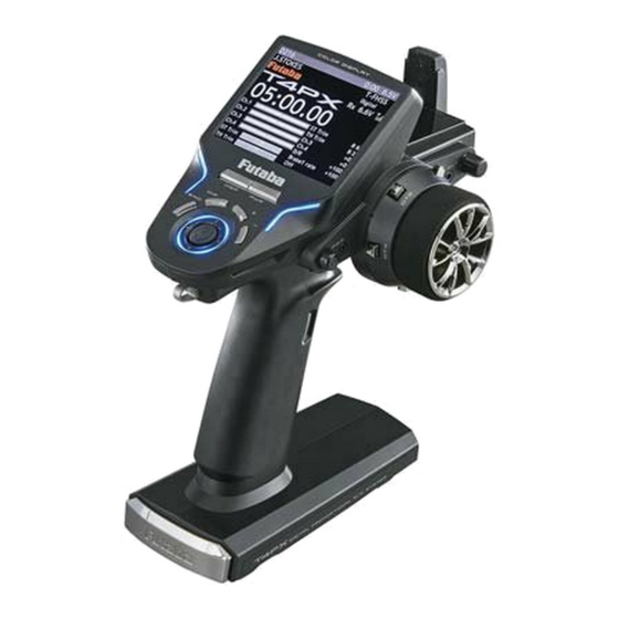
Page 14: Transmitter T4Px
Transmitter T4PX Nomenclature *The switches, dial, and trimmers in the figure are shown in the initial setting position. Digital Trim 2 (DT2) LCD screen (default throttle trim) Digital Trim1 (DT1) (default steering trim) Digital Dial (DL1) Steering wheel Power&Display switch Edit buttons Digital Trim4 (DT4) Push switch 2 (PS2) -
Page 15: Power & Display Switch
Power & Display Switch The power switch and display switch are push switches. When the power switch (PWR) is held down, operation starts by transmitting radio waves. When the display switch is held down, the transmitter side data can be checked and set. When the power is turned off, if the power switch or display switch is held down, the power is turned off. -
Page 16: Digital Trim Operation (Wheel)
Digital Trim Operation (Wheel) (Initial settings: DT1: Steering trim, DT2: Throttle trim, DT3: Channel 3, DT4: Channel 4) Operate digital trim by tilting each trim lever up and down or left and right. The current trim po- sition is displayed on the LCD screen. However, operation is impossible when trim/dial lock (P21) is set. -
Page 17: Mechanical Atl Adjustment
Mechanical ATL Adjustment Make this adjustment when you want to decrease the stroke of the brake (back) side of the throttle trigger for operation feel. Adjustment Using a 1.5mm hex wrench, adjust the trigger brake (reverse) stroke. (The screw moves the throttle trigger stopper.) •... -
Page 18: Trigger Slide Adjustment & Remove The High Point Spring
There is the danger of collision if the power is cut while running (cruising). The use of Futaba genuine NiMH or LiFe batteries is strongly recom-... -
Page 19: When Using The Optional Battery
When Using The Optional Battery When using an optional rechargeable battery, replace the battery as described below. -Always use the optional HT5F1800B, FT2F1700BV2, FT2100BV2 rechargeable battery. -The type of power source used must be set by system setting (p.148). -When the transmitter will not be used for a long time, remove the battery. Battery Replacement Method Caution Refer to the previous description and remove... -
Page 20: Display When Power Switch Turned On
Caution When the charger is not in use, disconnect it from the AC outlet. Do this to prevent accidents and to avoid overheating. If the power is turned on during charging, an RF error will be displayed and an audible alarm will sound. -
Page 21: Changing Wheel Position And Modifying For Left-Hand Use
Changing Wheel Position And Modifying For Left-hand Use Changing the wheel position Modifying for left-hand use The wheel position can be offset by using the The wheel section left and right installa- accessory APA wheel position offset adapter. tion direction can be reversed. (See page 23 for the modification method.) (See page 25 for the modification method.) Angle can be adjusted... - Page 22 Installing the accessory APA steering wheel offset adapter • Obtain 2.5mm hex wrenchs./ Remove the battery. • The length of the screws used at each part differs. When reassembling the steering wheel unit, always use the specified screws. Remove the 2 steering wheel unit mounting screws.
- Page 23 Pass the wiring from the transmitter and the charge unit wiring through the hole in the APA as shown in the figure and insert the 3 connectors at their original positions on the wheel unit PC board. Adapter APA Using a Phillips screwdriver fasten the wheel unit and APA at the desired angle using the 2.5x19 tapping screws in the accessory bag.
- Page 24 Install the assembled steering unit to the transmitter body. Install slowly so that the wiring is not pinched. Installation is easy if inserted in A B order. Install the assembled steering wheel unit and APA to the transmitter using the screw (3.0x12mm cap screw) supplied.
- Page 25 Using a 2.5mm hex wrench, remove the mounting screws (3.0x1.2mm cap) of the opposite side charge unit. Remove the 2 mounting screws completely from the transmitter body. Being careful that the wiring is not too tight slowly remove the charge unit. Remove the connector from the PC board.
- Page 26 Insert the 8WIRE wiring connector onto the charge unit connector, and install the charge unit and transmitter body with the mounting screws. Charge unit mounting screws Install the PS5 switch cap and mounting plate removed at step 1 at the opposite side of the transmitter body.
-
Page 27: Using The Optional Angle Spacer
Using the optional angle spacer The wheel mounting angle can be changed by using the optional angle spacer. Three 2.5x10mm tapping screws are supplied with the angle spacer. When using and not using the APA, refer to the following installation. Obtain a Phillips screwdriver. -
Page 28: Non-Telemetry Led (Telemetry Off Sign)
Non-telemetry LED (telemetry OFF sign) When the telemetry function is inhibited by race regulations, a special LED lights when the telemetry function is OFF to confirm that the telemetry function is not operating. Non-telemetry LED (Lit when telemetry function is OFF) Handling the antenna and card slot and receiver About T4PX Antenna Cannot rotate more than... -
Page 29: Handling An Microsd Card (Commercial Product)
-When a microSD card is installed in the T4PX transmitter, a folder called "Futaba" is cre- ated. Folders called "LOG" and "MODEL" are created in this folder. The "MODEL" folder stores the model data and the "LOG"... -
Page 30: Receiver Terminology
Under other conditions, the set will not operate, or the specified performance will not be displayed even if it operates. In addition, it may cause trouble with servos and other equipment. Futaba will not be responsible for damage, etc. caused by combination with the products of other companies. -
Page 31: Installation
Installation Receiver And Servo Connections Connect the receiver and servos as shown below. Connect and install the receiver and ser- vos in accordance with "Installation Safety Precautions" on the next page. The figure shown below is an example. The method of connecting the motor controller to the motor and battery depends on the motor controller used. -
Page 32: Installation Safety Precautions
Installation Safety Precautions Warning Receiver (receiver antenna) Do not cut or bundle the receiver antenna wire. Do not bundle the receiver antenna wire together with the motor controller lead wire. Keep the receiver antenna wire at least 1cm away from motor, battery, and other wiring carrying heavy current. Do not use a metal receiver antenna holder on a plate made of metal, carbon, or other conductive material. - Page 33 Warning Connector Connections Be sure the receiver, servo, battery and connectors are fully and firmly connected. If vibration from the model causes a connector to work loose while the model is in operation, you may lose control . Servo Installation When you install the servos, always use the rubber grommets provided in servo hardware bags.
- Page 34 Warning Electronic Speed Cont Install the heat sinks where they will not come in contact with aluminum, carbon fiber or other parts that conduct electricity. If the FET Amp (Electronic speed control) heat sinks touch other materials that conduct electricity a short circuit could oc- cur.
-
Page 35: Initial Set-Up
*When the "PWR" side power switch is set to ON and radio waves are output normally, "T-FHSS", "S-FHSS", or "FASST" is displayed. If not displayed, there is probably an abnormality or trouble so contact a Futaba Service Center. When a screen is displayed at the "DSP" side, "Display" is dis- played. -
Page 36: Receiver Type Change & How To Link
Receiver Type Change & How To Link First set up the receiver. Setting changes are immediately reflected. Next, the transmitter and receiver are linked and the receiver memorizes the transmitter ID number so that sig- nals from other transmitters will not be received. In addition, with the T-FHSS telemetry system, the transmitter simultaneously memorizes the receiver ID numbers so that data from other re-... - Page 37 Bring the transmitter and receiver within 50cm of each other (antennas do not touch) and turn on the receiver power. Move the cursor to "Link" by T4PX transmitter (JOG) button up or down operation. When the (JOG) button is pressed, a chime will sound and the T4PX will enter the link mode for 20 seconds.
-
Page 38: Receivers Other Than T-Fhss
Precaution: If there are many Futaba 2.4GHz systems (T-FHSS/ S-FHSS/ FHSS) turned on in close proximity to your receiver might not link to your transmitter. In this case, even if the receiver’s LED stays solid green, unfortunately the re- ceiver might have established a link to one of other transmitters. -
Page 39: Trigger Ratio Check
Refer to page 36 and display the "Receiver setup" screen. Move the cursor to the servo type by (JOG) button up or down operation. Changes when "Digital servo" or "Analog servo" is selected by pressing the (+) or (-) button. Receiver screen From an analog servo Changes to a... - Page 40 - Steering dual rate (DT5) check At initial set-up, steering dual rate (D/R) is assigned to DT5 trim lever, at the grip of the transmitter. Operate the DT5 and check if the D/R value displayed on the screen changes. After checking D/R, set the steering dual rate to 100%. - Brake rate (DT6) check At initial setting, brake rate (Brake1 rate) is assigned to DT6 trim lever, below DT6.
-
Page 41: Function Map
Function Map Menu Selection In this instruction manual, Edit Buttons are represented by the symbols shown below. The (JOG) button can be operated in the 4 directions up, down, left, and right. Edit Buttons Press Press (+) button is press (-) button is press Press Press... - Page 42 Selecting Items On The Menu Screen (HOME screen) Press the (END) button to return to the HOME Screen. Call the menu screen by (JOG) up, down, left, or right operation. Press Switch MENU1 and MENU2 by pressing the (+) or (-) button. (MENU 1 screen) (MENU 2 screen) Press...
-
Page 43: Direct Menu
Direct Menu With the T4PX, setting items often used can be registered as up to 10 direct menus. A dif- ferent direct menu can be created for each model memory. The direct menus can also be copied to other models by model copy function. (p.114) Displaying the direct menu screens The direct menu screens can be displayed by pressing the (DIR) button from any screen. -
Page 44: Functions List
Data reset menu, All) Dual ESC Front and rear ESCs mixing Ch. Reverse Servo operation reversing The sensitivity of Futaba car rate gy- Gyro mixing Sound setting (telemetry sound, alarm ros can be adjusted Sound sound, operating sound) The CPS-1 of Futaba LED controller... -
Page 45: Functions
"Digital servo type" or "Analog servo type" servo type can be selected. However, the "Digital servo type" is for Futaba digital servos (including BLS Series brushless servos) use only. When using other servos, select the "Analog servo type". All servos, including digital servos, can be used in the "Analog servo type". -
Page 46: Ch. Reverse
Ch. Reverse (All channel) This function reverses the direction of operation of the servos related to transmitter steering, throttle, channel 3, and channel 4 operation. However, when the position set by trim or subtrim shifts from the center, the center becomes the opposite side. MENU 1 screen HOME MENU 2... -
Page 47: Sub Trim
Sub trim (All channel) Use this function to adjust the neutral position of the steering, throttle, channel 3 and channel 4 servos. 90deg *Subtrim adjusts the entire range of the servo in the set direction. Use to adjust the neutral position MENU 1 screen HOME MENU 2... -
Page 48: End Point Adjuster
End Point Adjuster (All channel) Use this when performing left and right end point adjustments, throttle high side/brake side operation amount adjustment, channel 3 and channel 4 servo up side/down side op- eration amount adjustment during linkage. - Correct the maximum steering angle for left and right steering angles when there is a difference in the turning radius due to the characteristics, etc. -
Page 49: End Point Adjustment
MENU 1 screen HOME screen Press Press Press Setting item (channel and direction) MENU 2 Steering (left side/right side) Press screen Throttle (foward side/brake side) 3rd channel (up side/down side) 4th channel (up side/(down side) Steering end point adjustment (Preparation) - Before setup of the steering end point adjustment, set the steer- ing D/R dial (initial setup: DT5) to the maximum steering angle position 100%. -
Page 50: End Point Adjustment
Throttle end point adjustment (Preparation) - Before setting the throttle end point adjustment, set the throttle ATL dial (initial setup: DT6) to the maximum throttle angle po- sition 100%. - Select the setting item "Throttle Forward" by (JOG) button op- Adjustment buttons eration and make the following adjustments: - Use the (+) and (-) buttons to... -
Page 51: Acceleration (Throttle Acceleration)
Acceleration (Throttle Acceleration) (Throttle system) The servo will jump to the input position at its maximum possible speed. Unlike exponen- tial, which adjusts the whole throttle movement into a curve, throttle acceleration simply "jumps" away from neutral and then leaves the remaining response linear. Operation - Operation near the throt- 100%... - Page 52 Adjustment buttons Throttle acceleration adjustment Adjust with the (+) and (-) but- (Preparation) tons. - Return to the initial value "0" by - Select the setting item "Forward" by (JOG) button up or down pressing the (+) and (-) buttons operation and make the following adjustments: simultaneously for about 1 sec- ond.
-
Page 53: Fail Safe/Battery Fail Safe Function
Fail Safe/Battery Fail Safe Function (All channel) This function sets the servo operation position when transmitter signals cannot be received by the receiver for some reason or the battery voltage has dropped. -Fail safe mode This function moves each servo to a preset position when the receiver cannot receive the signals from the transmitter for some reason. - Page 54 Setup item selection Fail safe mode selection - Select by (JOG) button up or (Preparation) down operation. - Select the channel to be set by (JOG) button operation. Fail safe mode selection - Select with the (+) or (-) but- (Mode selection) tons.
-
Page 55: Steering Curve (Exp)
Steering curve (EXP) (Steering system) This function is used to change the sensitivity of the steering servo around the neutral posi- tion. It has no effect on the maximum servo travel. Racers Tip When the setting is not determined, or the characteristics of the model are unknown, start with 0%. -
Page 56: Throttle Curve
Throttle curve (Throttle system) This function makes the throttle high side and brake side direction servo operation quicker or milder. It has no effect on the servo maximum operation amount. For the high side, selection from among three kinds of curves (EXP/VTR/Curve) is also possible. -
Page 57: Throttle Curve Adjustment
Adjustment method for EXP curve (Preparation) Setup items Type :Forward side curve selection Rate :Forward side rate Brake-EXP :Brake side rate Setup item selection - Select by (JOG) button up or down operation. Curve type Select button - Select with the (+) or (-) buttons. - Select the "Type"... - Page 58 Adjustment method for VTR curve Switching point (Preparation) A vertical cursor line that shows t h e c u r v e s w i t c h i n g p o i n t i s - Select the "Type" to be set by (JOG) button operation. displayed on the setup screen Setup items Typ :Forward side curve selection...
-
Page 59: Throttle Curve Adjustment
Adjustment method for VTR curve (Preparation) - Select the "Type" to be set by (JOG) button operation. With the plus (+) or minus (-) buttons, se- Setup items Type :Forward side curve selection Rate :Forward side rate Trigger point :Curve points 1~9 Brake-EXP :Brake side rate Setup item selection - Select by (JOG) button up or down operation. -
Page 60: Steering Speed
Steering Speed (Steering system) Quick steering operation will cause momentary understeering, loss of speed, or spin- ning. This function is effective in such cases. Without "Steering speed" With "Steering speed" Operation - This function limits the maximum speed of the steering servo. (Delay function) - The steering speed when the steering wheel is operated (Turn direction) and re- turned (Return direction) can be indepen-... - Page 61 Steering Speed adjustment Setup item selection (Preparation) - Select by (JOG) button up or down operation. - Select the setting item "Turn" by (JOG) button up or down op- eration, and make the following adjustments: "Turn" direction adjustment Use the (+) or (-) buttons to adjust the Adjustment range delay amount.
-
Page 62: Throttle Speed
Throttle Speed (Throttle system) Sudden throttle trigger operation on a slippery road only causes the wheels to spin and the vehicle cannot accelerate smoothly. Setting the throttle speed function reduces wasteful bat- tery consumption while at the same time permitting smooth, enjoyable operation. Without "Throttle speed": With "Throttle speed": Slow start due to skidding... - Page 63 Adjustment method for 1 Speed Speed type Select button (Preparation) - Select with the (+) or (-) but- tons. - Select the setting item "Mode" by (JOG) button up or down op- Setting item Mode :Speed type selection :Speed adjustment Setup item selection - Select by (JOG) button up or down Throttle trigger position...
- Page 64 Adjustment method for 3 Speed (Preparation) - Select the setting item "Mode" by (JOG) button up or down op- Speed type Select button Setting item - Select with the (+) or (-) but- Mode :Speed type selection tons. High :High side range speed adjustment Middle :Medium speed range...
-
Page 65: Throttle Servo Delay Trigger Mode
ON/OFF switch is necessary. Neutral brake, which applies the brakes at the throttle trigger neutral position, can be set. However, for Futaba speed controller (ESC) MC960CR, MC950CR, MC851C, MC602C, MC402CR, etc, considering safety, when the neutral position is not confirmed, the set will not enter the operation mode to prevent the motor from rotating instantly when the power is turned on. -
Page 66: Reference
Neutral Brake function adjustment (Preparation) - Use the function select switch function to select the switch. (p.99) (Neutral brake rate) Select the setting item "Neutral brake" by (JOG) button up or down operation. Use the (+) and (-) buttons to set the neutral brake rate. Neutral brake Adjust button - Adjust with the (+) and (-) but-... -
Page 67: Trigger Switch
Selecting the trigger ratio (Throttle mode selection) Select the setting item "Ratio" by (JOG) button up or down operation. Select "Forward 50:Brake 50", "Forward 70:Brake 30" or "For- ward 100:Brake 0" by (+) or (-) Setting buttons - Use the (+) and (-) buttons to button. -
Page 68: Idle-Up
Idle-Up "IDLUP" (Throttle system) This is a function select switch function. The idle-up function switch must be set. (p.99) It is used to improve engine starting performance by raising the idling speed when the en- gine of a gasoline car (boat) is started. This function is also effective when you want to prevent braking when the power was turned off during running due to the effect of gear ratio setting and the motor used with a motor car. -
Page 69: Start Function
Start Function (Throttle system) If the track is slippery and you begin to accelerate by pushing the trigger to full throttle, the car wheels will spin and the car will not accelerate smoothly. When the Start function is activated, merely operating the throttle trigger slowly causes the throttle servo to automati- cally switch from the set throttle position to a preset point so that the tires do not lose their grip and the car accelerates smoothly. -
Page 70: Engine Cut
Setup item selection (Throttle position setup) - Select by (JOG) button up or Set the throttle position by pressing the (+) or (-) button. down operation. Adjust button (Preset position setup) - Adjust with the (+) and (-) but- Select the setting item "Preset" by (JOG) button up or down tons. - Page 71 Engine Cut function adjustment Adjust button (Preparation) - Adjust with the (+) and (-) but- - This is a function select switch function. The engine cut func- tons. tion switch must be set. (p.99) - Return to the initial value "0" by pressing the (+) and (-) buttons - The engine cut is turned on with the set switch.
-
Page 72: A.b.s. Function
A.B.S. Function (Throttle system) When the brakes are applied while cornering with a 4 Wheel Drive or other type of vehicle, understeer may occur. The generation of understeer can be eliminated and corners can be smoothly cleared by using this function. Operation Without A.B.S. - Page 73 - Mode : Function ON/OFF A.B.S ABS function ON/OFF setting. Duty ratio: X and Y ratio When using the ABS function, set Y: (Brake return time) X: (Brake application time) to "ON". - Brake return Trigger point Brake return Sets the rate at which the servo returns versus trigger operation for brake release.
- Page 74 A.B.S. function adjustment Setup item selection (Function ON/OFF) - Select by (JOG) button up, Select the setting item "Mode" by (JOG) button up, down, left down, left or right operation. or right operation. Set the function to the active state by press- Adjustment buttons ing the (+) or (-) button.
- Page 75 (Cycle duty ratio setup) Duty ratio Select setting item "Duty ratio" by (JOG) button up, Duty ratio down, left or right operation. -4 ~ 0 ~ +4 Y: (Brake return time Initial value: 0 Use the (+) or (-) button to adjust the duty ratio.
- Page 76 1/5 scale car and other independent brakes and ABS ABS can be independently set for the brakes which are controlled by the Brake2 and Brake3 (3rd CH and 4th CH) by using the brake mixing function described on page 80. Setting items other than trigger point and steering mixing can be adjusted independently.
-
Page 77: Mixing Menu
This function is a remote gain function that uses the 3rd or 4th CH of the transmitter to ad- just the sensitivity of a Futaba car rate gyro. It can also be used by switching the two gains mode by switch. Normal mode and AVCS mode are explained at gyro mixing. - Page 78 MENU 1 screen HOME screen MENU 2 screen Press Press Press Press Dual ESC mixing---p90 Program mixing---p96 CPS mixing---p92 Gyro mixing---p88 Steering mixing---p84 Tilt mixing---p94 4WS mixing---p86 Brake mixing---p80 Since the mixing function can be assigned to CH3 and CH4, all mixings cannot be used simultaneously.
-
Page 79: Brake Mixing
Brake Mixing (Throttle, 3rd, 4th channel system) This function is used when the front and rear brakes must be adjusted independently such as a 1/5 scale GP car. This mixing uses the 2nd CH for the rear brakes and the 3rd or 4th CH for the front brakes, or controls the front brakes with the 3rd CH and 4th CH servos, or controls the 2nd CH by independent throttle and controls the rear and front brakes with the 3rd CH and 4th CH. - Page 80 Brake mixing screen from mixing menu screen (p.79) Mixing menu screen Press Press When channels 3 and 4 are used by other mixing, the message "No assignable channel" is displayed. Press When the brake 2 or 3 mixing mode is set to "ON", the brake 2 or 3 channel setup screen is displayed.
- Page 81 Brake mixing adjustment (Function ON/OFF) Setting buttons - Use the (+) and (-) buttons to Select the setting items "Mode Brake2" or "Mode Brake3" by make adjustments. (JOG) button up, down, left or right operation. Set the func- Function ON/OFF (Mode) tion to the active state by pressing the (+) or (-) button.
- Page 82 (Delay amount setup) Adjustment buttons Select setup items "Brake1" - Use the (+) and (-) buttons to Delay or Brake2,3 -Delay" by make adjustments. (JOG) button up, down, left or - Return to the initial value by pressing the (+) and (-) buttons right operation, and use the (+) simultaneously (approx.
-
Page 83: Steering Mixing
Steering Mixing (Steering, 3rd or 4th channel system) This mixing function uses 2 servos to individually control the left and right steering. Left and right steering can be set independently so smooth cornering is possible. The right side steering servo or the left side steering servo connects to receiver CH1 and the other side connects to receiver CH3 or CH4. - Page 84 Steering mixing adjustment (Function ON/OFF) Setting buttons - Use the (+) and (-) buttons to Select the setting items "ON-OFF" by (JOG) button up, make adjustments. down, left or right operation. Set the function to the active Function ON/OFF state by pressing the (+) or (-) button. ON, OFF "OFF"...
-
Page 85: 4Ws Mixing
4WS Mixing (Steering, 3rd or 4th channel system) This function can be used with crawlers and other 4WS type vehicles. It is mixing that uses the 1st CH to control front side steering and the 3rd CH to control rear side steering. OFF (front side only), reverse phase, same phase, rear side only, and other 4WS type switch- ing is used by selecting PS1, PS2, PS4 or PS5 with the function select function (p.99). - Page 86 4WS mixing adjustment (Preparation) - Since this function is used by switching the type of 4WS with a switch, the switch used by the function select switch function (p.99) is set. (4WS mixing function ON/OFF and channel setup) Refer to the left page and set the function to ON and set the mixing channel. (4WS type selection) Operate the (JOG) button up and down and select the set- ting item "4WS type".
-
Page 87: Gyro Mixing
Gyro Mixing (Steering system) This function is a remote gain function which adjusts the sensitivity of the Futaba car rate gyro at the T4PX side, and is mixing that uses the 3rd or 4th CH to adjust the gyro sensitiv- ity. - Page 88 Gyro mixing adjustment (Preparation) - Refer to the gyro instruction manual and connect the gyro to the receiver. When using re- mote gain, connect gyro sensitivity adjustment to the 3rd or 4th CH of the receiver. - When using gyro mixing by switching between the NORM (normal) and AVCS modes, use the function select switch function (p.99) to set the switch to be used.
-
Page 89: Dual Esc Mixing
Dual ESC Mixing (Throttle system) This function is mixing used with crawlers and other 4WD type vehicles and uses the 2nd CH to control the rear motor controller and the 3rd or 4th CH to control the front motor con- troller. - Page 90 As this function drives 2 separate motor controllers simultaneously, a mutual load is ap- plied. Use this function carefully so that the motor controllers are not damaged. Futaba will not be responsible for motor controller, motor, and other vehicle trouble due to use of this function.
-
Page 91: Futaba Cps-1 Channel Power Switch
CPS Mixing This function controls the Futaba CPS-1 channel power switch. Normally, when using the CPS-1 unit to light the vehicle dress-up and other illumination (LED) the CPS-1 unit with LED connected is connected to a vacant switch channel and the LEDs are turned on and off by switch while the vehicle is running. -
Page 92: Cps-1 Mixing
CPS-1 mixing adjustment (Preparation) - Refer to the left page and set the function to ON and set the mixing channel. - CPS-1 connects to the receiver channel assigned to CPS mixing. - When the LEDs are turned on and off by switch, use the function select switch function (P.99) to set the switch to be used. -
Page 93: Tilt Mixing
Tilt Mixing (Steering Throttle system) Tilt mixing uses an outboard engine and applies bidirectional mixing from rudder (steering) to flap and from flap to rudder so that with a boat, rudder operation and tilt mixing opera- tion can be performed by 2 servos. Tilt mixing can be performed by rudder operation, by steering wheel and flap channel. - Page 94 Tilt mixing adjustment (Preparation) Setting buttons - Use the function select dial function to select the flap channel - Use the (+) and (-) buttons to operation dial. (p.101) make adjustments. Function ON/OFF (Mode) (Function ON/OFF) ON, OFF Refer to the left page and turn on the function and set the mixing channel (flap).
-
Page 95: Program Mixing 1,2,3,4,5
Program, Mixing (1, 2, 3, 4, 5 ) (All channels) These functions allow you to apply mixing between the steering, throttle, channel 3 and channel 4. Additional Functions -When the steering or throttle channel is the master channel (channel that applies mix- ing), trim data can be added. - Page 96 Program mixing adjustment (Preparation) Switch Program mixing 1-5 - Use the function select switch function (page 99) to select the switch. (as desired) Setup item selection - Select the "Program mixing" by (JOG) button up or down op- - Select by (JOG) button up or down operation.
- Page 97 (Trim mode setup) Setting buttons Select setup item "Trim mode" by (JOG) button up, down, - Use the (+) and (-) buttons to left, or right operation, and use the (+) or (-) button to select make adjustments. Trim mode the mixing mode.
-
Page 98: Programmable Mixes Between Arbitrary Channels Switch Select
SW Select This function allows selection of the function to be performed by the switches (PS1, PS2, PS3, PS4, PS5, throttle trigger) and setting of the direction, etc. of operation. -The table in the next page lists the functions that can be assigned to each push switch. -All switches can be made alternating operations (ON/OFF switched each time SW pressed). - Page 99 Set table functions (PS1/PS2/PS3/PS4/PS5) & Trigger switch (TS) Abbreviation used on setup screen Function name, etc Channel 3 control Operation of channel 3 Channel 4 control Operation of channel 4 Condition 2 2nd condition function ON/OFF Screen capture The screen capture is preserved on the microSD card. Engine cut Engine cut A.B.S.(Brake1)
-
Page 100: Dial Select
Dial Select This function allows selection of the function performed by the digital dial DL1 and digital trimmers (DT1 ~ DT6), step amount adjustment, and operating direction reversal. - The table in the next page lists the functions that can be assigned to each dial and digital trim- mer. - Page 101 Initial value: :Steering trim :Throttle trim :Channel3 control :Channel4 control :Dual rate :Brake1 rate(ATL) :OFF Dir:Nor/ Step:2 Relationship between set value and step amount (Setting range: 1, 2, 5, 10, 20, 30, 40, 50, 100, 200) -Steering trim/throttle trim When set to the minimum "1", the total trim operating width is 200 clicks. For "100", the total operating width is 2 clicks and for 2PS, the total operating width is 1 click.
- Page 102 Set table functions (DL1/ DT1, DT2, DT3, DT4, DT5, DT6) Abbreviation used on setup Abbreviation displayed on Function name, etc screen opening screen Steering trim ST Trim Steering trim Throttle trim TH Trim Throttle trim Ch.3 Channel 3 control Channel 3 control Channel 4 control Ch.4 Channel 4 control...
-
Page 103: Timer Function
Timer Function Use the timer by selecting one of the four timers Up timer, Fuel down timer, Lap timer and Lap navigate timer. Up timer function - The Up timer can be used to count the time between start and stop, etc. - The timer repeatedly starts and stops each time the switch is operated and accumulates the time between each start and stop. - Page 104 Lap timer function Lap timer function - The Lap timer can memorize each lap time of each switch operation. (60 laps) - The race time can be set. Switch operation after the set time by alarm has elapsed automatically stops the timer. Prealarm can also be set. The pas- sage of time is announced by sounding of a buzzer (beeps) each minute after starting.
- Page 105 MENU 2 screen HOME MENU 1 screen screen Press Press Press Press Timer selection First, select the type of timer at the "Mode" item. The setup screen varies depending on the type of timer. This figure shows the Up timer setup screen. Time display Minute display (m) Second display (s)
- Page 106 Using the Up timer (Preparation) Adjustment buttons - Use the (+) and (-) buttons to Select the setting item "Mode" by (JOG) button up or down make adjustments. operation. Press the (+) or (-) button and select "Up timer". - Press the (+) and (-) buttons simultaneously (approx.
- Page 107 Using the fuel down timer (Preparation) Adjustment buttons Select the setting item "Mode" by (JOG) button up or down - Use the (+) and (-) buttons to operation. Press the (+) or (-) button and select "Fuel down make adjustments. timer".
- Page 108 Using the Lap timer (Preparation) Adjustment buttons - Use the (+) and (-) buttons to Select the setting item "Mode" by (JOG) button up or down make adjustments. operation. Press the (+) or (-) button and select "Lap timer". - Press the (+) and (-) buttons simultaneously (approx.
- Page 109 Using the navigate timer (Preparation) Adjustment buttons - Use the (+) and (-) buttons to Select the setting item "Mode" by (JOG) button up or down make adjustments. operation. Press the (+) or (-) button and select " Lap navigate - Press the (+) and (-) buttons simultaneously (approx.
-
Page 110: Lap List
(Timer stop/reset operation) When the switch ("Timer reset") assigned by function select switch function is pressed, the tim- er is reset. When a switch is not set, select "Timer reset" by (JOG) button up or down operation, and Timer start/ reset press the (JOG) button. -
Page 111: Model Select
Model Select Forty model data (model data for 40 R/C cars) can be saved in the T4PX transmitter and used when the relevant model data is called. MENU 1 screen HOME screen Press Press Press MENU 2 Press Press screen Current model name Current model # is blue Press... -
Page 112: Model Name
Model Name This function allows you to assign a ten character name to each model memory. MENU 1 screen HOME screen Press Press Press MENU 2 Press Press screen Press Model name "Katakana" of the Japanese Select the character with the (JOG) button. character is displayed on page 2. -
Page 113: Model Copy
Model Copy The contents of the model memory can be copied to another model memory. The contents can also be saved or stored in a microSD card for copying to another T4PX. MENU 1 screen HOME screen Press Press Press MENU 2 Press Press... - Page 114 When ending setting, return to the menu screen by pressing the (END) button. microSD card storage destination When a microSD card is installed in the T4PX, a folder called "Futaba" is created, and folders called "LOG" and "MODEL" are created in it. The "MODEL" folder contains the model data.
-
Page 115: Data Reset
Data Reset This function resets the contents of the currently called model memory. The reset method can be selected from among the 3 types described below. These resets do not initialize the adjuster function, system function, user name, and receiver type, servo type selection function. -
Page 116: Mc Link Function (Esc Link)
MC Link Function (ESC Link) This is a special function which allows Futaba motor controller (MC) data changes to be set by the T4X transmitter (MC960CR, MC950CR, MC851C, MC602C, MC402CR, etc.). However, some data changes require a PC and Link software. - Page 117 Using the ESC Link function (Preparation) -Connect the T4PX and ESC in accordance with the connection diagram shown on page 117. -Connect the battery to ESC. Turn power on the transmitter. "MC link" menu is displayed re- Setup item selection ferring to the map of page117.
- Page 118 Data list (Preparation) -ESC is read referring to the explanation of page 118. Select the setting item "Data list" by Setup item selection (JOG) button up or down operation, and - Select by (JOG) button up or press the (JOG) button. down operation.
- Page 119 System function setup Select the setting item by (JOG) button up, down, left, or right operation. Set the value by (+) and (-) button. PWM frequency (min) MC401,402CR/601,602C/850,851C :0.1kHz(100Hz) 10kHz (10000Hz) MC950CR :0.5kHz(500Hz) 30kHz(30000Hz) MC940,960CR :1kHz(1000Hz) 30kHz(30000Hz) Same as Link software PWM frequency (at Min. load), MIn sets the "0"A PWM frequency at minimum load.
- Page 120 Low Bat Protection MC401,402CR/601,602C/850,851C:2.5V 6.0V MC950CR/MC940,960CR 2.5V 7.5V Same as Link software Low Bat Protection. When the power supply voltage drops, the output current to the motor is limited and supply voltage to the receiver is ensured. When the power supply voltage drops to the set voltage, a pro- tection circuit operation alarm is activated and output to the motor is cut.
- Page 121 Brake max. duty All type :0%~100% Same as Link software Brake Max. Duty. This setting can set the braking force between the neutral point and Max brake point. The larger this value, the greater the braking force. When set to "0%", the brakes are not effective.
- Page 122 Reverse cancel MC401,402CR/MC950CR/MC940,960CR :ACT/INH Same as Link software Reverse Cancel. When set to "ACT", reverse operation is not performed. Robot mode MC401,402CR/MC950CR/MC940,960CR :ACT/INH Same as Link software Robot Model. When set to "ACT", breke operation is not performed, there is only forward and reverse operation. MC401,402CR MC940,960CR MC950CR...
- Page 123 BEC voltage MC940,960CR/ :6.0V/7.4V MC940,960CR Same as Link software BEC Volt. The receiver BEC voltage can be selected from 6.0V and 7.4V. Match the volt- age to the rating of the servo connected to the same receiver. This BEC voltage cannot output a voltage higher than the input voltage.
- Page 124 Lead angle use MC940,960CR :ACT/INH Same as Link software Lead Angle Use. This function is effective when Turbo Mode is Turbo1 or Turbo2 and sets whether or not lead angle is used. This setting has priority over the Turbo Mode setting. When using in races in which the lead angle function is inhib- ited by the ESC set this function to INH.
- Page 125 S.Bus Servo This is a special function which allows Futaba S.BUS/S.BUS2 servo parameter changes to be set by the T4X transmitter. However, some data changes require a PC and S-Link software. This function is used by connecting Futaba S.BUS/S.BUS2 servo directly to the transmitter.
- Page 126 Using the S.Bus servo function (Preparation) - Connect the T4PX and S.BUS or S.BUS2 servo in accordance with the connection diagram shown on page 126. - Connect the battery to a non-high voltage(HV) support S.BUS/S.BUS2 servo. Setup item selection Turn power on the transmitter. "S.Bus servo" menu is dis- - Select by (JOG) button up or played referring to the map of page126.
- Page 127 S.BUS function setup (Preparation) -S.BUS/S.BUS2 servo is read referring to the explanation of page 127. Select the setting item by (JOG) button up, down, left, or right operation. Set the value by (+) and (-) button. Displays the ID of the servo whose parameters are to be read. It cannot be changed. Channel This is the S.BUS system channel assigned to the servo.
- Page 128 Damper The characteristic when the servo is stopped can be set. When smaller than the standard value, the characteristic becomes an overshoot characteristic. If the value is larger than the standard value, the brake is applied before the stop position. Especially, when a large load is applied, overshoot, etc.
-
Page 129: Telemetry System
Telemetry System With the telemetry system, the running status can be displayed at the transmitter and also recorded as a data log by installing various sensor units to the chassis (The S-FHSS and FASST systems do not have a telemetry function.) -The sensor data can be checked at the transmitter by connecting the telemetry sensor sold separately to the S.BUS2 connector of the R304SB receiver. -
Page 130: Telemetry Menu
Telemetry Menu It is necessary to turn on the telemetry on the receiver setting screen to use the telemetry func- tion. (p.46) This screen displays and sets the various information from the receiver. An alarm and vibra- tion can be generated depending on the information. The alarm and the vibration are set by each information screen. -
Page 131: Telemetry :Receiver Battery
Telemetry :Receiver Battery This function displays and sets the receiver power supply battery. The sensor sold separately does not have to be installed. The transmitter initial state voltage is also displayed. For a description of alarm setting when the voltage drops, see the description of the procedure on this page. -
Page 132: Telemetry :The Drive Battery
Telemetry :The Drive Battery With an external power supply, one voltage of the batteries (drive battery, servo power sup- ply battery, etc.) mounted separately in the chassis can be displayed at the transmitter. The receiver S.BUS2 connector is used to connect the SBS-01Vsensor and the battery. Telemetry screen A drive bsttery sensor must be installed in the mod- el car. -
Page 133: Telemetry :Rpm
Telemetry :RPM Speed information from an SBS-01RM (telemetry rotation sensor) sold separately is dis- played and set at this screen. The speed of the engine, motor, etc. of the chassis while run- ning can be viewed at the transmitter. When the speed becomes higher (lower) than the set speed, it can be announced by an alarm and vibration. -
Page 134: Telemetry :Temperature
Telemetry :Temperature This screen displays and sets the temperature information from an SBS-01T (telemetry temperature sensor) sold separately. The temperature of the engine, motor, amp, etc. of the chassis while running can be viewed at the transmitter. When the temperature becomes higher (lower) than the set value, it can be announced by an alarm and vibration. -
Page 135: Sensor Menu
Sensor Menu This menu registers the telemetry sensors used with the transmitter. When only one of a certain type of sensor is used, this setting is unnecessary and the sensor can be used by simply connect- ing it to the S.BUS2 port of the transmitter. When using 2 or more of the same kind of sensor, they must be registered here. -
Page 136: Sensor Reload
When sensor registration or slot number change was performed and the message " Failed. The connected sen- sor is not ready. " was displayed, check the sensor con- nection. If the sensor is firmly connected, the sensor or transmitter is probably faulty. Sensor Reload This function secures contiguous unused slots by rearranging the registration state when sensor registration and deregistration are performed repeatedly and the unused slots are... -
Page 137: Sensor Register
Sensor Register This function registers an additional sensor. Connect the sensor as shown in the figure and register it by the following procedure. The sensor ID is registered in the transmitter. This function is set when using multiple telemetry sensors of the same type. Connecting S.BUS/S.BUS2 servo connector to the trans- mitter Communication port. -
Page 138: Change Slot
Change Slot This procedure changes the slot number of one registered sensor. Connect the sensor as shown in the figure(p.138), and change slot number. it by the following procedure. This function is set when using multiple telemetry sensors of the same type. Sensor slot change (Change) Setup item selection... -
Page 139: Condition Function
Condition Function Two kinds of data can be set in one model for specific functions only; for example, two kinds of data such as steering D/R set to 90% at normal condition and steering D/R set to 80% at second condition. This second condition can be set for each model. -The functions that can be set at each condition are displayed by condition number at the top of the menu screen. - Page 140 Condition setup (Preparation) - Use the function select switch function to select the switch. (p.99) (Function ON/OFF) Setup item selection - Select by (JOG) button up, or Select the setting item "Mode" by (JOG) down operation. button up or down operation. Set the function to the active state by pressing Setup buttons - Use the (+) or (-) buttons to...
-
Page 141: Response
Response Adjustment The operation response can be adjusted to your preference and the steering and throttle can be individually adjusted in 50 steps to match the course and vehicle. Basically, the standard fastest response is recommended. However, use this function when you want to change the response feeling. -
Page 142: System Menu
System Menu The graphic liquid crystal screen display mode, sound, LED setting, date/time, user name, battery mode, calibration can be set and infomation. The system function setup items cannot be set for each model. (Second condition can be set for each model.) - Display Liquid crystal screen backlighting display mode setup. -
Page 143: Display Setting
Each set screen is displayed from the system menu. Please refer to the following maps. MENU 2 screen HOME MENU 1 screen screen Press Press Press Press Data and Time---P150 Display---P144 Sound---P146 Calibrattion---P152 Battery---P148 LED setting---P147 User name---P149 Information---P151 Display setting Brightness, contrast and back light mode adjustment LCD screen. - Page 144 (+) and (-) buttons to adjust the backlight decrease time . (Setting of Opening/closing demo) Whether or not the Futaba T4PX logo appears on the screen at starting and ending can be set. When set to OFF, the logo Demo csreen ON/OFF is not displayed.
-
Page 145: Sound Setting
Sound Setting This function can set the volume of "Key Operation", "Warning" and "Telemrtory speech info". -The volume of the click when edit key, jog, and trim are operated can be adjusted. -The volume of the audible alarm sound can be adjusted. -When the telemetry function is used, the volume of the voice that announces the tempera- ture, speed, voltage, and other information at a fixed interval can be adjusted. -
Page 146: Led Setting
LED Setting The method of lighting the pilot LED light and job LED light can be adjusted. -Pilot LED always on, off. -Jog LED always on, off, linked with backlighting. This setting is displayed from the screen of the system menu. System menu Setup item Pilot LED... -
Page 147: Battery Type Setting
Therefore, always set the battery type matched to the power supply to be used. When using a Futaba rechargeable type battery, always select "LiFe 2 cells" or "NiMH 5 cells " . Incorrect setting will substantially shorten the time from low battery alarm to system stopping and is very dangerous. -
Page 148: User Name
User Name This function allows you to assign a 15 character name to each user name. This setting is displayed from the screen of the system menu. System menu Press Press User name Select the character with the (JOG) button. "Katakana"... -
Page 149: Data And Time
Data And Time This function adjusts the system clock of the T4PX transmitter. Perform this setting when you purchase the set and when adjustment is necessary. Whether the time or the total timer (accumulation timer) is displayed on the initial screen can be set. -
Page 150: Information
Information System program version information, and selection of language. This setting is displayed from the screen of the system menu. (p.144) Setup item Language Unit system System menu Version Setup item selection - Select by (JOG) button up, or down operation. Press Press Menu screen of Japanese... -
Page 151: Calibration
In this case, return to the system menu screen by pressing the (END) button. If operation cannot be ended nor- mally even when correction is repeated, please contact the Futaba Service Center. When ending setting, return to the system menu screen by pressing the (END) button. Calibration... - Page 152 (END) button. When operation cannot be ended normally even when correction is repeated, and cannot be ended nor- mally, contact the Futaba Service Center. When ending setting, return to the system menu screen by pressing the (END) button. Calibration...
-
Page 153: Steering Dual Rate/ Throttle Atl "D/R Atl
Steering Dual Rate/ Throttle ATL "D/R ATL" D/R (Steering dual rate) The steering left and right servo travels are adjusted simultaneously. This setting is linked to transmitter grip dial DT5. When DT5 is assigned another function, dual rate can be adjusted with this screen. ATL (Brake1 rate) This function decreases the set value when the braking effect is strong and increases the set value when the braking effect is weak. -
Page 154: Auxiliary Channel "Ch3","Ch4
Auxiliary Channel "CH3","CH4" The channel 3/4 servo position can be set from the transmitter. When CH3 is assigned to a dial by the dial function (p.101), this setting is linked to that dial. When CH3/4 is not assigned to a dial, it can be set with this screen. When CH3/4 is assigned to a switch by the switch function (p.99), you cannot adjust the CH3/4 via the screen. -
Page 155: Servo View
Servo View Servo operation of each channel can be checked. Operation of the steering angle adjust- ment, when a mixing function was set, etc. can be easily checked. The neutral position of the throttle channel varies depending on the modes defined by the "Trigger-Ratio". -
Page 156: Reference
Under other conditions, the set will not operate, or the specified performance will not be displayed even if it operates. In addition, it may cause servo trouble. Futaba will not be responsible for damage, etc. caused by combination with the prod- ucts of other companies. -
Page 157: Optional Parts
Optional Parts The following parts are available as T4PX options. Purchase them to match your applica- tion. For other optional parts, refer to our catalog. Transmitter Battery When purchasing a transmitter battery use the following: Part name HT5F1800B (6V/1800mAh) Ni-MH battery FT2F1700B(6.6V/1700mAh)/2100BV2 (6.6V/2100mAh) Li-Fe battery Please do not use the transmitter batteries HT5F1800B and FT2F1700/2100BV2 as the receiv- er's battery. - Page 158 Carbon handle (for transmitter) An optional carbon handle can be installed to the T4PX. Use the 2.0 hex wrench supplied with the 4PX set to install it. The flat head screws (3x10) are supplied with the optional car- bon handle.
-
Page 159: Warning Displays
Warning Displays Low Battery Alarm If the transmitter battery voltage drops below the usable range, an audible alarm will sound and "Low battery" will be displayed. Since the usable range of LiFe and NiMH batteries and LiFe batteries is different, the power supply used must be set by system setting.(p.148) Audible alarm: Continuous tone. - Page 160 The vibrator: Active (initial setting) page 148 Warning When a system error is generated, immediately stop using the system and request repair from the Futaba Service Cen- ter. If you continue to use the system, the transmitter may malfunction and cause Backup Error If the data in the transmitter is not transferred normally when the power is turned on, an au- dible alarm will sound and "Backup error"...
-
Page 161: When Requesting Repair (For U.s.a.)
When requesting repair Before requesting repair, read this instruction again and recheck your system. Should the problems continue, request as follows. (Information needed for repair) Describe the problem in as much detail as possible and send the letter along with the system in question. - Page 162 --Consult the dealer or an experienced radio/TV technician for help. Compliance Information Statement (for U.S.A.) This device, trade name Futaba Corporation, model number R304SB (SB-E), complies with part 15 of the FCC Rules. Operation is subject to the following two conditions: (1) This device may not cause harmful interference, and (2) This device must accept any in- terference received, including interference that may cause undesired operation.
Need help?
Do you have a question about the 4PX and is the answer not in the manual?
Questions and answers