Table of Contents
Advertisement
Advertisement
Table of Contents

Related Manuals for Aven Mighty Scope 5M


Summary of Contents for Aven Mighty Scope 5M
- Page 1 Mighty scope instruction Manual aveninc.com...
-
Page 2: Table Of Contents
contents Features Specifications Contents PC System Requirements Driver Installation Procedure Getting Started Software Installation (PC) Mighty Scope Controls MacroViewer Software Function Key Lists Compare Video Setup Preview picture mode Measuring Software Installation (Mac) MacroViewer Software (Mac) Function Key Lists Compare Video Setup Measuring... -
Page 3: Features
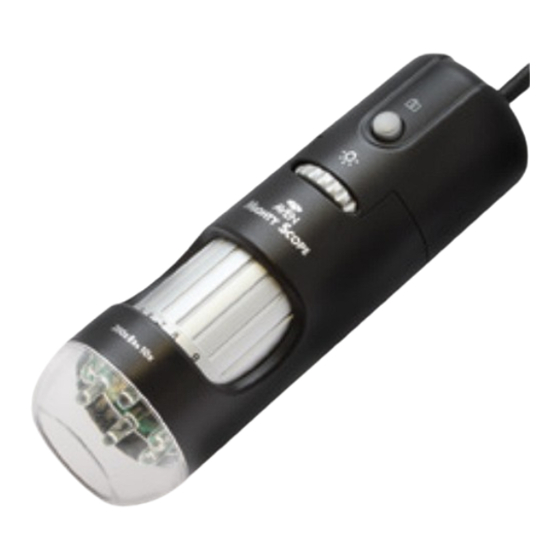
Features Applications The Mighty Scope digital microscope provides a Science Engineering 10~200X adjustable magnification range, and the 500X Work Dermatology model provides 500X(fixed) magnification. The built-in Detailed Repair brightness adjustable LEDs provides proper illumination Assembly of the object. The magnified image can be viewed, Quality Control captured and recorded directly from the computer screen Hobbies... -
Page 4: Pc System Requirements
Pc system requirements Getting started Stand Assembly • Chip set: Pentium 4 3.0GHz CPU or equivalent, AMD Phenom II or above, Northbridge Intel ® i945GZ or above • RAM: 1024MB DDR or above • USB: At least one USB 2.0 •... -
Page 5: Software Installation (Pc)
software installation (PC) 1. Insert the software installation CD into the CD-ROM drive. The installation program will appear automatically on your screen. (If the installation program doesn’t appear, open the MicroViewer folder and double click AutoRun.exe) 2. Click “Install MicroViewer 5MP” button (Fig.1). Connect the scope holder to the vertical post and tighten set-screw... - Page 6 software installation (PC) cont. 3. Install the MicroViewer 5MP program and restart the computer.
-
Page 7: Mighty Scope Controls
Mighty scope controls 4. Connect the Might Scope to the computer (Fig. 2). 5. Double Click the [ MicroViewer 5MP ] software, the start-up screen will show up (Fig. 3). 6. Place the camera on or above the object to be FIG. - Page 8 Mighty scope controls 11. When magnifying an object, adjust the focus knob slightly to the left or right, depending on the working distance, until image is clear (Fig. 9). 12. If the object has too much relief or if a higher FIG.
-
Page 9: Macroviewer Software
MicroViewer software 1. Double click the [ MicroViewer 5MP ] icon on your desktop (Fig. 14). • Make sure the Mighty Scope is plugged into the USB port. FIG. 14 • Key in the Serial Number (which can be found on the outside of the CD envelope) or just press the “Evaluate”... -
Page 10: Compare
MicroViewer Menu Snapshot Zoom in/out Take a picture. Select the zoom-in and zoom-out function on a live image or on (Saved as a BMP file) captured pictures. The maximum Shortcut key: F3 magnification is 6x. The arrow keys *The max resolution for software on the keyboard will move the image. - Page 11 Micro Viewer comparison Mode 1. Plug two microscope USB cables into the PC USB ports (Fig. 17). 2. Click the Compare button, and the compare window will appear on the screen. The live image FIG. 17 shows in the left zone (Fig. 18). *For the best results screen resolution requirement should be at least 1440x900 pixel 1.
- Page 12 MicroViewer – compare Menu 1. Why does the combined Camera 2 picture become distorted Enable/Disable the image when I preview the image? of the second microscope. A: It will distort the image because of the ratio on the Snapshot screen. Please go to the Take a picture.
-
Page 13: Video Setup
Video setup - overview Click the Setup button for the video dialogue box (Fig. 20). 1. Source: User can to choose the image source if there is multiple microscopes connected to the PC. 2. Video Format: Supports three resolution options: 640x480 | 1024x768 | 2048x1536. *Both the Snapshot and Record format will be changed 3. -
Page 14: Preview Picture Mode
Preview – Picture Mode Drag the picture from the list bar to the live zone or just double click the picture in the list bar. The Image will show in the live zone for editing. (Fig. 21). Drawing mode The Drawing mode button opens Microsoft Paint to draw on the picture. - Page 15 Measuring -overview Click the Measurement button to open the measurement window. The image will be frozen. You can calibrate or measure the frozen image (Fig. 22). VGA monitor size: Select the monitor size. H/V ratio: Select the monitor’s correct aspect ratio to insure correct measurements Calibrate: Adjust the calibration.
- Page 16 Measuring - calibration 1. Place a scale under the camera and adjust the focus knob until the image is sharp (Fig. 23). 2. Click the “Snapshot” button to capture the picture, double click this picture in the list bar. 3. Click the “Measurement” button to open the Measurement Window.
- Page 17 Measuring - Angles 1. Click the “Measurement” button to open the Measurement Window. 2. Click the check box next to “Measure.” (Fig. 26) 3. Select the mode “Angle” from the drop down. 4. Set the “Accuracy” to the number of decimal points displayed in the measurement.
- Page 18 Measuring - circle/ellipse 1. Click the “Measurement” button to open the Measurement Window. 2. Check the “Measure” box (Fig. 31). 3. Select the“Circle” Mode for circle or “Ellipse” mode for ellipse. 4. Check the “Cross” function to display crosshairs. FIG. 31 5.
-
Page 19: Measuring
Measuring - line 1. Click the “Measurement” button to open the Measurement Window. 2. Check the “Measure” box. (Fig. 35). 3. Select the “Line” Mode. 4. Hold the right button of the mouse at the first FIG. 35 measurement point. (Fig. 36). 5. - Page 20 Measuring - rectangle 1. Click the “Measurement” button to open the Measurement Window. 2. Check the “Measure” box, 3. Select the “Rectangle” Mode (Fig. 39). 4. Click and hold the right button of the mouse at corner of the object (Fig. 40). FIG.
- Page 21 Measuring - Triangle 1. Click the “Measurement” button to open the Measurement Window. 2. Check the “Measure” box. 3. Select the “Triangle” Mode. (Fig. 43). 4. Click and hold the right button of the mouse at the first point of the object. (Fig. 44). FIG.
- Page 22 Measuring - radius/Arc 1. Click the “Measurement” button to open the Measurement Window. 2. Check the “Measure” box. 3. Select the “3DotRadius” Mode (Fig. 48). 4. Click and hold the right button of the mouse at the first point of the arc (Fig. 49). FIG.
-
Page 23: Software Installation (Mac)
software installation (Mac) 1. Insert the software installation CD into the CD-ROM drive. The installation program will appear automatically on your screen. 2. Click “MicroViewer” icon to install the software. **The Mighty Scope must be plugged into the computer to open and run the MicroViewer software. -
Page 24: Macroviewer Software (Mac)
MicroViewer software (Mac) 1. Double click the [ MicroViewer ] icon on your desktop (Fig. 53). • Make sure the Mighty Scope is plugged into the USB port. 2. The MicroViewer 5MP window will show up and you FIG. 53 should see the live image from the Microscope (Fig. -
Page 25: Compare
MicroViewer Menu (Mac) Snapshot Zoom in/out Take a picture. Select the zoom-in and zoom-out function on captured pictures. (Saved as a JPG file) Record Capture a movie. (Saved as an MOV video file) Setup Compare The setup window. Compare a live image with a (Please see the Video Setup Section for picture or video, compare two more detail) - Page 26 Micro Viewer comparison Mode (Mac) 5. The compare window 1. Plug two microscope USB cables into the USB ports. also supports comparing 2. Click the Compare button and the compare two existing pictures. window will appear on the screen. The live image 6.
- Page 27 Media setup - overview (Mac) Click the Setup button for the media dialogue box (Fig. 57). Default Input: Select the desired video source if there is more than one microscope/camera connected to the computer. Snapshot Format: Choose which size images and videos will be saved at: 640x480 or 1280x1024.
- Page 28 Measuring -overview (Mac) Click the Freeze button to freeze the live image or double click a image in the list bar. The image will be frozen. You can only calibrate or measure the frozen image. Click the Measurement button to open the measurement dialogue window (Fig.
- Page 29 Measuring - calibration (Mac) 1. Place a scale under the camera and adjust the focus knob until the image is sharp (Fig. 59). 2. Click the “Snapshot” button to capture the picture, double click this picture in the list bar. 3.
- Page 30 Measuring - Angles (Mac) 1. Click the “Measurement” button to open the Measurement window. 2. Change the draw mode to “Angle.“ 3. Click the check box next to “Measure.” (Fig. 62) 4. Set the “Accuracy” to the number of decimal FIG.
-
Page 31: Measuring
Measuring - circle/ellipse (Mac) 1. Click the “Measurement” button to open the Measurement Window. 2. Check the “Measure” box (Fig. 67). 3. Select the“Circle” Mode for circle or “Ellipse” mode for ellipse. FIG. 67 4. Click and hold the button of the mouse at the center of the object (Fig. - Page 32 Measuring - line (Mac) 1. Click the “Measurement” button to open the Measurement Window. 2. Check the “Measure” box. (Fig. 71). 3. Select the “Line” Mode. 4. Hold the mouse button at the first measurement FIG. 71 point. (Fig.72). 5. Drag the mouse to the sending point of the measurement (Fig.
- Page 33 Measuring - rectangle (Mac) 1. Click the “Measurement” button to open the Measurement Window. 2. Check the “Measure” box, 3. Select the “Rectangle” Mode (Fig. 75). 4. Click and hold the mouse button at corner of the FIG. 75 object (Fig. 76). 5.
- Page 34 Measuring - Triangle (Mac) 1. Click the “Measurement” button to open the Measurement Window. 2. Check the “Measure” box. 3. Select the “Triangle” Mode. (Fig. 43). 4. Click and hold the mouse button at the first point of the object. (Fig. 44). FIG.
-
Page 35: Faq
Q. After inserting the software installation CD into the CD-ROM drive, Q. After installing the why doesn’t the install start automatically? MicroViewer 5MP, why A: Due to the computer’s system security, many system’s software doesn’t the MicroViewer 1.3M disables the CD-R/USB Auto run function. Please double click program work? A: The version you are running the CD-ROM drive on your computer, and click the... - Page 36 High Performance Precision Tools For MicrocoPy insPecTion & AsseMbly In Industrial , Scientific & Research Applications 4595 Platt Rd Ann Arbor, MI 48108 Tel: 734-973-0099 Fax: 734-973-0097 E-mail: sales@aveninc.com Web: aveninc.com aveninc.com...
Need help?
Do you have a question about the Mighty Scope 5M and is the answer not in the manual?
Questions and answers
Having trouble getting Mighty Scope 5M to run on Win 11 on Win 10 it loads OK.