Electrolux E36DF76EPS Service Manual
30, 36 & 48 inch dual fuel
ranges
Hide thumbs
Also See for E36DF76EPS:
- Use & care manual (44 pages) ,
- Installation instructions manual (36 pages) ,
- Installation instructions manual (36 pages)
Table of Contents
Advertisement
Advertisement
Table of Contents

Subscribe to Our Youtube Channel
Related Manuals for Electrolux E36DF76EPS


Summary of Contents for Electrolux E36DF76EPS
- Page 1 30, 36 & 48 INCH DUAL FUEL RANGES SERVICE MANUAL 5995461133 5/2006...
-
Page 2: Safe Servicing Practices
Electrolux Major Appliances cannot be responsible, nor assume any liability, for injury or damage of any kind arising from the use of this manual. -
Page 3: Table Of Contents
Safe servicing practices Service failure mode Resistance chart Testing the function and temperature selectors Function selector Temperature selector Specifications 30 inch duel fuel freestanding range Smooth glide on racks Four burner, interlocking grates Third element, European convictions system Vantage flame Sealed cooktop spill-basin Control panel features Cooktop... - Page 4 Section A - OWNER’S GUIDE Safety Safety precautions Definitions General precautions Liquefied petroleum (propane) gas conversion Features overview Model features Cooktop features Proper burner adjustments Burner locations Sealed burner configurations Brass burner rings Burn igniters Control knobs Placement of burner grates Flame adjustment Surface cooking Using the griddle...
- Page 5 Gas and electric requirements table Electrical power supply requirements Gas and electrical rough-in Cabinet and countertop preparation Cutout dimensions E36DF76EPS and E48DF76EPS overall dimensions side view E30DF74EPS overall dimensions side view Installing the anti-tip bracket Gas regulator and electrical conduit location Installing optional backguards...
- Page 6 Oven heats in convection bake but convection fan does not operate Oven does not heat in convection bake but the convection fan runs Oven does not heat in convection roast and convection fan does not run Oven does not heat in convection roast but convection fan runs Oven heats in convection roast but convection fan does not operate LEDs do not light One LED does not light...
- Page 7 Removing the smoke eliminator Removing the oven sensor Removing the rack support Removing the oven light Removing the oven latch assembly Removing the pressure regulator Removing the back cover Removing the convection fan motor Removing the air channel cover Removing the air channel Removing the cooling fan assembly Removing the cooling fan assembly cover Removing the remove oven rack switch...
-
Page 8: Service Failure Mode
Service Failure Mode Failure Mode Definition Front Panel LED Failure Description Runaway Temperature Incorrect Micro ID Incorrect EEPROM Checksum Open Temperature Probe Shorted Temperature Probe Max Unlock Time Exceeded (Motor Door Latch) Max Unlock Attempts.Exceeded (Motor Door Latch) Max Lock Time Exceeded (Motor Door Latch) Max Lock Attempts.Exceeded (Motor Door Latch) Motor Door Latch Failed During Clean Operation Inter Processor Communications Failure (Motor Door Latch) -
Page 9: Resistance Chart
Max lock Time Set the oven up for a clean cycle. Does the latch motor turn? exceeded (motor No. Check the voltage applied to the latch motor. If line to neutral, door latch) replace latch mechanism. If zero, replace electronic control board. Yes. -
Page 10: Testing The Function And Temperature Selectors
Testing Function and temperature selectors The function and temperature selectors both use a Piher N-15 10 K ohm pot. Note that the tolerance on this part is 30%, so the measured resistance between pins 1 & 3 will be 10,000 ± 3,000 Ohms. The controller uses a ratiometric approach to determine position so this variation does not affect the software. -
Page 11: Specifications
SPECIFICATIONS Four Burners, Interlocking Grates 30" Dual-Fuel Freestanding Range Designed for cooking multiple dishes at varying temperatures on a single rangetop. Interlocking grates • Product Weight – 260 Lbs. spread weight over a broad area providing an ultrastable cook surface. •... -
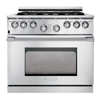
Page 12: Control Panel Features
30" DUAL-FUEL FREESTANDING 12" Stainless Steel – ACCBG12-30 Optional Stainless Steel Kick Plate – KIKPLT30 Optional RANGE SPECIFICATIONS CONTROL PANEL FEATURES Cutout Dimensions – Electronic Oven Control Formed Stainless Steel Platform Large Professional Skirted Knobs with Bezel Height 31-3/4" Width 30-1/16"... - Page 13 Refer to Product Installation Guide for detailed installation instructions on the web at www.electroluxusa.com. High standards of quality at Electrolux Major Appliances mean we are constantly working to improve our products. We reserve the right to change specifications...
-
Page 14: Inch Duel Fuel Freestanding Range
1/8" flame-retardant millboard Electrolux ICON™ freestanding range. The heavy-duty covered with not less than No. 28 MGS sheet steel, 9" shelf provides easy access to and convenient stor- 0.015"... -
Page 15: Control Panel Features
Backsplash 36" DUAL-FUEL FREESTANDING RANGE 9" Stainless Steel – ACCBG09-36 Optional 24" Stainless Steel with 9" CONTROL PANEL FEATURES Shelf – ACCBG24-36 Optional Stainless Steel Kick Plate – KIKPLT36 Optional Electronic Oven Control Formed Stainless Steel Platform SPECIFICATIONS Large Professional Skirted Knobs with Bezel Cutout Dimensions COOKTOP Height... - Page 16 Refer to Product Installation Guide for detailed installation instructions on the web at www.electroluxusa.com. High standards of quality at Electrolux Major Appliances mean we are constantly working to improve our products. We reserve the right to change specifications...
-
Page 17: Inch Duel Fuel Freestanding Range
1/8" flame-retardant millboard Electrolux ICON™ freestanding range. The covered with not less than No. 28 MGS sheet steel, heavy-duty 9" shelf provides easy access to and 0.015"... -
Page 18: Control Panel Features
48" DUAL-FUEL FREESTANDING Black Knobs RANGE Black Burner Knob Optional Black Thermostat Knob Optional CONTROL PANEL FEATURES Black Oven Selection Knob Optional Electronic Oven Control Backsplash Formed Stainless Steel Platform Large Professional Skirted Knobs with Bezel 9" Stainless Steel – ACCBG09-48 Optional 24"... - Page 19 Refer to Product Installation Guide for detailed installation instructions on the web at www.electroluxusa.com. High standards of quality at Electrolux Major Appliances mean we are constantly working to improve our products. We reserve the right to change specifications...
-
Page 20: Sample Wiring Diagram Of The Large Oven Section
Sample wiring diagram of the large oven section Always use the diagram with the product... -
Page 21: Sample Wiring Diagram Of The Small Oven Section
Sample wiring diagram of the small oven section Always use the diagram with the product... -
Page 22: Sample Wiring Diagram Of The Top Burner Section
Sample wiring diagram of the top burner section Always use the diagram with the product... -
Page 23: Section A - Owners Guide
SECTION A - OWNERS GUIDE that you know how and where to turn off power. Also, have the installer show you the location of the gas supply. If you smell gas, do not use the Safety range. Immediately turn off the gas supply at the shut off valve, disconnect electrical power to the unit at the fuse or junction box and contact the IMPORTANT SAFETY INSTRUCTIONS... - Page 24 not extend over adjacent burners. broiler pan and insert, oven racks, rack glides, convection fan filter and any other utensils. • Always check the positions of the control knobs to make sure the cooktop is off when you are • In the event that a burner flame goes out and finished cooking.
-
Page 25: Liquefied Petroleum (Propane) Gas Conversion
clothing or other flammable materials contact The conversion must be performed by a qualified heating elements or interior surfaces of the oven service technician in accordance with the kit until they have had sufficient time to cool. instructions and all local codes and requirements. Failure to follow instructions could result in seri- •... -
Page 26: Features Overview
Feature Overview Before using your range, become familiar with the fea- to some other position and back to “Off”. tures and control panel layout. See drawering below for At this time the range is ready for use. a detailed control panel layout for your model. NOTE: If a power outage occurs, the above noted NOTE: Upon initial power being applied to the test sequence will take place. -
Page 27: Cooktop Features
Cooktop Features BURNER LOCATIONS All Electrolux Icon range cooktops are equipped with PROPER BURNER ADJUSTMENTS sealed burners. Burner configurations vary by the model number of your range. See drawing below for a detailed The color of the flame is the key to proper burner burner layout for your model. -
Page 28: Sealed Burner Configurations
The left two knobs operate the left two burners, and the right two knobs control the two right burners. BURNER BASE On E36DF76EPS and E48DF76EPS ranges, there are BRASS a total of six burners, including two burners rated at a BURNER RING... -
Page 29: Flame Adjustment
IMPORTANT Surface Cooking Do not slide the grates on the stainless steel frame. UTENSILS TO USE FOR BEST Doing so can damage the surface. PERFORMANCE FLAME ADJUSTMENT For most cooking, start on the highest control setting and then turn to a lower one to complete the process. Use the chart below as a guide for determining proper flame size for various types of cooking. -
Page 30: Using The Griddle
Wok. It is recommended that you use the right front POWER burner for model E30DF74EPS or cen- ter front POWER burner for models E36DF76EPS and E48DF76EPS with the wok stand for best perfor- mance. If properly positioned, the Wok Stand will not slide off the grate. -
Page 31: To Properly Position The Wok Stand
NOT be used. The supporting ring was not designed CAUTION on the for proper or stable use Surface Burner Grates. USING THE SIMMER PLATE Always use potholders to remove the wok stand from the grate. Allow the wok stand to cool before removing. - Page 32 Simmer Burner: best used for simmering delicate sauces, etc. Standard Burner: used for most all surface cooking needs. Large Burner: best used when bringing large quantities when preparing larger of liquid to temperature and quantities of food. Regardless of size, always select a utensil that is suitable for the amount and type of food being prepared.
-
Page 33: Operation
Operation IMPORTANT • If the gas does not ignite within four seconds, BEFORE COOKING turn off the valve. Allow at least two minutes for any gas to dissipate, then repeat the lighting Ensure that the range has been installed by a qualified procedure. -
Page 34: Energy Saving Tips
and energy. Follow these recommendations for best results: 1. Use low or medium flame heights when cooking in utensils that are poor conductors of heat, such as glass, ceramic, and cast iron cooking vessels. Reduce the flame height until it covers approximately 1/3 of the utensil diameter. -
Page 35: Getting Started
Getting Started To remove the oven rack support for a self-clean cycle, support and lift front bottom of rack support to release front tabs. Then, rotate rack support up and BEFORE SETTING OVEN CONTROLS out to release rear tabs. If the rack supports are not removed, the self-clean cycle won’t start. -
Page 36: Arranging Oven Racks
RECOMMENDED RACK POSITIONS FOR BROILING, BAKING & ROASTING Food Rack Position Broiling meats, chicken or fish 5, 6 or 7 Cookies, cakes, pies & muffins 3 or 4 Frozen pies, angel food cake, yeast, bread, casseroles, small cuts of meat or poultry Turkey, roast or ham Note: Always use caution when removing food. -
Page 37: Air Circulation In The Oven
The hot air must be able to circulate around the pans and cookware in the oven for even heat to reach around E36DF76EPS the food. COMPANION OVEN ( FOR E48DF76EPS) The E48DF76EPS includes a companion oven, which is a fully featured, selfcleaning, convection oven. -
Page 38: Cooking Instructions
distributes the heated air evenly to ensure uniform results. Temperatures may be set from 170° F to 500° F. Use this function for single rack baking, multiple rack baking, roasting, and preparation of complete meals. Convection Roast - In this combination convection/ra- diant function, the bake, broil and convection elements provide the heat. -
Page 39: Baking Problems
BAKING PROBLEMS For best cooking results preheat the oven before baking cookies, breads, cakes, pies or pastries, etc... There is no need to preheat the oven for roasting meats or baking casseroles. The cooking times and temperatures needed to bake a product may vary slightly from your previous appliance. Baking Problems and Solutions Chart Baking Problems Causes... -
Page 40: Convection Baking
CONVECTION BAKING To change the Convection Bake temperature (example changing from 350°F to 425°F): As a general rule, convection baking will allow prepara- tion of most foods at reduced temperatures for shorter 1 After the oven has already been set at 350°F, periods of time, while producing superior results. -
Page 41: Broiling
3 Poultry should be placed breast side up, on a rack NOTE: THERE IS NO AUTOMATIC PREHEAT WITH in a shallow pan that fits the size of the food. Again, THIS MODE. the broiler pan and insert accompanying the oven can be used. -
Page 42: Broiling Times
Broiling Times ing pan to a different rack position to suit for doneness. If the food you are broiling is not listed in the table, fol- Use the following table for approximate broiling times. low the instructions provided in your cookbook and Increase or decrease broiling times, or move the broil- watch the item closely. -
Page 43: Using The Self-Clean Feature
can cause smoke or a fire when subjected to high tem- Broiler Clean-Up Tips: peratures. DO NOT allow food spills with a high sugar or acid content (such as tomatoes, sauerkraut, fruit To make cleaning easier, line the bottom of the broiler juices or pie filling) to remain on the surface as they pan with aluminum foil. -
Page 44: Cleaning Tips For Range Cooktop
the door to allow hot air or steam to escape. The product. Several materials and finishes are used in the oven may still be VERY HOT. cooktop. Each material and finish must be properly cleaned according to the following recommendations. To start a Self-Cleaning cycle: Failure to follow these recommendations may result in permanent damage to the cooktop. -
Page 45: Cleaning Stainless Steel Surfaces
(If you are un- when reinstalling the knob and knob bezels. able to locate these cleaning compounds, please phone the Electrolux Customer Service Department for a re- The knobs are made of a composite plastic. These com- ferral.) ponents should be washed regularly in warm, soapy water. -
Page 46: Cleaning Burner Rings
Stubborn stains may be removed by applying a metal polishing compound. (If you are unable to locate this type of polishing compound, please phone the Electrolux Customer Service Department for a referral.) CLEANING THE BURNER IGNITERS Under certain cooking or cleaning conditions, your cooktop igniters may become coated with or corroded by food deposits, splattered grease or cleaning agents. -
Page 47: General Cleaning
GENERAL CLEANING Cleaning Various Parts of Your appliance Before cleaning any part of the appliance, be sure all controls are turned OFF and the appliance is COOL. REMOVE SPILLOVERS AND HEAVY SOILING AS SOON AS POSSIBLE. REGULAR CLEANING WILL RE- DUCE THE NUMBER OF MAJOR CLEANINGS LATER. -
Page 48: Oven Light
OVEN LIGHT Your new range has halogen oven lights to enhance the view into the oven. The light assembly consists of a removable lens cover and 20-watt 120VAC halogen bulb (OSRAM - Part Number 64428), as well as a light fixture housing. -
Page 49: Solutions To Common Problems
Solutions to Common Problems PROBLEM POSSIBLE CAUSE SOLUTION Nothing works. Oven is not connected to electrical Have oven connected to a properly power. sized electrical power supply by a qualified technician. Power supply is not energized. Have an electrician check power supply, including the house circuit breaker, wiring and fuses. - Page 50 PROBLEM POSSIBLE CAUSE SOLUTION Burners ignite but flame is Burner ring ports are clogged. Clean burner ring ports with straight- extremely large, distorted or ened paper clip, needle or wire. yellow. Burner ports or burner caps are not Remove and carefully re-install positioned properly.
-
Page 51: Service Failure Mode Definitions
Service Failure Mode definitions Failure Mode Definition Front Panel LED Failure Description Runaway Temperature Incorrect Micro ID Incorrect EEPROM Checksum Open Temperature Probe Shorted Temperature Probe Max Unlock Time Exceeded (Motor Door Latch) Max Unlock Attempts.Exceeded (Motor Door Latch) Max Lock Time Exceeded (Motor Door Latch) Max Lock Attempts.Exceeded (Motor Door Latch) Motor Door Latch Failed During Clean Operation Inter Processor Communications Failure (Motor Door Latch) -
Page 52: Sample Warranty
RANGE WARRANTY Y our range is protected by this warranty n the U.S.A., your appliance is warranted by Electrolux Home Products North America, a division of White Consoli- dated Industries, Inc. We authorize no person to change or add to any of our obligations under this warranty. Our obligations for service and parts under this warranty must be performed by us or an authorized Electrolux Home Products North America servicer. -
Page 53: Section B - Installation Instructions
SECTION B - INSTALLATION • Improper installation, adjustment, alteration, service, or maintenance can cause personal INSTRUCTIONS injury or property damage. Refer to these instructions and the accompanying Use & Care Manual. For assistance or additional information, Safety consult a qualified installer, service agency, manufacturer (dealer), or the gas supplier. -
Page 54: Finding Information
60Hz, 30A Liquid Propane 10” Water Column 11” Water Column 240-4 Natural 4” Water Column 5” Water Column 26.4 Amps E36DF76EPS Wire VAC, (6.3 Kw) 10” Water Column 11” Water Column Liquid Propane 60Hz, 30A 240-4 5” Water Column 4” Water Column Natural 44.2 Amps... -
Page 55: Electrical Power Supply Requirements
NOTE: This range is shipped from the factory locations. For replacement purposes, the pre-set for use with natural gas. For LP location of the existing utilities may be conversion see the accompanying LP utilized provided that they do not Conversion Kit. The electrical information interfere with the sides or rear of the in the table is also located on the serial range. - Page 56 10 inches. • The E36DF76EPS and E48DF76EPS ranges are delivered with a 3” backguard from the factory. 9” and 24” backguards are available as options. The E30DF74EPS range is delivered with a 6”...
-
Page 57: Cutout Dimensions
(both sides) (305mm) (203mm) 25” (635mm) Cutout Dimensions Model “A” “B” E30DF74EPS 36” (914mm) Recommended 30 1/16” (764mm) 30” (762mm) Minimum E36DF76EPS 42” (1067mm) Recommended 36 1/16” (914mm) 36” (914mm) Minimum E48DF76EPS 54” (1372mm) Recommended 48 1/8” (1222mm) 48” (1219mm) Minimum... -
Page 58: E36Df76Eps And E48Df76Eps Overall Dimensions Side View
E36DF76EPS and E48DF76EPS Overall Dimensions Side View 30 3/8” (772 mm) Handle 29 1/8” (740mm) Front Edge of Bullnose 28 1/8” (714mm) Face of Control Panel/Oven Door 26 1/2” (673mm) Rear of Control Panel/Oven Door 9” (229mm) 24” (610mm) Backguard 3”... -
Page 59: E30Df74Eps Overall Dimensions Side View
28 1/4” Handle (718 mm) 27 3/8” Front Edge of Bullnose (693.7mm) 25 5/8” Face of Control Panel/Oven Door (652 mm) 24 18” Rear of Control Panel/Oven Door (612.5mm) 6” (152mm) Backsplash 37” (940mm) 35 3/4” (908mm) -
Page 60: Installing The Anti-Tip Bracket
INSTALLING THE ANTI-TIP BRACKET (FOR 30”, 36” & 48” MODELS) WARNING The 30”, 36” and 48” ranges require an anti-tip device. Before installing the range, you must locate and secure the anti-tip bracket to the floor. - Page 61 INSTALLING THE ANTI-TIP BRACKET (FOR 30”, 36” & 48” MODELS) WARNING The 30”, 36” and 48” ranges require an anti-tip device. Before installing the range, you must locate and secure the anti-tip bracket to the floor.
- Page 62 INSTALLING THE ANTI-TIP BRACKET (FOR 30”, 36” & 48” MODELS) WARNING The 30”, 36” and 48” ranges require an anti-tip device. Before installing the range, you must locate and secure the anti-tip bracket to the floor. Rear Rear Center Leveler 5/16 - 18 x 2 or Equivalent...
-
Page 63: Gas Regulator And Electrical Conduit Location
GAS REGULATOR AND ELECTRICAL CONDUIT LOCATION... -
Page 64: Installing Optional Backguards
OPTIONAL BACKGUARDS Special attention should be given to the lower flange in front of the backguard, which must fit between Your Electrolux IconTM range was shipped with a the stainless steel side panels. backguard in place. These instructions cover the instal- lation of one of the optional backguards. -
Page 65: Removing The Oven Door
RE-INSTALLING THE OVEN DOOR(S) REMOVING THE OVEN DOOR(S) Grasp the oven door on opposite sides and lift it until WARNING the door hinges are aligned with the openings in the oven frame. Holding the door at about a 30° angle from Do not attempt to disengage the hinge catches with the horizontal, slide the hinges into the openings until the door removed from the oven. -
Page 66: Making The Electrical Connections
MAKING THE ELECTRICAL CONNECTION WARNING • Models E30DF74EPS, E36DF76EPS and E48DF76EPS must be connected to a grounded, metallic, permanent wiring system. Alternatively, a grounding conductor should be connected to the grounding terminal or lead on the appliance. Failure to do so may result in an electric shock hazard. -
Page 67: Connecting The Green Appliance Wire To A Grounded
3 Connect the red appliance wire to the red (L2) 2 Connect the white appliance wire to the neutral power supply wire in the junction box. (white) supply wire in the junction box. 3 Connect the black appliance wire to the black (L1) power supply wire in the junction box. -
Page 68: Making The Gas Connection
MAKING THE GAS CONNECTION grate onto the top frame, being certain that the rubber feet are positioned in the locating dimples. Before sliding the range into the cabinet, connect a flex- ible gas connector to the gas shut-off valve previously WARNING installed on the stub out. -
Page 69: Operation
Do not attempt to repair the appliance VERIFYING THE OPERATION yourself. NOTE: REFER TO THE USE AND CARE MANUAL Electrolux is not responsible for service FOR DETAILED INSTRUCTIONS. required to correct a faulty installation. Before beginning the test procedure, ensure that all cooktop control valves are in the “OFF”... -
Page 70: Section C - Theory Of Operation
SECTION C - THEORY OF The conversion kit is shipped in a plastic bag in the broiler pan. The kit contains the installation instructions, OPERATION burner orifices, bypass orifices and the burner removal tool. Gas flow The incoming gas flow is connected to a pressure regu- lator, which is mounted to the rear of the range. - Page 71 The top burner valves are mounted to the manifold pipe flowing through that section of the valve. In the low and control gas flow to the orifice assembly. position the gas flow through the valve is through the bypass orifice, located on the side of the valve. The valves are mounted to the manifold pipe so that the hole in the bottom of the valve is aligned with the The output of the valve is connected to the orifice as-...
- Page 72 When the gas leaves the orifice it passes through the The burner ring is placed in the burner base. The slots air shutter. The moment of the gas passing through in the burner ring, when closed at the top by the burner the air shutter creates a vacuum, which draws air into cap, form the burner ports.
-
Page 73: Top Burner Ignition And Reignition System
Top burner ignition and reignition system When the shaft of the valve is rotated from the off posi- tion the contacts of the igniter switch close and remain closed as long as the burner is on. This connects L1 to The burner ignition and reignition system is made up the module terminal for that burner. -
Page 74: Oven Operation
burner igniter’s each. If the range has six top burners function selector mounted to the console, Ib1 would represent three igniters and Ib2 would repre- sent three igniters. The resistor R1is placed in the cir- cuit to slow down the charging time and control the num- ber of sparks per second. - Page 75 bake element mounted to the rear wall of the oven, convection fan motor mounted to the rear of the oven, broil element mounted to the top of the oven, oven high temp limit mounted between the burner box and the top of the oven, convection element and fan blade mounted to the rear wall of the oven, automatic door locking mechanism mounted between...
-
Page 76: Air Movement In The Oven During Convection Bake And Convection Roast
remove rack switch mounted on the rear of the oven, dropped from the tap, and comparing the two, the con- trol makes up for any variances in the control’s resis- tance. 1 2 3 As the thermostat knob is turned the output from pin (2) changes telling the control what temperature is set. -
Page 77: Cooling Blower Air Movement
the conviction filter into the oven. The air circulates When the door is closed, the grill in the door matches through the oven and is drawn back to the fan blade the grill between the oven and the burner box. Air is through the holes in the side of the fan shield. -
Page 78: The Self-Cleaning Cycle
The air is then exhausted down a channel mounted to the door is locked and to go on with the clean cycle. the rear of the oven to the floor underneath the range. With the oven door locked, electronic oven control pro- vides line to line voltage to the bake element until the temperature in the oven reaches 850°F. -
Page 79: Section D -Troubleingshooting
SECTION D -TROUBLEINGSHOOTING NOTE: Always check the wiring and pin/plug connectors before replacing any component. Index Electrical components will not operate. Flame too large and yellow on top burner. Flame too small on top burner. Flame goes out, when valve is turned to the low position. Top burners, not burning properly. -
Page 80: Electrical Components Will Not Operate
FAILURE CHECK CORRECTION If defective replace the fuse or reset the 1. Check fuse or circuit breaker. Electrical components will not circuit breaker. If good go to step 2 operate. 2. If good check line to neutral and If the voltage readings are correct, there’s line to line voltage, at the range a wiring problem in the range, check the terminal block. -
Page 81: One Top Burner, Not Burning Properly
FAILURE CORRECTION CHECK One top burner, not burning Yes, go to step 2. 1. Is the burner ring and cap properly. installed correctly? No, install burner ring and cap correctly. Yes, remove the restriction or replace the 2. Is the orifice, aluminum tube part. -
Page 82: Oven Does Not Operate In Any Fuction
FAILURE CHECK CORRECTION Oven does not operate in any 1. Are the front panel LEDs Yes, checked service failure mode chart. function. indicating a service failure mode? No, go to step 2 2. With the thermostat and selector Yes, go to step 3. turned off, measure the voltage drop between terminal P13 on No, check the high temp limit and wiring... -
Page 83: Oven Does Not Operate In Bake
FAILURE CHECK CORRECTION Oven temperature off more Yes, go to step 2. Remove power from the range. than 10° Disconnect plug P5 from No, go to the back of the range and check electronic oven control board and measure the resistance the oven sensor. -
Page 84: Oven Does Not Operate In Broil
FAILURE CHECK CORRECTION Oven does not operate in 1. Does the oven heat in any other Yes, go to step 2. broil. function? No, refer to oven does not operate. 2. Disconnect power from the Yes, defective electronic oven control board. range, remove the two screws holding the broil element to the No, replace the broil element. -
Page 85: Oven Does Not Heat In Convection Bake But The Convection Fan Runs
FAILURE CHECK CORRECTION Yes, go to step 2. Oven does not heat in con- 1. Does the oven heat in any other vection bake but the convec- function? No, referred to oven does not operate. tion fan runs. 2. Does the convection element Yes, replace electronic oven control board. -
Page 86: Oven Does Not Heat In Convection Roast But Convection Fan Runs
FAILURE CHECK CORRECTION Oven does not heat in con- 1. Does the oven heat in any other Yes, go to step 2. vection roast but the convec- function? tion fan runs. No, referred to oven does not operate. 2. Does the convection element Yes, replace electronic oven control heat, in the convection bake board. -
Page 87: Oven Does Not Operate In Self-Cleaning
FAILURE CHECK CORRECTION Oven does not operate in self- 1. Are the front panel LEDs Yes, checked service failure mode cleaning. indicating a service failure mode? chart. No, go to step 2 2. Have the oven racks and side glides Yes, go to 3. -
Page 88: Section E - Teardown
2. The burner caps lift off. SECTION E - TEARDOWN This section will describe how to remove components from the range. Unless stated, the procedure will be the same on all models. Unless stated, reverse the procedure to reinstall the component. Always remove electrical power from the range when working in an area where electrical power is present. -
Page 89: Removing The Igniters
2. Using the burner tool, unscrew the brass ring 2. Remove the C clamp, holding the spring and holding the burner head to the burner tube and lift igniter to the burner head. the burner out of the drip pan. 3. -
Page 90: Removing The Knob Bezels
Removing the knob bezels: 3. Remove the (4) screws holding the front of the backsplash to the burner box and lift the backsplash off. 1. Remove the knob. 2. Remove the two screws holding the bezel to the control panel. Removing the spill tray: 1. -
Page 91: Removing The Burner Tube
Removing the burner tube: 2. Using two adjustable or 9/16 inch wrenches, hold the orifice tube with one and turn the air shutter tube off with the other. 1. Remove the spill tray. 2. Using a 5/16 inch driver, removed the two screws holding the burner tube to the burner box. -
Page 92: Removing The Front Spill Tray Support
2. Remove the (4) screws holding the front spill tray 2. Remove (2) screws holding the side support to trim to the front spill tray support. the burner box and lift the support off. Removing the front spill tray support: 1. -
Page 93: Removing The Igniter Module
Removing igniter module: 4. Remove the screw holding a module cover to the side of the range. 1. Disconnect power, remove the spill tray and left rear burner tube. 2. Remove the (6) screws holding the igniter module access panel to the burner box and remove the panel. -
Page 94: Removing The Electronic Oven Control Board
Removing electronic oven control board: 5. Release the electronic oven control board from the mounting bracket by releasing the (10) plastic rivets holding the board to the bracket. 1.Disconnect power, remove the spill tray, left front and rear center burner tube assemblies. 2. -
Page 95: Removing The Oven High Temp Limit
3. Disconnect the wires from the transformer, remove 3. Disconnect the wires from the oven high temp limit, the two screws holding the transformer to the top of remove the two screws holding the oven high temp the oven and lift the transformer out. limit to the top of the oven and lift the oven high temp limit out. -
Page 96: Removing The Oven Door
2. Remove the (2) screws holding the door handle to 2. The oven door seal is held to the inner liner of the the outer door liner. oven door by spring clips and can be pulled straight off. Removing the oven door: Removing the oven door inner liner 1. -
Page 97: Removing The Oven Door Cams And Springs
3. Remove the screw from the bottom of the inner liner and lift the spring cam assembly out of the inner liner. Removing the oven door cams and springs: 1. Remove the inner door liner assembly. 2. Remove the (2) screws holding the spring shield to the inner liner and lift the spring shield off. -
Page 98: Removing The Oven Door Glass Package Shield
Removing the oven door inner glass 2. Remove the (4) screws holding the air baffle to the to the inner glass shield and lift the air baffle off. package: 1. Remove the inner glass package shield and the glass package will lift out. Removing the oven door inner glass package shield: 1. -
Page 99: Removing The Control Panel
2. Remove the (4) screws holding the grill to the 4. Disconnect the wires from the oven light switch. front of the range. 5. Using an 11/32 socket, remove the (2) nuts from the bolts holding the control panel to the manifold 3. -
Page 100: Removing The Interface Board
3. Remove the two screws holding the temperature 3. Remove the two screws holding the function selector to the control mounting plate, push the selector to the control mounting plate, push the control forward and to the side, and pull the control control forward and to the side, and pull the control out. -
Page 101: Removing The Manifold Pipe
2. Remove the top burner igniter switch. 3. Remove the (8) screws holding the manifold access panel to the burner box and remove the panel. 3. Using a 5/8" wrench, disconnect the aluminum tubing from the rear of the valve. 4. -
Page 102: Removing The Bake Element
Removing the convection filter screen: 2. Remove the (3) screws holding the kick panel assembly to the front of the range. 1. Open the oven door. 2. Lift up on the screen to disengage the tabs from the bar. 3. Pull the kick panel forward to disengage the pins from the side panels. -
Page 103: Removing The Convection Baffle
3. Disconnect the (2) wire hangers, holding element 2. Using a 17/32” socket remove the nut holding the to the ceiling of the oven. fan blade to the shaft, by turning it clockwise and lift the fan blade off. CLOCKWISE Removing the convection element: 1. -
Page 104: Removing The Oven Sensor
2. Remove the (2) screws holding the smoke 2. Remove the (2) screws holding the oven sensor to eliminator to the top of the oven and drop the the rear wall of the oven and pull the sensor and the eliminator into the oven. -
Page 105: Removing The Oven Latch Assembly
Removing the pressure regulator access 2. The light cover pulls straight off and the light bulb pulls straight out. panel: 1. Remove the (2) screws holding the pressure regulator access panel to the back cover. Removing the oven door latch assembly: 1. -
Page 106: Removing The Convection Fan Motor
2. Remove the (8) screws, four on each end, holding 3. Using a ¼” nut driver, remove the three screws the back cover to the side panels and lift the back holding the motor to the rear of the oven and pull cover off. -
Page 107: Removing The Air Channel
Removing the rear air channel: 2. Remove the (7) screws holding the cooling fan cover to the rear of the oven. Pull the assembly back and disconnect the wires to the fan motor. 1. Disconnect power, remove the back cover and the rear air channel cover. -
Page 108: Removing The Pressure Regulator
Removing the side panels: 2. Remove the (2) screws holding the switch to the mounting bracket. Drop to switch down and disconnect the wires. 1. Disconnect power and remove the spill tray and backsplash. 2. Remove the kick panel and the (4) screws holding the back cover to the side panel. -
Page 109: Removing The Side Filler (36" Models)
5. Grab the bottom rear corner of the side panel and 2. Remove the (3) screws holding the filler to the burner rotate the side panel counterclockwise until the front box. edge of the side panel is parallel with the edge of the burner box. -
Page 110: Removing The Door Rollers
Removing the door rollers: 3. Using a 1/8” Allen wrench remove the (2) screws holding the roller assembly to the front frame of the oven and remove the roller assembly through the 1. Remove the side panel, and on the 36 inch models access panel. - Page 111 NOTES...
Need help?
Do you have a question about the E36DF76EPS and is the answer not in the manual?
Questions and answers