Sony DSC-F77 Service Manual
Digital still camera
Hide thumbs
Also See for DSC-F77:
- Operating instructions manual (116 pages) ,
- Operating instructions manual (116 pages) ,
- Service manual (37 pages)
Table of Contents
Advertisement
Quick Links
SERVICE MANUAL
Ver 1.1 2003. 02
Revision History
Revision History
Link
Link
SPECIFICATIONS
SPECIFICATIONS
SERVICE NOTE
SERVICE NOTE
DISASSEMBLY
DISASSEMBLY
• For ADJUSTMENTS (SECTION 6), refer to SERVICE MANUAL, ADJ (992999751.pdf).
• For INSTRUCTION MANUAL, refer to SERVICE MANUAL, LEVEL 1 (992999741.pdf).
• Reference No. search on printed wiring boards is available.
• To repair DSC-FX77, make sure to follow the items of "DISASSEMBLING THE HINGE COVER AT REPAIRING
(DSC-FX77)".
On the SY-81 and BT-14 (FX77) boards
This service manual provides the information that is premised the circuit board replacement service and not intended repair
inside the SY-81and BT-14 (FX77) boards.
Therefore, schematic diagram, printed wiring board, waveforms, mounted parts location and electrical parts list of the SY-81
and BT-14 (FX77) boards are not shown.
The following pages are not shown.
Schematic diagram ...................... Pages 4-9 to 4-36
Printed wiring board ..................... Pages 4-47 to 4-52
Waveforms .................................... Pages 4-58 and 4-59
DSC-F77/FX77
Photo: DSC-FX77
BLOCK DIAGRAMS
BLOCK DIAGRAMS
FRAME SCHEMATIC DIAGRAMS
FRAME SCHEMATIC DIAGRAMS
SCHEMATIC DIAGRAMS
SCHEMATIC DIAGRAMS
Mounted parts location ................. Pages 4-61 and 4-62
Electrical parts list ........................ Pages 5-10, 5-12 to 5-18
AEP Model
UK Model
Japanese Model
Hong Kong Model
Australian Model
Chinese Model
Tourist Model
PRINTED WIRING BOARDS
PRINTED WIRING BOARDS
REPAIR PARTS LIST
REPAIR PARTS LIST
DIGITAL STILL CAMERA
2
LEVEL
DSC-F77/FX77
E Model
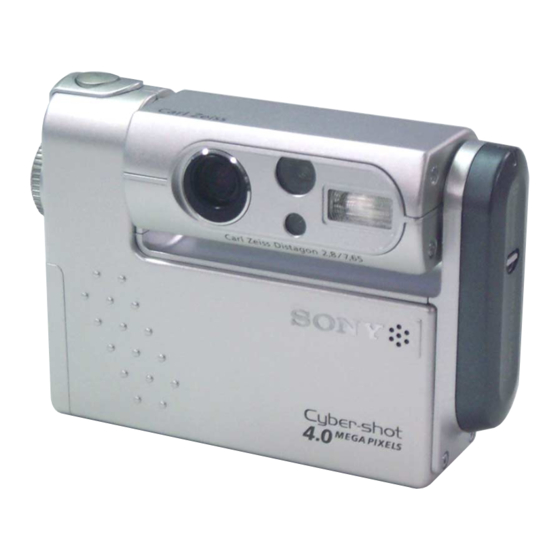
DSC-F77
Advertisement
Table of Contents

Related Manuals for Sony DSC-F77


Summary of Contents for Sony DSC-F77
- Page 1 DSC-F77/FX77 SERVICE MANUAL LEVEL AEP Model Ver 1.1 2003. 02 UK Model Revision History Revision History Japanese Model DSC-F77/FX77 E Model Hong Kong Model Australian Model Chinese Model Tourist Model DSC-F77 Photo: DSC-FX77 Link Link SPECIFICATIONS BLOCK DIAGRAMS PRINTED WIRING BOARDS...
-
Page 2: Specifications
AC 100 to 240 V, 50/60 Hz (W/H/D, protruding portions not included) inches)) Rated output voltage Mass DSC-F77: Approx. 180 g (6.3 oz) F2.8 DC 4.2 V, 1.5 A DSC-FX77: Approx. 185 g (6.5 oz) Exposure control Operating temperature range (NP-FC10 battery pack, “Memory Stick”... - Page 3 COMPONENTS IDENTIFIED BY MARK 0 OR DOTTED LINE WITH MARK 0 ON THE SCHEMATIC DIAGRAMS AND IN THE PARTS LIST ARE CRITICAL TO SAFE OPERATION. REPLACE THESE COMPONENTS WITH SONY PARTS WHOSE PART NUMBERS APPEAR AS SHOWN IN THIS MANUAL OR IN SUPPLEMENTS PUBLISHED BY SONY.
-
Page 4: Table Of Contents
1-3. Description on Self-diagnosis Display ···························· 1-2 1-4. Disassembling the Hing Cover at Repairing (DSC-FX77) ···································································· 1-3 DISASSEMBLY 2-1. Hinge Cover (DSC-F77) ·················································· 2-2 2-2. Hinge Cover, BT-14 Board (DSC-FX77) ························ 2-2 2-3. Cabinet (Front) ································································ 2-3 2-4. Inner Cabinet (Front) ······················································· 2-4 2-5. -
Page 5: Service Note
DSC-F77/FX77 SECTION 1 COVER COVER SERVICE NOTE 1-1. NOTE FOR REPAIR When remove a connector, don’t pull at wire of connector. Make sure that the flat cable and flexible board are not cracked of It is possible that a wire is snapped. -
Page 6: Description On Self-Diagnosis Display
1-3. DESCRIPTION ON SELF-DIAGNOSIS-DISPLAY Self-diagnosis display • C: ss: ss You can reverse the camera malfunction yourself. (However, contact your Sony dealer or local authorized Sony service facility when you cannot recover from the camera malfunction.) • E: ss: ss Contact your Sony dealer or local authorized Sony service facility. -
Page 7: Disassembling The Hing Cover At Repairing
DSC-F77/FX77 1-4. DISASSEMBLING THE HINGE COVER AT REPAIRING (DSC-FX77) Hinge cover When two SPECIAL BIT (P2 MAIN) M1.7 are removed or installed, use ANT DRIVER (D5LUOX113A). ANT DRIVER (J-2507-052-1) Two BIT screws (DSC-FX77) Note: Be sure to use SPECIAL BIT (P2 MAIN) M1.7 (3-079-777-010) at service. -
Page 8: Disassembly
COVER DISASSEMBLY • This following flow shows the disassembly procedure. DSC-F77/FX77 2-2. HINGE COVER, 2-1. HINGE COVER BT-14 BOARD (DSC-FX77) (DSC-F77) (Page 2-2) (Page 2-2) 2-3. CABINET (FRONT) (Page 2-3) 2-4. INNER CABINET (FRONT) (Page 2-4) 2-5. LENS BLOCK ASSEMBLY 2-12. -
Page 9: Hinge Cover (Dsc-F77)
DSC-F77/FX77 Note: Follow the disassembly procedure in the numerical order given. 2-1. HINGE COVER (DSC-F77) 2 Remove the hinge cover (BLT) assembly in the direction of arrow A, and releace four claws. 3 Hinge cover 1 Two screws (M1.7) 2-2. HINGE COVER, BT-14 BOARD (DSC-FX77) -
Page 10: Cabinet (Front)
DSC-F77/FX77 2-3. CABINET (FRONT) -Side view- 1 Screw (M1.7) Rear 4 Open the BT lid 3 Screw (M1.7) in the direction of arrow A. 2 Screw (M1.7) 5 Move the lower part of the cabinet (front) in the direction -Bottom view- of arrow B. -
Page 11: Inner Cabinet (Front)
DSC-F77/FX77 2-4. INNER CABINET (FRONT) Inner cabinet (rear) Two claws Cabinet (front) 2 Inner cabinet (front) 1 Disengage two claws of the inner cabinet (front) with sticking a flat head driver or something similar. 2-5. LENS BLOCK ASSEMBLY 9 Remove the lens block assembly from inner cabinet section in the direction of arrow B. -
Page 12: Cabinet (Rear) Block
DSC-F77/FX77 2-6. CABINET (REAR) BLOCK Note: Be careful not to perform it by force, or the cabinet (front) (inner cabinet (rear)) may be distorted. 4 Pressing the rib (inner cabinet (rear)) in the direction of arrow B, disengage the claw with holding up the cabinet (rear) a little in the direction of arrow C. -
Page 13: Cabinet (Bottom) Assembly
DSC-F77/FX77 2-7. CABINET (BOTTOM) ASSEMBLY 1 Turn the cabinet (bottom) assembly inthe direction of arrow, and releace two claws. 2 Cabinet (bottom) assembly 2-8. CONTROL SWITCH BLOCK 4 Control switch block 3 Flexible board (CN853) 1 Screw (M1.7) -
Page 14: Inner Cabinet (Rear), Kk-29 Board
DSC-F77/FX77 2-9. INNER CABINET (REAR), KK-29 BOARD 2 Flexible board (CN851) Inner cabinet (rear) block 3 Two screws (DIA. 1.7 × 4) 1 Pressing the lower part of the inner cabinet (rear) block in the direction of arrow A, disengage the claw with rotating it in the direction of arrow B. -
Page 15: Sy-81 Board
DSC-F77/FX77 2-11.SY-81 BOARD 9 Screw (M1.7) 8 Screw (M1.7) qs Two screws (M1.7) qa Main frame 0 Claw 3 LCD frame 5 Claw 7 Screw (M1.7) 6 Connector holder 2 Screw (M1.7) 1 Screw (M1.7) qf FP-587 board (CN601) qh Claw... -
Page 16: Lens Block
DSC-F77/FX77 2-12.LENS BLOCK 2 Screw (M1.7) 4 L cabinet (lower) assembly 1 Screw Note: High-voltage cautions (M1.7) (See page 1-1) 8 Lens block 3 Three claws 5 Screw (M1.7) 6 Screw (M1.7) 7 L cabinet (upper) assembly 2-13.CD-415 BOARD, OPTICAL FILTER BLOCK... - Page 17 DSC-F77/FX77 2-14.ST-78 BOARD 8 Hinge block Note: High-voltage cautions (See page 1-1) 9 ST-78 board 7 Two claws ST-78 board 6 Connector (CN101) 2 Lens block assembly 4 Two claws 5 L cabinet assembly (front) 1 Screw (M1.7) [SERVICE POSITION : LENS BLOCK] Setting the "Forced Camera ON mode"...
-
Page 18: Board
DSC-F77/FX77 [SERVICE POSITION : SY-81 BOARD SIDE A] : Contacting surface Lens block SY-81 board Control switch block LCD module AC power DC-IN adaptor Memory stick connector ST-78 board [SERVICE POSITION : SY-81 BOARD SIDE B] : Contacting surface LCD module... -
Page 19: Fp-585 Flexible Board Block
DSC-F77/FX77 2-15.FP-585 FLEXIBLE BOARD BLOCK 2 FP-585 flexible board ( CN001) Lens section 1 Tape (K) Lens section 6 FP-585 flexible board block 5 Connector 4 Remove the FP-585 flexible board block in the direction of arrow. [INSTALLATION OF FP-585 FLEXIBLE BOARD]... - Page 20 DSC-F77/FX77 2-16.CIRCUIT BOARDS LOCATION CD-415 ST-78 KK-29 BT-14 (DSC-FX77) SY-81 ADLEBoard Name Function CD-415 CCD IMAGER KK-29 LENS POSITION ST-78 FLASH DRIVE SY-81 A/D CONVERTER, TIMING GENERATOR, CAMERA DSP, SH DSP, VIDEO, CLOCK GENERATOR, LANS DRIVE, HI CONTROL, AUDIO, LCD DRIVE,...
-
Page 21: Flexible Boards Location
DSC-F77/FX77 2-17.FLEXIBLE BOARDS LOCATION FP-585 FP-587 FP-588 (DSC-FX77) FP-586 2-14E 2-14... -
Page 22: Block Diagrams
DSC-F77/FX77 COVER COVER 3. BLOCK DIAGRAMS Link Link OVERALL BLOCK DIAGRAM (1/2) POWER BLOCK DIAGRAM (1/2) OVERALL BLOCK DIAGRAM (1/2) POWER BLOCK DIAGRAM (1/2) POWER BLOCK DIAGRAM (2/2) OVERALL BLOCK DIAGRAM (2/2) POWER BLOCK DIAGRAM (2/2) OVERALL BLOCK DIAGRAM (2/2) - Page 23 DSC-F77/FX77 SECTION 3 3. BLOCK DIAGRAMS 3. BLOCK DIAGRAMS COVER COVER BLOCK DIAGRAMS 3-1. OVERALL BLOCK DIAGRAM (1/2) ( ) : Number in parenthesis ( ) indicates the division number of schematic diagram where the component is located. SY-81 BOARD (1/2)
- Page 24 DSC-F77/FX77 3. BLOCK DIAGRAMS 3. BLOCK DIAGRAMS COVER COVER 3-2. OVERALL BLOCK DIAGRAM (2/2) ( ) : Number in parenthesis ( ) indicates the division number of schematic diagram where the component is located. SY-81 BOARD (2/2) CN503 BATT UNREG...
- Page 25 DSC-F77/FX77 3. BLOCK DIAGRAMS 3. BLOCK DIAGRAMS COVER COVER 3-3. POWER BLOCK DIAGRAM (1/2) ( ) : Number in parenthesis ( ) indicates the division number of schematic diagram where the component is located. SY-81 BOARD (1/2) F051 BATT UNREG EVER 3.0V...
- Page 26 DSC-F77/FX77 3. BLOCK DIAGRAMS 3. BLOCK DIAGRAMS COVER COVER 3-4. POWER BLOCK DIAGRAM (2/2) ( ) : Number in parenthesis ( ) indicates the division number of schematic diagram where the component is located. DSC-FX77 SY-81 BOARD (2/2) BT-14 BOARD...
-
Page 27: Printed Wiring Boards And Schematic Diagrams
DSC-F77/FX77 4-2. SCHEMATIC DIAGRAMS 4-2. SCHEMATIC DIAGRAMS 4-3. PRINTED WIRING BOARDS 4-3. PRINTED WIRING BOARDS COVER COVER SECTION 4 PRINTED WIRING BOARDS AND SCHEMATIC DIAGRAMS 4-1. FRAME SCHEMATIC DIAGRAM FRAME SCHEMATIC DIAGRAM CAMERA BLOCK ST-78 CD-415 BOARD LENS BOARD BLOCK... - Page 28 DSC-F77/FX77 4-2. SCHEMATIC DIAGRAMS 4-2. SCHEMATIC DIAGRAMS COVER COVER 4-2. SCHEMATIC DIAGRAMS THIS NOTE IS COMMON FOR SCHEMATIC DIAGRAMS (In addition to this, the necessary note is printed in each block) (For schematic diagrams) 1. Connection • All capacitors are in µF unless otherwise noted. pF : µ...
-
Page 29: Schematic Diagrams
DSC-F77/FX77 COVER COVER 4-2. SCHEMATIC DIAGRAMS Link Link CONTROL SWITCH BLOCK CD-415 BOARD CONTROL SWITCH BLOCK CD-415 BOARD (CCD IMAGER) (CCD IMAGER) FP-585 FLEXIBLE BOARD ST-78 BOARD FP-585 FLEXIBLE BOARD ST-78 BOARD (FLASH DRIVE) (FLASH DRIVE) FP-586 FLEXIBLE BOARD KK-29 BOARD... - Page 30 DSC-F77/FX77 4-2. SCHEMATIC DIAGRAMS 4-2. SCHEMATIC DIAGRAMS CD-415 BOARD CD-415 BOARD COVER COVER For Schematic Diagram • Refer to page 4-45 for printed wiring board. • Refer to page 4-57 for waveform. D003 CD-415 BOARD CN001 /CHG D_2.9V CCD IMAGER(CD BLOCK) EVER 3.0V...
- Page 31 Schematic diagrams of the SY-81and BT-14 (FX77) boards are not shown. Pages from 4-9 to 4-36 are not shown.
-
Page 32: Flash Drive)
DSC-F77/FX77 4-2. SCHEMATIC DIAGRAMS 4-2. SCHEMATIC DIAGRAMS ST-78 BOARD ST-78 BOARD COVER COVER For Schematic Diagram • Refer to page 4-53 for printed wiring board. ST-78 BOARD FLASH DRIVE(ST BLOCK) D103 HAU160C030TP LND103 XX MARK:NO MOUNT FLASH UNIT XE_A(H) NO MARK:REC/PB MODE... -
Page 33: Lens Position)
DSC-F77/FX77 4-2. SCHEMATIC DIAGRAMS 4-2. SCHEMATIC DIAGRAMS KK-29 BOARD KK-29 BOARD COVER COVER For Schematic Diagram • Refer to page 4-55 for printed wiring board. CONTROL SWITCH BLOCK(MD51200) KK-29 FLEXIBLE BOARD LENS POSITION(KK BLOCK) CONTROL SWITCH BLOCK(MD51200) is replased as block, so that PRINTED WIRING BOARD is omitted. -
Page 34: Fp-585 Flexible
DSC-F77/FX77 4-2. SCHEMATIC DIAGRAMS 4-2. SCHEMATIC DIAGRAMS FP-586 FLEXIBLE BOARD FP-586 FLEXIBLE BOARD COVER COVER For Schematic Diagram • Refer to page 4-56 for printed wiring board. FP-585 FLEXIBLE BOARD FP-586 FLEXIBLE BOARD FP-585 FLEXIBLE BOARD is replased as block, so that PRINTED WIRING BOARD is omitted. - Page 35 DSC-F77/FX77 4-3. PRINTED WIRING BOARDS 4-3. PRINTED WIRING BOARDS COVER COVER 4-3. PRINTED WIRING BOARDS THIS NOTE IS COMMON FOR WIRING BOARDS (In addition to this, the necessary note is printed in each block) (For printed wiring boards) • Chip parts.
- Page 36 DSC-F77/FX77 COVER COVER 4-3. PRINTED WIRING BOARDS Link Link CD-415 BOARD KK-29 BOARD CD-415 BOARD KK-29 BOARD ST-78 BOARD FP-586 FLEXIBLE BOARD ST-78 BOARD FP-586 FLEXIBLE BOARD COMMON NOTE FOR PRINTED WIRING BOARDS WAVEFORMS COMMON NOTE FOR PRINTED WIRING BOARDS...
- Page 37 DSC-F77/FX77 4-2. SCHEMATIC DIAGRAMS 4-2. SCHEMATIC DIAGRAMS 4-3. PRINTED WIRING BOARDS 4-3. PRINTED WIRING BOARDS MOUNTED PARTS LOCATION MOUNTED PARTS LOCATION COVER COVER CD-415 (CCD IMAGER) For Printed Wiring Board. • :Uses unleaded solder. • CD-415 board is 6-layer print board. However, the pattern of layer 2 to 5 have not been included in the diagram.
- Page 38 Printed wiring boards of the SY-81 and BT-14 (FX77) boards are not shown. Pages from 4-47 to 4-52 are not shown.
- Page 39 DSC-F77/FX77 4-2. SCHEMATIC DIAGRAMS 4-2. SCHEMATIC DIAGRAMS 4-3. PRINTED WIRING BOARDS 4-3. PRINTED WIRING BOARDS MOUNTED PARTS LOCATION MOUNTED PARTS LOCATION COVER COVER ST-78 (FLASH DRIVE) For Printed Wiring Board. • :Uses unleaded solder. • ST-78 board is 8-layer print board. However, the pattern of layers 2 to 7 have not been included in the diagram.
-
Page 40: Fp-586 Flexible
DSC-F77/FX77 4-2. SCHEMATIC DIAGRAMS 4-2. SCHEMATIC DIAGRAMS 4-3. PRINTED WIRING BOARDS 4-3. PRINTED WIRING BOARDS MOUNTED PARTS LOCATION MOUNTED PARTS LOCATION COVER COVER KK-29 (LENS POSITION) FP-586 FLEXIBLE For Printed Wiring Board. For Printed Wiring Board. • :Uses unleaded solder. -
Page 41: Waveforms
DSC-F77/FX77 CD-415 BOARD CD-415 BOARD COVER COVER 4-4. WAVEFORMS CD-415 BOARD 7.6 Vp-p 148 µsec IC001 1, 2, 3 REC 7.6 Vp-p 148 µsec IC001 4, 5, 6 REC 1.0 Vp-p 148 µsec IC001 q; REC 3.6 Vp-p 18 MHz IC001 qs REC 5.1 Vp-p... - Page 42 Waveforms of the SY-81 board are not shown. Pages 4-58 and 4-59 are not shown.
-
Page 43: Mounted Parts Location
DSC-F77/FX77 4-3. PRINTED WIRING BOARDS 4-3. PRINTED WIRING BOARDS COVER COVER 4-5. MOUNTED PARTS LOCATION no mark : side A * mark : side B CD-415 BOARD C001 C002 C003 C004 C005 C006 C007 C008 C010 C011 CN001 A-3 D001... - Page 44 Mounted parts location of the SY-81 board are not shown. Pages 4-61 and 4-62 are not shown.
- Page 45 Ver 1.1 2003. 02 DSC-F77/FX77 4-3. PRINTED WIRING BOARDS 4-3. PRINTED WIRING BOARDS COVER COVER no mark : side A * mark : side B ST-78 BOARD C102 C103 * C104 * C105 * CN101 A-2 D101 * D102 * D103...
-
Page 46: Repair Parts List
DSC-F77/FX77 COVER COVER NOTE NOTE 5. REPAIR PARTS LIST NOTE: Characters A to Z of the electrical parts list indicate location of exploded views in which the desired part is shown. EXPLODED VIEWS EXPLODED VIEWS Link Link OVERALL ASSEMBLY OVERALL ASSEMBLY... - Page 47 DSC-F77/FX77 5. REPAIR PARTS LIST 5. REPAIR PARTS LIST COVER COVER NOTE: • -XX, -X mean standardized parts, so they may have some differences from When indicating parts by reference number, the original one. please include the board name. •...
- Page 48 DSC-F77/FX77 5. REPAIR PARTS LIST 5. REPAIR PARTS LIST COVER COVER 5-1. EXPLODED VIEWS 5-1-1. OVERALL ASSEMBLY (DSC-F77) Main assembly-1 (See page 5-4) Ref. No. Part No. Description Ref. No. Part No. Description 3-078-103-01 CABINET (FRONT) 3-078-127-01 COVER, HINGE 3-057-082-21 SCREW (M1.7), P2...
- Page 49 DSC-F77/FX77 5. REPAIR PARTS LIST 5. REPAIR PARTS LIST COVER COVER 5-1-2. OVERALL ASSEMBLY (DSC-FX77) ns: not supplied Main assembly-1 (See page 5-4) Ref. No. Part No. Description Ref. No. Part No. Description 3-078-103-01 CABINET (FRONT) A-7078-501-A BT-14 BOARD, COMPLETE 3-057-082-21 SCREW (M1.7), P2...
- Page 50 DSC-F77/FX77 5. REPAIR PARTS LIST 5. REPAIR PARTS LIST COVER COVER 5-1-3. CABINET (UPPER) BLOCK ASSEMBLY Lens cabinet assembly (See page 5-5) Main assembly-2 (See page 5-6) MIC901 Ref. No. Part No. Description Ref. No. Part No. Description 3-075-827-01 COVER, CUSHION MICROPHONE 3-914-366-01 SCREW (DIA.
- Page 51 DSC-F77/FX77 5. REPAIR PARTS LIST 5. REPAIR PARTS LIST COVER COVER 5-1-4. LENS CABINET ASSEMBLY IC001 (Note 1) (Note 2) (Note 1) Be sure to read “Precuations for Replacement of CCD Imager” on page 4-8 when changing the CCD imager.
- Page 52 DSC-F77/FX77 Ver 1.1 2003. 02 5. REPAIR PARTS LIST 5. REPAIR PARTS LIST COVER COVER 5-1-5. CABINET (REAR) BLOCK ASSEMBLY ns: not supplied Main assembly-3 (See page 5-7) Ref. No. Part No. Description Ref. No. Part No. Description X-3952-812-1 CABINET (BOTTOM) ASSY 3-057-082-21 SCREW (M1.7), P2...
- Page 53 DSC-F77/FX77 5. REPAIR PARTS LIST 5. REPAIR PARTS LIST COVER COVER 5-1-6. BT BLOCK ASSEMBLY-1 ns: not supplied LCD901 D901 BT901 Main assembly-4 (See page 5-8) The components identified by mark 0 or dotted line with mark 0 are critical for safety.
- Page 54 DSC-F77/FX77 5. REPAIR PARTS LIST 5. REPAIR PARTS LIST COVER COVER 5-1-7. BT BLOCK ASSEMBLY-2 ns: not supplied : BT301 (BATTERY, LITHIUM SECONDARY) Board on the mount position. (See page 4-56.) Ref. No. Part No. Description Ref. No. Part No.
- Page 55 DSC-F77/FX77 5-2. ELECTRICAL PARTS LIST Ref. No. Part No. Description Ref. No. Part No. Description Electrical parts list of the BT-14 board (FX77) is not shown. Pages 5-10 is not shown.
- Page 56 8-719-077-34 DIODE SML-310YTT86 (FLASH/CHG) < DIODE > D004 8-719-077-54 DIODE MA4L11100AS0 D101 8-719-056-23 DIODE MA2S111- (K8).SO < FERRITE BEAD > D102 6-500-432-01 DIODE TLOH9202 (SONY) (SELF TIMER/AF ILLUMINATOR) 0 D103 FB001 1-469-082-21 FERRITE 6-500-237-01 DIODE HAU160C030TP < IC > < COIL >...
- Page 57 DSC-F77/FX77 Ref. No. Part No. Description Ref. No. Part No. Description ACCESSORIES ************ 1-477-487-11 CRADLE UNIT 1-477-488-11 ADAPTOR, AC (EXCEPT CH) 1-477-488-12 ADAPTOR, AC (CH) 1-569-007-11 ADAPTOR, CONVERSION (F77: E, JE) 1-569-008-21 ADAPTOR, CONVERSION 2P (F77: E) 1-696-819-21 CORD, POWER (F77: AUS)
- Page 58 DSC-F77/FX77 2003B0500-1 Sony EMCS Co. 9-929-997-31 ©2003.02 — 68 — Published by DI Customer Center...
- Page 59 DSC-F77/FX77 LEVEL AEP Model SERVICE MANUAL UK Model Japanese Model Ver 1.1 2003. 02 DSC-F77/FX77 E Model Hong Kong Model Australian Model Chinese Model Tourist Model DSC-F77 CORRECTION-1 File this correction with the service manual • Correction of MOUNTED PARTS LOCATION •...
- Page 60 1/16W Ref. No. Part No. Description Ref. No. Part No. Description A-7078-427-A ST-78 BOARD, COMPLETE A-7078-427-A ST-78 BOARD, COMPLETE 5-11 R108 1-218-955-11 RES-CHIP 1.5K 1/16W R108 2003B0500-1 Sony EMCS Co. 9-929-997-91 ©2003.2 — 2 — Published by DI Customer Center...
-
Page 61: Revision History
Reverse 992999732.pdf Revision History S.M. Rev. Ver. Date History Contents issued 2002.10 Official Release — — 2003.02 Correction-1 • Correction of MOUNTED PARTS LOCA- (C1) TION • Correction of repair parts S.M. correction : Page 4-63, Page 5-6, Page 5-11...
Need help?
Do you have a question about the DSC-F77 and is the answer not in the manual?
Questions and answers