
Related Manuals for QSC KLA series


Summary of Contents for QSC KLA series
-
Page 1: User Manual
KLA Series User Manual KLA12 – 12" 2-way Loudspeaker KLA181 – 18" Subwoofer KLA AF12 – Array Frame TD-000319-00-A *TD-000319-00*... -
Page 2: Explanation Of Symbols
EXPLANATION OF SYMBOLS The term “WARNING!” indicates instructions regarding personal safety. If the instructions are not followed the result may be bodily injury or death. The term “CAUTION!” indicates instructions regarding possible damage to physical equipment. If these instructions are not followed, it may result in damage to the equipment that may not be covered under the warranty. -
Page 3: Fcc Statement
Damage to, or loss of any software or data residing on the product is not covered. When providing repair or replacement service, QSC will use reasonable efforts to reinstall the product’s original software configuration and subsequent update releases, but will not provide any recovery or... - Page 4 Suspending the KLA Series Loudspeakers AARNRNG!: Read and follow these instructions carefully. If the loudspeakers are not suspended properly, they could fall, causing personal injury and damage to the equipment. Rules for Suspension • Consult a professional mechanical or structural engineer, licensed in the jurisdiction of the sound system installation, to review, verify, and approve all attachments to the building or structure.
- Page 5 The KLA Series is comprised of two models: the KLA12 12-inch, 2-way loudspeaker and the KLA181 18-inch subwoofer. The KLA12 features a highly efficient 500 W x 500 W power-amp module in a rugged, lightweight ABS enclosure that can be used in multiple configurations using QSC's unique SOLO™...
- Page 6 Features KLA12 — Figure 1 — 1. ABS enclosure 6. M10 installation points (3) 2. Steel grille 7. Tilt-Direct™ dual angle (0° or -9°) pole socket 3. Front power LED 8. Slip-resistant feet 4. Handles 9. Side Rigging Plates 5. Power module...
- Page 7 KLA181 0˚ -9˚ — Figure 2 — — Figure 3 — — Figure 4 — 0˚ — Figure 5 — 1. Baltic Birch enclosure 6. M10 installation points (4) 2. Steel grille 7. Slip-resistant feet 3. Front power LED 8. M20 threaded, 35 mm pole mount 4.
- Page 8 KLA AF12 (Shown as shipped) 1. Rigging pins and lanyard (2) 2. Array extension beam 3. Array frame 4. Feet for KLA181 application 5. Feet for KLA12 application — Figure 6 —...
- Page 9 The KLA12 loudspeakers, when attached together, are a fixed-arcuate line array with splay angles of 18° matching the individual loudspeaker's vertical dispersion angle of 18°. The KLA12 features QSC's SOLO™, allowing you to attach KLA12s together with one person, and no tools.
- Page 10 Attaching a KLA12 to a KLA12 or KLA AF12 Array Frame The KLA12 loudspeakers come with the attaching hooks in the retracted position, indicated by the slide down, and the lever "B" in the down, or locked position as shown in Figure 1.
- Page 11 Attaching a KLA12 to a KLA181 The KLA12 cannot be attached to the top of a KLA181. There are various ways to facilitate attaching a KLA12 to a KLA181, and they vary depending on the specific circumstances. Be sure to use proper rigging techniques, and/or employ a professional engineer.
- Page 12 Separating a KLA12 from a KLA AF12 Array Frame, KLA12, or KLA181 Figure Refer to 1. Safely support the bottom KLA12 in the array. You must support both sides of the loudspeaker, and relieve the weight of the loudspeaker from its latching mechanism in order to separate one loudspeaker from another.
- Page 13 Attaching a KLA181 to a KLA AF12 Array Frame Refer to Figure 18 ROTE!: The KLA AF12 Array Frame must be oriented with the KLA181 feet pointing down as shown in Figure 18. For more detail, refer to Figure 3 on page 8. 1.
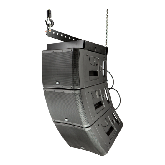
- Page 14 Suspending the KLA Array AARNRNG!: Review the topic "Rules for Suspension" on page 4. The maximum number of KLA 12 Loudspeakers in any array, with or without KLA 181 Loudspeakers, is five. Suspended Loudspeakers per Array Array Configuration Option Maximum Number of KLA181 Loudspeakers Maximum Number of KLA12 Loudspeakers —...
- Page 15 Attach the Rigging Cables to the KLA AF12 Array Frame You can achieve different tilt angles by attaching the suspension cabling to one of the 12 holes in the Extension Bar. The front-to-back orientation of the Extension Bar determines if the array is tilted up or down. As the suspension cabling is moved towards the Extended Portion of the Extension Bar (Figure 21), the tilt angle is increased.
-
Page 16: Audio Connections
1. Adjust the QSC Tilt-Direct™ dual angle pole socket to the zero (default) position or the 9° position. 2. Carefully place one KLA12 on the loudspeaker pole by inserting the pole completely into the QSC Tilt-Direct™ pole socket. Use proper lifting techniques. -
Page 17: Making Audio Connections
Balanced Inputs: Connect to the plug as shown. Unbalanced Inputs: Connect to the plug as shown. 1 = shield (ground) 1 = shield (ground) 3 = minus (-) 3 = jumper to pin 1 2 = plus (+) 2 = plus (+) —... -
Page 18: Power-On Sequence
AARNRNG!: Do not connect more than five KLA Series loudspeakers together using the loop-thru power cables (four loop- thru cables, one AC power cord). If you are using loop-thru power cables, make all loop-thru connections prior to connecting to the AC mains. 3. -
Page 19: Rear Led Indicators
These functions include crossovers, time alignment, limiting and protection, thermal management some of which are implemented using a number of proprietary features. QSC has designed exclusive DSP functions that greatly enhance the capabilities and... -
Page 20: Subwoofer Polarity
Intrinsic Correction™ – Introduced on QSC Concert/Touring products, Intrinsic Correction is a proprietary process and set of signal processing algorithms that address correctable intrinsic characteristics of transducers, waveguides and enclosures. The net result is that any KLA12 system will present extraordinarily even and consistent energy throughout the physical listening area of the loudspeaker, resulting in a very musical, acoustically transparent system. -
Page 21: Additional Features
Additional Features Front LED Switch The blue power LED, on the front of the loudspeakers, may be set to any of three modes by the FRONT LED switch (Figure 33) located on the amplifier panel. PWR – This is the factory setting which means the LED illuminates when the POWER switch is in the ON position and the unit is not in STANDBY. - Page 22 Wiring the Remote Attenuator Single Loudspeaker Multiple Loudspeakers Proper Wiring 1 = +5V 1 2 3 — Figure 38 — Wire the Remote Gain Attenuator as shown in Figure 35. • When using a single potentiometer for a Single Loudspeaker (A). •...
- Page 23 Dimensions KLA12 Side Front 16.6 in (422 mm) 23.4 in (594 mm) — Figure 39 — KLA181 Side Front 25.7 in (653 mm) 23.4 in (594 mm) Side with Optional Casters 30.0 in (762 mm) — Figure 40 —...
-
Page 24: Specifications
Specifications KLA12 KLA181 Configuration 2-way line array element 18" ported subwoofer Transducers Low-frequency 12" cone transducer 18" cone transducer High-frequency 1.75" diaphragm compression driver — Frequency Response (-6 dB) 49 Hz – 18 kHz 38 Hz Frequency Range (-10 dB) 44 Hz –... - Page 25 © 2011 QSC Audio Products, LLC. All rights reserved. QSC™ and the QSC logo are registered trademarks of QSC Audio Products, LLC in the U.S. Patent and Trademark office and other countries. Tilt-Direct, Intrinsic Correction, DEEP and GuardRail are all trademarks of QSC Audio Products, LLC. powerCON is a registered trademark of Neutrik.
Need help?
Do you have a question about the KLA series and is the answer not in the manual?
Questions and answers