
Subscribe to Our Youtube Channel
Related Manuals for Sony CDP-X5000


Summary of Contents for Sony CDP-X5000
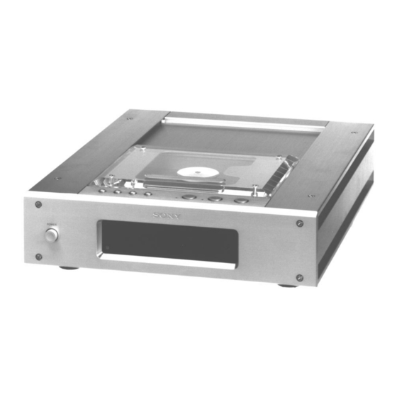
- Page 1 CDP-X5000 SERVICE MANUAL AEP Model UK Model E Model Chinese Model Model Name Using Similar Mechanism Base Unit Type BU-12A Optical Pick-up Type KSS-274A/J-N SPECIFICATIONS General COMPACT DISC PLAYER MICROFILM — 1 —...
-
Page 2: Table Of Contents
DOTTED LINE WITH MARK ! ON THE SCHEMATIC DIAGRAMS AND IN THE PARTS LIST ARE CRITICAL TO SAFE OPERATION. REPLACE THESE COMPO- NENTS WITH SONY PARTS WHOSE PART NUM- BERS APPEAR AS SHOWN IN THIS MANUAL OR IN SUPPLEMENTS PUBLISHED BY SONY. -
Page 3: Servicing Note
SECTION 1 SERVICING NOTE FLUORESCENT INDICATOR TUBE FULL LIGHTING MODE NOTES ON HANDLING THE OPTICAL PICK-UP BLOCK OR BASE UNIT 1. Connect TP (AFJ:Pin 2 of CN515) to GND (Ground), and turn ON the POWER switch. The laser diode in the optical pick-up block may suffer electrostatic 2. -
Page 4: General
SECTION 2 This section is extracted from instruction manual. GENERAL LOCATION OF PARTS AND CONTROLS UNIT OPERATION BLOCK REAR PANEL 4 5 6 7 8 1 LINE OUT 2 DIGITAL OUT OPTICAL switch 3 DIGITAL OUT COAXIAL switch 4 DIGITAL OUT BALANCED switch 5 AC IN (230V) 6 DIGITAL OUT BALANCED 7 DIGITAL OUT COAXIAL... - Page 5 — 5 —...
- Page 6 — 6 —...
- Page 7 — 7 —...
-
Page 8: Disassembly
SECTION 3 DISASSEMBLY Note : Follow the disassembly procedure in the numerical order given. 3-1. TOP PLATE ASSEMBLY 1 Four ornamental screws 2 Top plate assembly 3 Connector (CN805: Display board) 3-2. FRONT PANEL ASSEMBLY 1 Connectors (CN207, CN208: SERVO board) 4 Front panel assembly 2 Two bolts (M3) 3 Two bolts (M3) -
Page 9: Base Unit
3-3. BASE UNIT 4 Four screws (B 2.6X6) 5 Boss (M) (Four pieces) 6 Base unit 1 Connectors (CN201, CN210: SERVO board) 2 Screw (B 3X8) Spring 3 Ground wire 3-4. BACK PANEL 4 Two screws (B 3X6) 2 Screw (B 3X8) 5 Three screws (BV 3X8) 3 Ground wire 6 Back panel assembly... -
Page 10: Electrical Block Adjustments
SECTION 4 ELECTRICAL BLOCK ADJUSTMENTS Note: Note: A clear RF signal waveform means that the shape “◊” can be clearly distinguished at the center of the waveform. 1. CD Block is basically designed to operate without adjustment. Therefore, check each item in order given. RF signal waveform 2. - Page 11 Skew Adjustment (Be sure to perform this adjustment when the optical pick-up or a mechanical part of the optical pick-up has been replaced.) 1. Remove the top plate. (See 3. Disassembly/Top Plate Assembly) 2. Remove the eight screw (+B3X8) of the top plate and remove the KEY board.
-
Page 12: Diagrams
SECTION 5 DIAGRAMS 5-1. CIRCUIT BOARDS LOCATION AC IN board B OUT board BSL board AUDIO board AC SW board KEY board DISPLAY board OUT SW board OPTICAL board S POWER board A OUT board U OUT board FLEXIBLE board SERVO board —... - Page 13 5-2. IC PIN FUNCTIONS • IC101 FOCUS/TRACKING/SLED SERVO/EFM COMPARATOR (CXD2515AQ) Pin No. Pin Name Function SRON Sled drive output (Open) SRDR Sled drive output SFON Sled drive output (Open) TFDR Tracking drive output TRON Tracking drive output (Open) TRDR Tracking drive output TFON Tracking drive output (Not used) FFDR...
- Page 14 Pin No. Pin Name Function – Digital power supply ASYE Asymmetry circuit ON/OFF (Connected to +5V) PSSL Audio data output mode selection input (Connected to Ground) WDCK 48-bit slot D/A interface. Word clock. (Open) LRCK 48-bit slot D/A interface. LR clock. DATA DA 16 output when PSSL=1.48-bit slot serial data when PSSL=0 BCLK...
-
Page 15: Ic Pin Function
Pin No. Pin Name Function XRST System reset DIRC Used in 1-track jump mode (Connected to +5v) SCLK SENS serial data read-out clock DFSW Defect selection pin (Connected to Ground) ATSK Input pin for anti-shock (Connected to Ground) DATA Serial data input, supplied from CPU XLAT Latch input, supplied from CPU CLOK... -
Page 16: Ic201 System Control (Cxp84124-043Q)
• IC201 System Control (CXD84124-043Q) Pin No. Pin Name Function Output of address to S.REM (LH5160T4) Output of write inable to S.REM Not used (Open) LED-PLAY PLAY Lamp output “H”: ON LED-PAUSE PAUSE Lamp output “H”: ON PLAY Open SPDL-MUTE Drive IC MUTE output for spindle. - Page 17 Pin No. Pin Name Function Key data input (A/D input). When the key is not pressed: “H” (Connected to +5V) Key data input (A/D input). When the key is not pressed: “H” Model distinction (Connected to +5V) ADJ/AFJ Test mode input. The equipment is fixed at “H” IN/OUT SW Disc lid Open/Close SCLK...
- Page 18 • Main Ports !¶ SPINDLE MUTE The disc must not move nor sway when the disc lid opens. These problems however occur in the actual case due to the offset volt- age generated and the voltage generated because of the positional relation between the BSL coil and Hall element.
-
Page 23: Exploded Views
SECTION 6 EXPLODED VIEWS NOTE: The components identified by • Items marked “*” are not stocked since they are mark ! or dotted line with mark seldom required for routine service. Some delay ! are critical for safety. should be anticipated when ordering these items. Replace only with part number •... -
Page 24: Front Panel Section
6-2. FRONT PANEL SECTION BU-12A not supplied not supplied not supplied FL801 Ref. No. Part No. Description Remark Ref. No. Part No. Description Remark 3-910-074-31 BOLT (M3) 4-948-375-01 SPRING (F), COIL 4-979-033-01 PANEL, FRONT 4-979-042-01 WINDOW, INDICATION * 61 A-4673-793-A SERVO BOARD, COMPLETE X-4946-608-1 BUTTON ASSY, POWER 4-979-041-01 BOSS (M) 4-960-910-21 SCREW, ORNAMENTAL... -
Page 25: Back Panel Section
6-3. BACK PANEL SECTION not supplied supplied not supplied IC951, IC953 not supplied not supplied not supplied The components identified by mark ! or dotted line with mark ! are critical for safety. Replace only with part number specified. Ref. No. Part No. -
Page 26: Base Unit Section (Bu-12A)
6-4. BASE UNIT SECTION (BU-12A) not supplied not supplied S21,22 The components identified by mark ! or dotted line with mark ! are critical for safety. Replace only with part number specified. Ref. No. Part No. Description Remark Ref. No. Part No. -
Page 27: Electrical Parts List
A OUT AC SW SECTION 7 AC IN AUDIO ELECTRICAL PARTS LIST Note: • Due to standardization, replacements in the parts list • SEMICONDUCTORS The components identified by may be different from the parts specified in the dia- In each case, u: µ , for example: mark ! or dotted line with mark grams or the components used on the set. - Page 28 AUDIO Ref. No. Part No. Description Remark Ref. No. Part No. Description Remark C555 1-164-004-11 CERAMIC CHIP 0.1uF IC503 8-759-296-74 IC AD712JR-REEL C602 1-164-004-11 CERAMIC CHIP 0.1uF IC504 8-759-371-51 IC CXA8042AS C603 1-163-005-11 CERAMIC CHIP 470PF IC551 8-759-242-70 IC TC7WU04F C609 1-136-850-11 FILM 0.1uF...
-
Page 29: Digital Out Balanced
AUDIO B OUT Ref. No. Part No. Description Remark Ref. No. Part No. Description Remark R484 1-259-989-11 CARBON MELF 1/8W R923 1-259-995-11 CARBON MELF 1/8W R486 1-259-980-11 CARBON MELF 1/8W R924 1-249-675-11 CARBON 1.2K 1/2W R487 1-259-975-11 CARBON MELF 1/8W R925 1-249-681-11 CARBON 2.2K... - Page 30 DISPLAY FLEXIBLE OPTICAL OUT SW Ref. No. Part No. Description Remark Ref. No. Part No. Description Remark A-4673-794-A DISPLAY BOARD, COMPLETE A-4673-795-A KEY BOARD, COMPLETE *********************** ******************* 4-969-510-01 HOLDER (FL) < CAPACITOR > 4-971-241-01 CUSHION (FLT) C954 1-163-125-00 CERAMIC CHIP 220PF <...
- Page 31 S POWER SERVO Ref. No. Part No. Description Remark Ref. No. Part No. Description Remark A-4673-792-A S POWER BOARD, COMPLETE A-4673-793-A SERVO BOARD, COMPLETE *********************** ********************* < CAPACITOR > < CAPACITOR > C953 1-130-467-00 MYLAR 470PF C102 1-126-052-11 ELECT 100uF C956 1-163-117-00 CERAMIC CHIP 100PF...
- Page 32 SERVO Ref. No. Part No. Description Remark Ref. No. Part No. Description Remark R110 1-208-462-41 METAL GLAZE 1/10W < CONNECTOR > R111 1-208-774-11 METAL GLAZE 1/10W CN201 1-580-460-11 SOCKET, CONNECTOR 26P R112 1-208-774-11 METAL GLAZE 1/10W * CN207 1-506-503-11 PIN, CONNECTOR 9P R113 1-208-774-11 METAL GLAZE 1/10W...
- Page 33 U OUT SERVO Ref. No. Part No. Description Remark Ref. No. Part No. Description Remark R203 1-216-671-11 METAL CHIP 6.8K 0.5% 1/10W MISCELLANEOUS R204 1-216-671-11 METAL CHIP 6.8K 0.5% 1/10W ************* R205 1-216-671-11 METAL CHIP 6.8K 0.5% 1/10W R206 1-216-671-11 METAL CHIP 6.8K 0.5% 1/10W...
- Page 34 CDP-X5000 English 96F0961-1 Printed in Japan Sony Corporation © 1996. 6 9-960-429-11 Home A&V Products Company Published by Quality Engineering Dept. (Shibaura) — 48 —...
Need help?
Do you have a question about the CDP-X5000 and is the answer not in the manual?
Questions and answers