Table of Contents
Advertisement
Advertisement
Table of Contents

Related Manuals for Datron RT7000


Summary of Contents for Datron RT7000
- Page 1 RT7000-MSOP RT7000 HF SSB Transceiver Operator Manual Datron World Communications Inc. Manual Part No. RT7000-MSOP Release Date: June 2007 Revision: F 3030 Enterprise Court Vista, CA 92081, U.S.A. Phone: (760) 597-1500 Fax: (760) 597-1510 E-Mail: sales@dtwc.com www.dtwc.com...
- Page 3 Change Description Date of Revision Pages Description of Changes Revision Letter Affected 6/2007 Reformatted and updated with inclusion of 1-4, 3-13, addendum 966001 (LQA Scoring) and the FALC 3-16 option. RT7000-MSOP...
- Page 5 Software, documentation, and All rights reserved. any copies of each to Datron. This Software is licensed “AS IS” and Datron provides a war- Datron World Communications, Inc. ranty that covers the media upon which the Software is embed- This manual, as well as the software described in it, is ded for a period of 30 days from receipt of the product.
-
Page 6: Safety Considerations
Remedies: Buyer’s sole remedies and the entire liability of Datron are set forth above. In no event will Datron be liable to Buyer or any other person for any damages, including any incidental or consequential damages,... -
Page 7: Table Of Contents
Powering the RT7000 ........ - Page 8 Field-Level Servicing ..........4-2 RT7000-MSOP...
-
Page 9: Chapter 1: Introduction
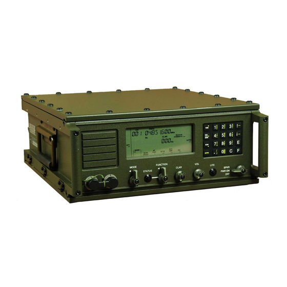
The RT7000 The RT7000 transceiver provides a complete range of voice and data operation over the entire 1.6 to 30 MHz HF spectrum. The RT7000 is microprocessor- controlled and features a state-of-the-art DDS-based synthesizer. An LCD provides channel and frequency data, feedback on other front panel control functions, BITE information and order-wire text messages. -
Page 10: Technical Specifications
25A. Good performance is achieved when the input voltage is in the range of 11 to 15.5V. The RT7000-28 is powered from any DC source providing +28 Vdc at a maximum of 15A (a range of 22 to 30 Vdc). -
Page 11: Rt7000 Variations
5W into 4 ohm; 0 dBm into 600 ohms RT7000 Variations This manual provides information necessary to operate any variation of the RT7000. Options described here may not be available on your transceiver. For more information about these variations, contact Datron. RT7000C Designed for computer control. -
Page 12: Internal Options
RT7000, excluding transmit features. RT7000TX Transmitter only. It includes the full transmitter functions of the RT7000, excluding receiver features. Internal Options Several internal options are available for the RT7000. 7000ACH Additional channels. Increases operational channel capacity to 1000. 7000ALE FED-STD-1045 compatible adaptive system. Provides... -
Page 13: Conventions
Wideband data filter providing 300 to 3300 Hz with tailored group delay characteristics for data operation. RT7000AIRSELCALL Operating with N-1304A (or equivalent) SELCAL devices and Datron power amplifiers, it adds a secondary control line to the radio and allows use of the ICAO-mandated ground-to-air SELCAL 3-tone system. Conventions Bold type is used to denote all items that appear in the display area and for any button, knob or connector used on the front or rear panel. -
Page 15: Chapter 2: Installation
Make sure the temperature at the location is within the specified range, and that there is adequate ventilation around the rear of the RT7000 to allow for air flow. The RT7000 has a rear panel heat sink to dissipate heat that is generated from the power amplifier during transmission. -
Page 16: Front Panel Connections
Two 6-pin microphone connectors on the front panel are wired in parallel and suitable for use by various audio accessories. Audio Connectors Figure 2-1. Front Panel Connections Low-level audio accessories for use with the RT7000 include the following: Part Description Heavy duty hand microphone U.S. MIL-STYLE H-189/U handset... -
Page 17: Rear Panel Connections
2: Installation Rear Panel Connections The rear panel of the RT7000 is made of die cast aluminum and is attached to the rear side panels by 4 hex head bolts. The heat sink maintains the temperature within operational specifications eliminating the need for an internal cooling fan. - Page 18 The waterproof fuse holder (pin 630005) on the rear panel contains either a 25A (12V), 3-AG fuse or 15A (28V), 3-AG fuse. The RT7000 is designed to work into a 50 ohm RF impedance. The output RF Antenna antenna connector is a type N connector. Broadband antennas and dipoles can...
- Page 19 AT/RAT7000B and RAT1000B. Tuners The AT/RAT100 and RAT1000A and RAT1000C connect to Accessory 2. The AT/RAT7000 uses Accessory 3. The RT7000 interfaces with its own line of data terminals or to other external Data Terminal units using Accessories 1 and 2. Interface...
-
Page 20: Figure 2-3. Power Cabling Accessories
2: Installation RT7000-12/28 ANTENNA INPUT FUSE REM ACC3 ACC2 ACC1 RA1000D C991556 C991511 F1 F2 GND DC Power Source UPF7000-12/28 C992034 US 110 220V 50/60Hz C992139 US 220 Power Source 110/220 50/60Hz RA400 RT7201 Power Source RF OUTPUT RF INPUT... -
Page 21: Figure 2-4. Rf Cabling Accessories
2: Installation C991559 RAT7000B C991620 RT7000-12/28 RAT1000C C991505 ANTENNA INPUT FUSE REM ACC3 ACC2 ACC1 RA1000D C991505 C991526 F1 F2 GND RA400 RA400 C991510 RF OUTPUT RF INPUT DC IN DC OUT CONTROL CONTROL CONTROL F1 F2 GND Figure 2-4. RF Cabling Accessories... -
Page 22: Figure 2-5. Control Cabling Accessories
2: Installation Options RAT7000B C992142 RT7000-12/28 RA1000D ANTENNA INPUT FUSE REM ACC3 ACC2 ACC1 F1 F2 GND C992216 C991933 To Front Panel Connector Control C992306 C991552 C991943 RAT1000C RT7201 Radio Access Tuner RAT1000P RA400 RA400 RF OUTPUT RF INPUT C991925... -
Page 23: Operations Check
EIA Data Interface Standards on page 2-4. Remove the front panel of the RT7000 and replace it with a line driver panel Extended Front (RT7000E) to control it remotely. This special version of the radio is used to Panel Control control operations from distances up to 50 feet. -
Page 25: Chapter 3: Operation
Radio Control 2 operator manual (RC2-MSOP); the 7000ALE option must be installed in the radio. Powering the RT7000 Use the PWR ON knob to turn on the RT7000. The version level of the installed software is displayed. Display: RT7000 VER 701xx (where xx is the version level) The BITE system runs automatically and indicates that everything is functional. -
Page 26: Using Knobs, Buttons And Indicators
"Front Panel Features" on page 3-1. The PWR ON knob is a three-position switch that provides DC power to the Power/Speaker RT7000. It is also used to turn the speaker on or off. The positions are: Power off PWR ON... - Page 27 The icon also stops flashing if no changes are entered after a time-out of 10 seconds. Select an operational mode by turning the MODE knob left or right. Possible Mode Select operating modes for the RT7000 are: Mode Description Upper sideband voice, standard voice grade IF filter and...
- Page 28 To select a frequency, press F. • To save entered data, press E. If the AT/RAT7000B or RAT1000C antenna tuner is connected to the RT7000, Tune pressing the TUNE button activates the tune cycle. Turn the FUNCTION knob until the ALE, TCSC, or TA icon is flashing.
- Page 29 Amplifier amplifier. To automatically set and lock RF power in the H (high power) position, set it to ON. To restore control, set it to OFF and the RT7000 no longer requires an external amplifier. Turn the FUNCTION knob until the SQ icon flashes. Press STATUS to...
-
Page 30: Using Menus To Change Settings
3: Operation Using Menus to Change Settings The RT7000 provides menus for adjusting settings. The Alpha menu is for changing settings specific to the 7000TC option (Transcall, Selcall, and TransAdapt). The Alpha menu also allows you to access the ALE submenu which provides its own set of functions for changing settings specific to the ALE option. - Page 31 FREQ INC HZ (frequency increment from 1 Hz to 10 MHz) TEST REAR PANEL I/O (factory test) ENC PASSWORD (Encryption menu) PTT TIMER (sets maximum PTT time) PRINTER CLONE RADIO GLOBAL POSITION SYSTEM (optional) CW HOLD TIME SPLIT SITE (2 radios: TX and RX) CLARIFIER ON/OFF RT7000-MSOP...
- Page 32 (L, M, or H). 2. Press ALPHA 5 and E. The current power level is displayed. CW key the RT7000 and scroll to the power level indicated on the power meter. When the desired power level is achieved, press E.
- Page 33 ALPHA 2 and ALPHA 3. The default is set to scan group 00. Also use the SCAN GROUP icon on the front Note: panel to select a 7000TC scan group (provided ALE is OFF or not installed). RT7000-MSOP...
- Page 34 (23) COM 2 BAUD Allows you to configure the RT7000 COM2 port if you are working from a computer. Use the arrow buttons to scroll through and enter the baud rate, data bits, stop bits and parity.
- Page 35 Entering 0 sets it to OFF (no time-out). The default is 300 seconds. (29) PRINTER Automatically prints complete channel information for the RT7000 if an external printer is connected. (30) CLONE RADIO Allows cloning of another transceiver by downloading all frequency and channel settings.
-
Page 36: Table 3-2. Ale Submenu
BER THRSD (Bit Error Rate threshold) GOLAY THD (Golay threshold) ERR THRSD (error threshold) MESSG OUT (message out) NEW MESSG (new message) MESSG IN (message in) HANDSHAKE NET ADRS (network address) NET NAME (network name) NET SLOT (network slot) 3-12 RT7000-MSOP... - Page 37 (5) SELF ADRS. Any existing address name is briefly displayed. Use the alpha char- acters on the keypad to enter from 3 to 15 characters (no spaces or punctuation). To delete a name enter three periods (...). RT7000-MSOP 3-13...
- Page 38 For indicating if you want the radio to automatically add the address of any station ALE hears to the list of approved other addresses Enter 1 for OFF and 2 for ON, or use the arrows to toggle between OFF and ON. 3-14 RT7000-MSOP...
- Page 39 For selecting an incoming message for review (from 0 to 9). Messages are deleted when a tenth message is received. (26) HANDSHAKE For setting the message exchange compatibility with other radios. Enter 1 for NO Tx, or 2 for NO Rx. RT7000-MSOP 3-15...
- Page 40 Other address by this radio with a range of 1 to 9. The second score position is an analysis of this radio with a possible range of 1 to 9. Scroll through the channels to view their scores. (33) EXIT MENU Exits the ALE submenu. 3-16 RT7000-MSOP...
- Page 41 3: Operation Programming Channels and Frequencies The RT7000 associates a frequency, mode, clarifier status and offset value (if on) to each channel number. These can be different for each channel and can be viewed whenever you enter that channel number. Once frequencies are set to channels, you can assign those channels to scan groups.
- Page 42 If you enter any number after pressing F, the existing frequency Note: changes. To automatically limit a channel to a receive-only operation, enter ALPHA 8. Assigning RX To convert the channel back to a standard RX/TX channel, enter ALPHA 18. Only Channels 3-18 RT7000-MSOP...
-
Page 43: Scanning (For Ta/Tc Only)
Data is retained in the manual channel. Scanning (for TA/TC only) Scan groups are arranged in the RT7000 according to number. You can have up to 32 different scan groups in the transceiver at one time, each one having a different scan group number. - Page 44 Press SCAN to start scanning within the selected scan group. Scanning begins To Start and with the first channel in the selected scan group and continues in numerical Stop Scanning order as each channel number is displayed. Press SCAN again to stop the scanning process. 3-20 RT7000-MSOP...
-
Page 45: Placing An Ale Call
AMD MSG if you are not sending a message. Use function 24 from the ALE menu to create a new message. Note: 10. Press CALL/SEND to attempt the ALE call. Display: ALE LINK xxx (where xxx is the channel selected) RT7000-MSOP 3-21... -
Page 46: Placing A Transadapt, Transcall Or Selcall
Enter the receive call code and press E. The number must be from 001 to 255 and not assigned to another transceiver. Display: xxx (briefly shows the new receive code) To start a Selcall, set the RT7000 to a fixed channel (not scanning). Selcall 1. Turn the FUNCTION knob until the TCSC icon flashes. - Page 47 Press CALL/SEND again. The RT7000 is now under full control of the Transcall circuit. The RT7000 starts transmission on each of the ten channels until it is synchronized with the station to call. When synchronized, both transceivers step through each channel by making a short transmission until the best available channel is reached.
-
Page 48: Activating The Noise Blanker
3: Operation The RT7000 can be on a fixed channel or in scan mode. On a fixed channel, TransAdapt TransAdapt operates the same as Selcall. In scan mode, TransAdapt locates the first usable frequency, not the best. 1. Turn the FUNCTION knob until the TA icon flashes. -
Page 49: Activating Voice Enhancement
Display: OPTION 1 TYPE x (briefly displays last mode entered) Enter the mode (1 or 2) and press E. To verify that the 7000VEM option is installed, look for Note: OPT 1 MODULE to be displayed during start-up. 3-25 RT7000-MSOP... -
Page 51: Routine Maintenance
10,000W on 5, 10 and 15 MHz). This enables regular checks of the frequency calibration. Keep the exterior of the RT7000 clean by wiping it with a damp cloth and polishing it with a soft dry cloth. Make sure all knobs are secure and connectors tight. -
Page 52: Figure 4-1. Board Locations
4: Servicing The front panel assembly is attached to the RT7000 with four screws and a single ribbon cable. RF Amplifier Front Panel RF Filter Processor DC-DC Convertor Display (28V only) Keypad Interface/ Power Supply Motherboard Figure 4-1. Board Locations Field-Level Servicing The transceiver BITE system is designed to identify a faulty board. - Page 53 001-01101 Processor board 001-01300 ALE board 001-01200 Squelch board 004-28100 DC-DC converter (28V) Datron offers the following maintenance tools to facilitate servicing the RT7000. Part Number Description RT7000TK Tool kit with card puller SMTRK Surface mount technology tool kit 7000EXT...
Need help?
Do you have a question about the RT7000 and is the answer not in the manual?
Questions and answers
How to switch ON/OFF channels
To switch a channel to receive-only (OFF for transmit), enter ALPHA 8.
To switch it back to a standard RX/TX (ON for transmit), enter ALPHA 18.
This answer is automatically generated
@Mr. Anderson let's say I want my scan group to 11-19 and all channels are on but I want to operate from 11 to 19 how do I switch off 1 to 10 and 20 to 100
How to install frequency
To install a frequency on the Datron RT7000, follow these steps:
1. Press C, enter the 3-digit channel number, and press E.
2. Press F, enter the receive frequency, and press E.
3. Press F again, enter the transmit frequency, and press E.
4. The new channel frequency is displayed.
5. Press F to toggle between the receive and transmit frequencies if needed.
Example: To set an RX frequency of 21.2 MHz and a TX frequency of 29.3 MHz on channel 41:
1. Press C, 41, and E.
2. Press F, enter 21.2, and press E.
3. Press F, enter 29.3, and press E.
The new frequencies are now stored.
This answer is automatically generated