Table of Contents
Advertisement
Advertisement
Table of Contents

Related Manuals for Datron TW7000


Summary of Contents for Datron TW7000
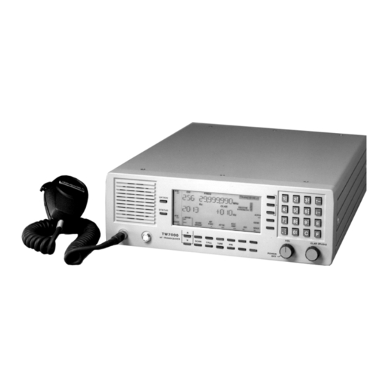
- Page 1 TW7000-MSOP TW7000 HF TRANSCEIVER OPERATOR MANUAL Datron World Communications Inc. 3030 Enterprise Court Manual Part No. TW7000-MSOP Vista, CA 92083, U.S.A Release Date: June 2001 Phone: (760) 597-1500 Fax: (760) 597-1510 Revision: F E-mail: sales@dtwc.com www.dtwc.com...
- Page 3 Datron. Datron World Communication Inc. This Software is licensed “AS IS” and Datron provides a warranty that covers the media upon which the Software This manual, as well as the software described in it, is...
- Page 4 Remedies: Buyer’s sole remedies and the entire liability POSE, AND DATRON EXPRESSLY DISCLAIMS of Datron are set forth above. In no event will Datron be ALL WARRANTIES NOT STATED HEREIN. liable to Buyer or any other person for any damages,...
-
Page 5: Table Of Contents
TW7000 Technical Specifications ....1-2 TW7000 Variations......1-4 Conventions . - Page 6 Customizing Channel and Frequency ....3-16 Scanning ........3-18 Placing an ALE Call .
-
Page 7: General
A custom LCD is used to provide channel and frequency data, feedback on other front panel control functions, BITE informa- tion, and order-wire text messages. The TW7000 has continuous tun- ing and up to 1000 memory channels that can be arranged in multiple scan groups. -
Page 8: Description Of Equipment
The accessories are a dc power cable (C991829), an operator manual (TW7000-MSOP), and two spare dc 25A fuses (550011). The TW7000 is powered from any dc source that provides 13.8V at a maximum of 25A. Good performance is achieved when the input volt- age is in the range of 11 to 15.5V. - Page 9 Table 1-1 TW7000 Technical Specifications Characteristic Specification Input Power Reverse polarity, transient and under/over Protection voltage Size (H x W x D) 4 in. x 13 in. x 17 in. (10.2 cm x 33 cm x 43 cm) Weight 21 lbs. (9.5 kg)
-
Page 10: Tw7000 Variations
TW7000 Variations This manual includes the information necessary to operate any varia- tions of the TW7000. Options described in this manual may not be available on your transceiver. For more information about TW7000 variation, contact DWC. TW7000C: The TW7000C is designed for computer control. The standard front panel is replaced with a blank front panel. - Page 11 TW7000TX: The TW7000TX is a transmitter only. It includes the full transmitter functions of the TW7000, excluding the receiver fea- tures. TW7000 Internal Options Several internal options are available for the TW7000. These include the following: 7000ACH: Increases operational channels to 1000.
-
Page 12: Conventions
Press C, 041, and E. Display: CH FREQ 041 13.330,000 MHz Press ALPHA and 17. Press STATUS. Referenced Manuals • TW7000 HF Transceiver Technical Manual (TW7000-MS) • 7000ALE Radio Control Program Operator Manual (7000ALE-MSOP) • 7000-Series High-Level Encryption Operator Manual (7000ENCR-MSOP) •... -
Page 13: Introduction
Type of Installation The TW7000 can be installed in a variety of different ways. Proper installation is particularly important in marine and vehicular installa- tions; mounting and power source connections can make a difference to transceiver performance. -
Page 14: Antenna Connection
Antenna Connection The TW7000 is designed to work into a 50 ohm, RF impedance. The output RF connector (antenna) is a PL259 UHF-type connector. Broadband antennas and dipoles can be connected directly to this out- put, while high-power amplifiers and antenna tuners use DWC spe- cially designed 50 ohm cables. -
Page 15: Accessory Connections
TX audio CW key line +12 Vdc Accessory Connections DWC has a variety of external accessories for use with the TW7000. For some of these accessories and their control cabling, refer to the Control Cabling Accessories figure on page 2-12. -
Page 16: Accessory Connector 2 Pinouts
Table 2-1 Accessory Connector 1 Pinouts Pin Number Description AUXPTT\ Select Busy +12V ACC EXTCWKEY (external CW key) Strobe Data 0 Data 1 Data 2 Data 3 Data 4 Data 5 Data 6 Data 7 ACK (acknowledge) DI/OSEL Table 2-2 Accessory Connector 2 Pinouts Pin Number Description... -
Page 17: Accessory Connector 3 Pinouts
Table 2-2 Accessory Connector 2 Pinouts Pin Number Description +12V ACC Ground EXTCWKEY (external CW key) ACHKTUNE (tuner check tune) ADATA (tuner data) ACLOCK (tuner clock) ASTROBE (tuner strobe) TC/SCALM (alarm) RETX\ (retransmit) EXTSPKR (speaker audio) SQA (squelch audio) +12V ACC +12V ACC Table 2-3 Accessory Connector 3 Pinouts... - Page 18 TW7000 including their pinouts. External Encryption An embedded encryption board (7000ENCR option) can be installed into the TW7000. External encryption can also be used with the trans- ceiver and connected to Accessory 1 or Accessory 2 using the follow- ing pins:...
- Page 19 AUXPTT\ +12V ACC EIA Data Interface Standards The TW7000 interfaces with a variety of data communications equip- ment (DCE) or data terminal equipment (DTE) using EIA standards RS232, RS422, or RS485. Accessory 1 is configured to provide the standard I/O port (COM1) for these interfaces. The RS232 protocol is standard, all others are optional.
- Page 20 ATURX (tuner RX data) +12V ACC +12V ACC Data Terminal Interface The TW7000 can interface with its own line of computers (TW9200, DT9400, and RT9300) or to other external units using Accessory 1 with the following connections: Pin Number Description...
- Page 21 External Printers A standard parallel printer is plugged into Accessory 1 and used to obtain a hard copy of text messages stored in the transceiver. Pins used on Accessory 1 are as follows: Pin Number Description Ground Select Busy Strobe Data 0 Data 1 Data 2...
-
Page 22: Power Cabling Accessories
BROADBAND TW7000 TRANSCEIVER ANTENNA WHIP ANTENNA TW1000B AMPLIFIER AT7000B ANTENNA TUNER C991938 PS1000SWA TW500B AMPLIFIER 12VDC POWER SOURCE SWR1000 C991829 TW7201E MICROPHONE REMOTE CONTROL TWPP CONNECTS ONLY TO PORTABLE POWER SOURCE THE TW7000E C991830 C991890 REMOTE CONTROL MICROPHONE PF3000 For FSK VOICE/CW &... -
Page 23: Rf Cabling Accessories
TW7000 TRANSCEIVER BROADBAND TW110A ANTENNA HIGH SPEED MODEM 115/230 VAC 50/60 Hz TW5300 DATA MODEM WHIP ANTENNA TW1000B AMPLIFIER BROADBAND AT7000B ANTENNA ANTENNA TUNER C991559 C991539 C991526 RA-PAS ANTENNA RAT1000 ANTENNA TUNER C991526 TW500B BROADBAND AMPLIFIER ANTENNA C991539 RF OUT... -
Page 24: Control Cabling Accessories
TW110A BROADBAND HIGH SPEED MODEM ANTENNA TW7000 TRANSCEIVER WHIP ANTENNA TW5300 115/230 VAC DATA MODEM 50/60 Hz C992143 AT7000B ANTENNA TUNER TW1000B AMPLIFIER 12 Vdc RAT1000 ANTENNA TUNER TW500B C991830 (E) AMPLIFIER MICROPHONE MICROPHONE TW7201E REMOTE CONTROL C992307 TW5300 MODEM... -
Page 25: Remote Control
2 using the following pins: Pin Number Description Ground EXTSPKR (speaker audio) External High-Power Amplifiers The TW7000 interfaces with all existing DWC high-power RF ampli- fiers at Accessory 3 using the following pins: Pin Number Description Ground Ground FILTG\... - Page 26 Extended Front Panel Control The front panel of the TW7000 can be removed from the body of the transceiver and replaced with a line driver panel (TW7000E). This variation of the radio is used to remotely control operations from dis- tances up to 50 feet.
-
Page 27: Tw7000 Back Panel
Figure 2-4 TW7000 Back Panel Installation 2-15... - Page 28 This page intentionally left blank. 2-16 Remote Control...
-
Page 29: Powering The Tw7000
SECTION 3: OPERATION Powering the TW7000 The Power/Volume knob is used to turn on the TW7000. When the radio is on, the version level of the software displays. Display: TW7000 VER701xx (where xx is the version level) The BITE system runs automatically and verifies that the boards are functional. -
Page 30: Knobs, Buttons, And Indicators
Knobs, Buttons, and Indicators The front panel of the TW7000 is designed to be easy to use. Knobs, buttons, and indicators on the display are used to guide operation. Advanced features are easily accessed from menus. Power/Volume Knob The OFF/POWER/VOL control is a rotary knob with power off in the full counterclockwise position. - Page 31 To enter a space, press any bracketed key followed by 0. To delete a character, use the left and right arrows to position the cur- sor and press the C button. All trailing characters move to the left. The up and down arrows are used to scroll through the menu selec- tions.
- Page 32 External RF Amplifier Button The EXT AMP button provides push-to-talk (PTT) control from Accessory 3 of the TW7000 to an external amplifier. When set to ON the RF power is automatically set and locked in the H (high power) position. When set to OFF, control is restored and the TW7000 no longer requires an external amplifier.
- Page 33 Voice Enhancement ENCR Encryption When an option is installed inside the TW7000, a corresponding icon is shown on the left side of display area. The icon and the option’s current status (ON or OFF) displays permanently. To change the status of an installed option: Press the OPTION or STATUS button.
- Page 34 Adjust the other two levels in the same manner. To exit this mode, press E twice. Priority Channel The PRI button adjusts the TW7000 to a channel defined as the prior- ity channel. The default priority channel is channel 001. To change the number of the priority channel: Press ALPHA, 4, and E.
-
Page 35: Alpha Menu
Alpha Menu The Alpha menu is used to set and adjust the TW7000 default parame- ters specific to the 7000TC option (Transcall, Selcall, and Trans- Adapt). The Alpha menu includes the ALE submenu, it is used to change settings specific to the ALE option (7000ALE). - Page 36 Table 3-1 Alpha Menu Function Description SET ALARM Time and date display TA/TC/SC Rx ADDR (TransAdapt/Transcall/Selcall RX address) TRANSADAPT BER NUM (TA bit error rate number) SCAN GROUP NUMBER (for non-ALE) TA/TC/SC/ Tx ADDR (TransAdapt/Transcall/Selcall TX address) ALE submenu RECEIVE SET Rx/Tx (activated TX operation) RF POWER ATU SET (tune power set) BITE TEST INITIATED OPTION 1 TYPE...
- Page 37 (1) OPTION is not used. (2) SCAN SET CHANNEL selects the scan group (selected using Alpha 15) to be customized. For information on customizing a scan group, refer to the Customizing a Scan Group section on page 3-19. (3) SCAN RATE sets the rate at which channels within a selected scan group (selected using Alpha 15) are scanned.
- Page 38 (13) TA/TS/SC Rx ADDR identifies the address for your station. The current address displays briefly. Numbers from 001 to 255 are avail- able. This number is usually the last three digits of the serial number. (14) TRANSADAPT BER NUM sets the bit error rate (BER) for evaluating channel performance.
-
Page 39: Ale Submenu
(25) FREQ INC HZ determines how much a frequency increments or decrements each time an arrow button is pressed. This is used when the frequency value is being changed. Available increments are between 1 Hz and 10 MHz. The default setting is 100 Hz. (26) TEST REAR PANEL I/O tests the back-panel accessory con- nectors. -
Page 40: Ale Submenu
To access the ALE submenu, press ALPHA, 17, and E. There are two ways to move through the ALE submenu: Press the desired function number and press E. Use the arrow buttons to scroll to the function and press E. Once a function is entered, the arrows are used to scroll through any further settings within that function. - Page 41 Table 3-2 ALE Submenu Function Description ERR THRSD (error threshold) MESSG OUT (message out) NEW MESSG (new message) MESSG IN (message in) HANDSHAKE NET ADRS (network address) NET NAME (network name) NET SLOT (network slot) NET OTHER (network other) EXIT MENU (1) SCAN RATE controls the rate at which scanning proceeds.
- Page 42 (12) SND LEN sets the length of each sounding transmission. The recommended sounding length is 5 or 10 seconds. (13) SND INT sets the TW7000 to sound in time intervals from 1 minute to 24 hours (0001 to 1439 minutes).
- Page 43 (20) BER THRSD controls the bit error rate threshold (00-48) for received ALE words. A threshold of 00 would allow for no errors, while a threshold of 48 would be the maximum amount of allowable errors. The default setting is 48 errors. (21) GOLAY THD controls the error correcting capability threshold (0-4).
-
Page 44: Customizing Channel And Frequency
Customizing Channel and Frequency The TW7000 associates a frequency, mode, clarifier status, and offset value (if on) to each channel number. These can be different for each channel and are recalled whenever that channel number is entered. Once frequencies are set to channels, channels can be placed in scan groups. - Page 45 Example: To change the frequency of channel 041 from 13.330,000 MHz to 8.572,000 MHz: Press C, 041, and E. Display: CH FREQ 041 13.330,000 MHz Press F, 8.572, and E. Display: CH FREQ 041 8.572,000 MHz Assigning Semi-duplex Frequencies To select the channel and assign a new frequency: Press C, enter the 3-digit channel number, and press E.
-
Page 46: Scanning
Data is retained in the manual channel. Scanning Scan groups are arranged in the TW7000 according to number. There are 32 scan groups available in the radio at one time, each one having a different scan group number. Each scan group can contain up to 64 channels. - Page 47 Selecting a Scan Group A scan group must be selected before customizing can be per- formed. Use the following procedure to select the scan group: Do one of the following: If ALE is ON, press SCAN GROUP or select (2) SCAN GRP from the ALE submenu.
-
Page 48: Placing An Ale Call
Enter the number of the channel to add and press E. When the scan group is configured properly, press E to accept the changes and exit this menu. It is also possible to simultaneously delete and enter a different single- digit channel by writing over the contents of an existing channel. -
Page 49: Placing A Transadapt, Transcall, Or Selcall
IS call. As soon as the link is established as being poor, press CALL to terminate the link. Press CALL again and select RE-LINK. Press CALL a third time and the TW7000 attempts the link again using the second best channel. This can be repeated for subsequent channels until the link quality is acceptable. - Page 50 001-255 and not assigned to another transceiver. Display: xxx (briefly displays the new receive code) Selcall: To start a call with Selcall, the TW7000 must be set to a fixed channel (not scanning) and a call initiated. Press OPTION until the TCSC icon flashes.
- Page 51 Note: When scanning in Transcall, the receiving station also responds to a valid Selcall. TransAdapt: The TW7000 can be on a fixed channel or in scan mode. If on a fixed channel, TransAdapt operates the same as Selcall. If in scan mode, TransAdapt locates the first usable frequency, not the best.
-
Page 52: Activating The Noise Blanker
Activating the Noise Blanker The Noise Blanker option (7000NB) is an impulse-type used in high- noise environments. To activate the Noise Blanker, the appropriate icon must be turned on. Press OPTION until the NB icon flashes. Press STATUS to turn the option ON. Activating Voice Enhancement The DSP-based Voice Enhancement option (7000VEM) suppresses various types of noise and interference on voice communications. -
Page 53: Section 4: Servicing
WWV (radiates 10,000W on 5, 10, and 15 MHz). This enables regular checks of the frequency calibration. The exterior of the TW7000 should be kept clean by wiping it with a damp cloth and polishing it with a soft dry cloth. All knobs should be secure and connectors tight. -
Page 54: Board Locations
All boards, with the exception of the power amplifier, filter, and front panel, are plug-in board assemblies and are easily accessible from the top of the radio. The front panel assembly is attached to the TW7000 with two screws and a single-ribbon cable. Power Supply... - Page 55 5 MHz IF Board 001-00901 Synthesizer Board 001-01100 Processor Board 001-01200 Squelch Board DWC offers the following maintenance tools to facilitate servicing the TW7000. Part Number Description TW7000TK Tool kit with card puller SMTRK Surface mount technology tool kit 7000EXT...
- Page 56 This page intentionally left blank. Field Level Servicing...
Need help?
Do you have a question about the TW7000 and is the answer not in the manual?
Questions and answers