Advertisement
Table of Contents
- 1 Table of Contents
- 2 Main Technical Specifications and Data
- 3 Cofiguration
- 4 Preparation for Starting
- 5 Start the Generating Set
- 6 Operate the Generating Set
- 7 Load
- 8 Stop the Generating Set
- 9 Periodic Checks and Service
- 10 Long-Term Storage
- 11 Troubleshooting and Remedy
- 12 Detail Diagram
- 13 Panel Detail Diagram
- 14 Wiring Diagram
- 15 Limited Warranty
- 16 Product Registrationcard
- Download this manual
Advertisement
Table of Contents

Related Manuals for Amico AH6000LN


Summary of Contents for Amico AH6000LN
- Page 2 PREFACE Thank you for purchasing AMICO diesel generators. This operation manual will tell you how to operate and service your AMICO generation set correctly. Please read this manual before using the generating set to ensure the proper operation. Follow the instructions to keep your generating set in the best working condition and extend the life of it.
- Page 3 WARNING: CAUTION 1. TO PREVENTTHE FIRE Never add fuel to the fuel tank while the engine is running. Wipe off the overflowed fuel oil with a clean cloth. Keep explosives and other flammable products away from the generating set. To prevent the fire and to I~rovide adequate ventilation, keep the generating set at least one meter away from buildings and other equipment during operation.
- Page 4 Do not hook up tools or other apparatus to generating set rator before it has been started. If equipment is attached, generator starting may cause sudden move- ments of the equipment and result in injuries and accidents. Be sure to discon- nect any apparatus from the generating set or prior to starting.
-
Page 5: Table Of Contents
CONTENTS Main Technical Specifications and Data Cofiguration Preparation for Starting Start the Generating Set Operate the Generating Set Load Stop the Generating Set Periodic Checks and Service Long-term Storage Troubleshooting and Remedy Detail Diagram Panel Detail Diagram Wiring Diagram LIMITED WARRANTY PRODUCT REGISTRATIONCARD... -
Page 6: Main Technical Specifications And Data
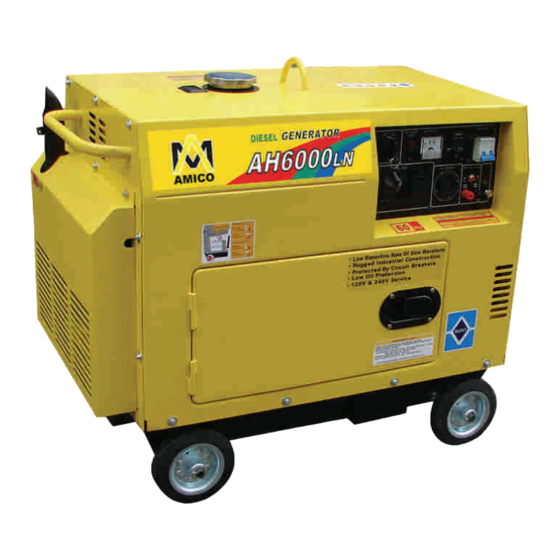
1. MAIN TECHNICAL SPECIFICATIONS AND DATA Model AH6000LN Item Rated frequency (Hz) Rated power (kVA) Rated voltage (AC)(V) 120/240 Rated current (AC)(V) 50/25 3600 Rated revolution speed(r/min) Power factor (cos ) Controlled silicon self excitation Excitation mode constant voltage DC output 12V/8.3A... -
Page 7: Cofiguration
2.CONFIGURATION 2.1 Parts name AC output DC output Engine starter switch Fuelfiller cap Lifting eye Low oil pressureg lamp Exhaust Outlet fo cooling air... -
Page 8: Preparation For Starting
2.2 Control panel AH6000LN 3. PREPARATION FOR STARTING 3.1 Selection and handling of the fuel oil Selection of fuel oil Only use the light diesel, which is most suitable for the engine, Keep dust and water out of the fuel When filling the fuel tank from drums, make sure that no dust or water is mixed in the fuel. - Page 9 WARNING AMICO series generating set are equipped with Iow oil warning system This system will stops the engine automatically when the oil level falls below the lower level. This prevents accidents such as bearing seizures, etc.
- Page 10 2. Reattach the air cleaner cover and screw on the wing nut. Elelment 3.4 Check the generating set 1. Turn off the main switch and any other Low oil warning lamp loads. WARNING Be sure to turn offthe main switch before AC output receptacle starting.
- Page 11 "OFF", the sudden application of load when the engine is started could be very dangerous. 3-5 How to open the cabinet door and covers of AMICO LN series generating set 1. Open the cabinet door for daily inspection.
-
Page 12: Start The Generating Set
Avoid applying any heavy loads during the break-in pedod AMICO recommends to run the engine at 3600 r/min with 50% load in break-in period. Replace the engine oil on time. Replace the engine oil while the engine is warm after 20-hours -running. the old engine oil will be drained out completely. - Page 13 1. Starting Open the fuel cock. Set the engine speed lever at "RUN" Engine speed lever position. Engine speed aver Photo shows RUN position Photo shows RUN position Engine starter key Turn the starting key clockwise to "START" position. Remove your hand from the key as soon as the engine starts.
-
Page 14: Operate The Generating Set
2. Battery 1.when you install it,frist check batteryís polarity if it is same with generatorís anode &cathode line,check volt if it is 12.3V,otherwise must electricize, 2.every month check volt if it is right,free charge maintenance batteryís charge,volt is 13.5V-14.5v 3.check electric systerm if it have creepage,otherwise damage battery, 4.if batteryís volt is not enough,electrica energy is low,please remove of battery and electricize, on time,only have 5-6hours is ok,... -
Page 15: Load
3. Check the color of the exhaust. (Is it black or too white?) If you notice any of the above-mentioned phenomenon happened, stop the eh- gine and find out the fault cause or contact with AMICO agent. CAUTION If the engine has been running, the muffler will be very hot, Be careful not to touch the muffler. - Page 16 6.1 AC application 1. Be sure to run the generating set at rated speed, otherwise capacitor will produce the forced excitation. If the running is for a long time under such condition. capacitor will be burned out, 2. After switching on the air switch, observe the voltmeter on the panel of the control cabinet, the voltmeter should point to 120V 5%(60Hz) for single-phase gener ating set;...
- Page 17 CAUTION Connect the positive and negative poles of the battery with the positive and negative poles of DC terminals separately. Do not confuse them, otherwise the battery and generating set will burn out Do not connect the positive pole of the battery with its negative pole, other- wise the battery damage will result, Do not connect the positive pole of the DC terminal with its negative pole.
- Page 18 6.3 Electrical appliance particularly motor-driven equipment will produce very high current while starting, the below table provides the reference for connecting these apparatus to the generator set. EXAMPLE WATTAGE TYPICAL TYPE APPLIANCE STARTING RATED STARTING RATED APPLIANCE Incande- scent Incandescent Incandescent I00VA I00VA...
-
Page 19: Stop The Generating Set
7.STOP THE GENERATING SET 1. Disconnect the load from the generating set. 2. Turn off the breaker of the generating set. 3. Set the speed lever at "RUN" position, run the generating set without load for about 3 minutes. Do not stop the engine suddenly, otherwise the temperature will increase abnormally, the nozzle will blocked and the generating set will be damaged... - Page 20 Grind intake/exhaust valves Replace piston ring Every month Check battery electrolyte Check carbon brush and slip ring Check insulation resistance The generating set has been stored more than lOdays Note:" " indicates that special tools are required, please contact with AMICO agent.
- Page 21 8.1 Replace engine oil Remove the oil filler cap. Remove the drain plug and drain the old oil while the engine is still warm. The plug is located on the bottom of the cylinder block. Tighten the drain plug and refill with the recommended oil. Oil fillercap/Dipstick Drain plug 8.2 Clean the engine oil filter...
- Page 22 2. Grind the intake/exhaust valves. 3 Replace the piston ring. All these operation require special tools and skills, contact with your AMICO agent. WARNING Do not perform the injection nozzle test near an open fire or any other kind of fire.
-
Page 23: Long-Term Storage
8.7 Check the battery and charge the battery 1.when you install it,frist check batteryís polarity if it is same with generatorís anode &cathode line,check volt if it is 12.3V,otherwise must electricize, 2.every month check volt if it is right,free charge maintenance batteryís charge,volt is 13.5V-14.5v 3.check electric systerm if it have creepage,otherwise damage battery,... -
Page 24: Troubleshooting And Remedy
3. Remove the screw plug on the cylinder head cover and refill 2cc engine oil, then put the plug in place, 4. Turn the engine 2~3 seconds with the decompression lever set at the non-com- pression position, and the starting key at the "START" position.( (Do not start the engine.) 5. -
Page 25: Detail Diagram
11.DETAIL DIAGRAM... - Page 27 Quantity Part Description Number Part Number Silencer Cover AH6000LN001 Silencer Bend AH6000LN002 Left Board AH6000LN003 Back Door AH6000LN004 Fixing Sleeve For Observing Bore AH6000LN005 Fixing Sleeve For Input Of Fule Tank AH6000LN006 Main Cover AH6000LN007 Swich AH6000LN008 Air Filter Baffle AH6000LN009 Accelerator Electomagnet AH6000LN010...
- Page 28 Quantity Part Number Number Part Description Pressingplate Of Accumulator AH6000LN046 AH6000LN047 Pulling Wire For Throttle AH6000LN048 Pulling Wire For Turn-off Alternator AH6000LN049 AH6000LN050 Output Wind Leading Shaft AH6000LN051 Manostat AH6000LN052 Gasket Of Output Bore Cf Series Disel Engine AH6000LN053 AH6000LN054 Pulling Role For Accelerator AH6000LN055 Intake Wind Leading Shaft...
-
Page 29: Panel Detail Diagram
12.PANEL DETAIL DIAGRAM... - Page 30 Quantity Part Number Number Part Description Panel AH6000LN073 M6X12 Bolt AH6000LN074 Starter Switch AH6000LN075 M4X30 Bolt AH6000LN076 3 Prong Socket AH6000LN077 M4X15 Bolt AH6000LN078 M5X25 Bolt AH6000LN079 Positive DC Port AH6000LN080 Negative DC Port AH6000LN081 Grounded Bolt AH6000LN082 Integrating AH6000LN083 DC Fuse AH6000LN084 Breaker...
-
Page 31: Wiring Diagram
13.WIRING DIAGRAM... -
Page 32: Limited Warranty
Starting batteries are not warranted by AMICO. All transportation cost under warranty including return to the factory if necessary, are to be prepaid by the purchaser. All decisions of AMICO with regard to this limited warranty shall be final. -
Page 33: Product Registrationcard
PRODUCT REGISTRATION CARD For more efficient customer service, please fill out the information below and mail to our produce Warranty and Registration Division: Amico International Corp. 4825 Gregg Road, Pico Rivera, CA 90660, U.S.A Tel: 562-908-0088 Fax: 562-908-1899 Website: www.amicousa.com Purchase Date. - Page 34 Address of user Place of purchase Packaging conditions Operating conditions Parts Conditions Malfunction problem Opinions or suggestions Note: Please mail the above card to: Amico International Corp. 4825 Gregg Road, Pico Rivera, CA 90660, U.S.A Tel: 562-908-0088 Fax: 562-908-1899 Website: www.amicousa.com...
- Page 35 Appendix: 1. Attached list of tools, fittings, and subassemblies Order No. Name Remarks 4-Stroke Air-cooled Diesel Generator Set Plastic cover Plug and power supply 2. Attached technical documents Order No. Name Remarks Air cooled diesel generator manual Diesel engine instruction manual Diesel engine parts listing Certificate of Quality Packing List...
Need help?
Do you have a question about the AH6000LN and is the answer not in the manual?
Questions and answers