
Related Manuals for TOWA AX-100


Summary of Contents for TOWA AX-100
- Page 1 Service Manual AX-100 (Black) TOWA Business Precision Electronics (Zhong Shan) CO., LTD. 2007-07 Table of contents...
-
Page 2: Table Of Contents
¢ ñ £ ® Product Specification ............................2 1£® General Specification ........................... 2 2£® Function Specification ..........................3 ¢ò £ ® Initialization ............................... 6 1£® Control lock and its function ........................6 2£® System clear ..............................6 3£® System reset ..............................6 ¢ó... -
Page 3: Product Specification
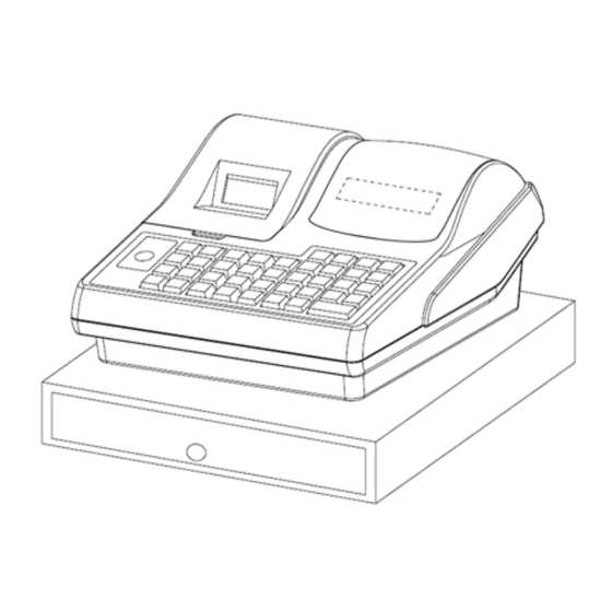
£ ® Product Specification 1¡ D General Specification 1¡¢ Front display 8 digits, 8-segments LED(Including decimal point) Your cash register has one 8-segments displays for the operator. It displays prices, subtotals, change due, status codes and so on. This display can show up to eight digits. 2¡¢... -
Page 4: Function Specification
2¡ D Function Specification 1¡¢ Support the setting of date¡¢ t ime¡¢ m achine number¡¢ r eceipt number¡¢ s etting password¡¢ t raining password¡¢ report number and so on 2¡¢ Department number 16 (there are 8 direct departments number£¬ by pressing the Department Shift Key the department number can be achieve 16) 1)Name 16 characters 2)Unit price Max can be set up to 8 digits (include decimal) when in sale can be manually... - Page 5 (include return and VOID)£¬ Non-add sale amount 7¡¢ LOGO Max 5 lines£¬ each line max 24 bytes 8¡¢ MESSAGE Max 5 lines£¬ each line max 24 bytes 9¡¢ Support main flag setting 10¡¢ Support keyboard setting 11¡¢ Support transaction name setting 12¡¢...
- Page 6 Z2£º Periodical reset report Non-sales count Half-height fonts print Clerk login and logout function Single-item sales function Multiplication function (number*price mode) Calculator function(addition¡¢ subtraction¡¢ multiplication¡¢ division) Department and PLU repeat entry function Barcode enter and look for PLU price (PLU number and Barcode number input) RA¡¢...
-
Page 7: Ò £ ® Initialization
£ ® Initialization 1£ ® Control lock and its function The control lock allows you to change the cash register mode. Your cash register has 5 different modes. Conversion mode is the mode in which you can insert manager key (MA) or operator key (OP) in the control lock and shift to any position you need to carry out operation. -
Page 8: Ó £ ® Module Connection Diagram
£ ® Module connection diagram £ ® Circuit instruction 1£ ® Power supply circuit This cash register power is supplied by transformer£¬ Input£º 220V AC or 240V AC ±10%/50Hz 0.15A£¬ Output£º AC11V/2A¡£ 1-1¡ ¢ +VCC£º As shown in Fig.1£ ¬ AC11V power supplied by transformer is input to mainboard through PN4 terminal£¬... - Page 9 output the steady DC+5V voltage which supplies for LED¡¢ COM¡¢ CPU¡¢ Flash and other logic chips. 1-4¡ ¢ +VHH£ºAs shown in Fig.2£ ¬ After the +VCC converted by DC/DC chip IC3 £¨ PQ1CG3032FZ£© £¬ it will output +VHH voltage which provides to the printer¡£ Fig.1 Fig.2 1-5¡...
-
Page 10: Reset And Power Failure Circuit
Vmm so as to preserve RAM and CPU data. The BT signal is connected to CPU I/O port for checking the voltage of the battery. Fig.3 2£ ® Reset and power failure circuit As shown in Fig.3£ ¬ after the machine power on,the IC4£¨ S-80846£© output high level£¬ After the high level signal pass through the transistor circuit, then the reset signals of the CPU(/RESET) come into being¡£... -
Page 11: Front Display Control And Keyboard Scan Circuit
As shown in Fig.5£ ¬ after power off£¬ W hen the IC4 £¨ S-80846£© i nput voltage below 4.7V£¬ V out output low level£¬ A t this time the PF signal comes into being£¬ C PU will execute power off process¡£ Fig.5 3£... - Page 12 As shown in Fig.7, this cash register keyboard is line- row scanning type keyboard, it adopts low electricity level signal to scan ( ) lines. Return signal by KS1-KS9 (KR1-KR5)lines retrace, C7¡¢ C5¡¢ ¡¢ C4¡¢ C3¡¢ C2¡¢ C1 are the lines used to scan P¡¢ R¡¢ X¡¢ Z lock signal, C6 is common signal back line by lock.
-
Page 13: Rear Display Control Circuit
4£ ® Rear display control circuit As shown in Fig.6, this cash register front display adopts 8 digits(DN1-DN2),8 segments LED, The rear display LED of voltage is provided by +2V-+2.2V¡£ G1-G8 are selection signals, sa-sg¡¢ dp are segment signals. 5£ ® Print circuit This cash register uses thermal printer£¬... -
Page 14: Communication Circuit
6£® Communication circuit As shown in Fig.10£ ¬ this cash register adopts RJ45 connection Port£¬ IC1£¨ MAX202SE£© is used to convert level between TTL/COMS and the RS232 £¬ thus achieve the COM communication. Fig.10... -
Page 15: Cpu£¨ Ic1£© Resource Allocation
7£ ® CPU¡ ] IC1¡ ^ Resource allocation PIN NAME DESCRIPTION PIN NAME DESCRIPTION Vpp/TEST LED_a LED_b LED_c LED_d /WAIT no use LED_e ASTB no use LED_f VDD1 RTP0 PRT_M.A TI5/TO5 RTP1 PRT_M.A\ TI6/TO6 RTP2 PRT_M.B TI7/TO7 RTP3 PRT_M.B\ TI8/TO8 RTP4 PRT_DST1 AS18... - Page 16 32.768KHz(OUT) no use 32.768KHz(IN) BUZZER /RESET RESET SI0/SDA0 PRT_LATCH INTP0 EU/JP PRT_DAT INTP1 PRT_PS SCL0/SCK0 PRT_SCKO INTP2/NMI POWER FAIL(PF) INTP3 no use INTP4 UPDATE KEY INTP5 UPDATE INTP6 F_/RESET AVDD AVREF0 ANI0 Input KR1 ANI1 Input KR2 ANI2 Input KR3 ANI3 Input KR4 ANI4...
-
Page 17: Ram£¨ Ic3
8£ ® RAM¡ ] IC3¡ ^ Function A0 to A18 Address Inputs I/O0 to I/O7 Date Inputs/Outputs Chip Select Output Enable Write Enable Ground Power Supply... -
Page 18: Õ £ ® Classify By Common Malfunctions And Dispose Of Method
£ ® Classify by common malfunctions and dispose of method ¡ ] 1¡ ^ Entire machine exceptionally Make sure the lock Is on the"P" position, then power on Entire machine does not have the response Please confirm the Input voltage Is OK or Not? voltage scope Replace the new fuse The fuse Is OK or Not? -
Page 19: Data Exceptionally
¡] 2¡ ^ Data exceptionally Notice£ º This cash register adopts standard 125V, 3.5A fuse¡£ Before replacing the fuse, please cut off the power supply£¬ the new fuse parameter must be as same as the machine required£¬ When assembly just twist the fuse properly to its position£¬ do not put with strong force£¬ in order to avoid damaging its internal structure. -
Page 20: Ö ¡ ¢ Pcb Layout Diagram£¨ Top Layer
¡ ¢ PCB layout diagram£ ¨ Top layer£ ©... -
Page 21: List Of Entire Machine
¡ ¢ List of entire machine... - Page 22 PARTS NAME NOTE DISPLAY UNIT FOR PZ-255 PZ-255 PCB DSP FR-1 1F 25*120 PCB1 UL2651-P AWM 4¡ Á 26AWG JPCABLE 16P 2.0 50L (TASC.SUS) LF P=2.0 LED YELLOW HLBW452G-A21 DN2 DN1 SIO BOARD UNIT FOR PZ-255 ¡ ð PZ-255 PCB S.I_O FR-1 1F 30*45 PCB1 CN3 CN4 CN1...
- Page 23 DN19 DN20 DN17 SBD 100MA/20V S 1608 MA2ZD14(PB FREE) RFGU TO-220 5V KA7805ETU RAM SOP32 1M KM681000CLG-7L(PBX) RESET SMT 4.6V TO-89 S-80846KNUA-D2C-T2G REGU T0220 3.5A PQ1CG3032FZ(PBFREE) DRV SOP14 LB1836 LB1836ML-TLM-E(PBFRE IC10 MASK CPU PZ-255 APL V£ ® UPD784214AGF SOP 74HC1G00 (1 GATE) 74HC1G00GW TR ARY NPN X8 500MA ULN2803L-S18-R IC12...
- Page 24 100K 1/10 SMT 1608 ERJ3GEYJ104V(PB FREE RN45 220 1/4 SMT 3216 RMC-18221JR(PB FREE) RN30 RN29 1M 1/10 SMT 1608 ERJ3GEYJ105V RN40 CHIP FUSE 3.5A SST3.5(PB FREE) 32.768KHZ OS-032768.KB BUZZER DIP KBS-13DB-4P-2 COIL 100UH DIP TC131M-4A-8026-B20 XTAL SMT 12.288MHZ SMD-49 12.288MHZ(PBX HEAT SINK DSP UNIT PZ-255 FOR PZ-255...
- Page 25 TOWA Business Precision Electronics (Zhong Shan) CO., LTD. Add£º Zhong Shan Torch High Tech Industrial Development Zone, GuangDong, China Tel£º £¨ 0760£© 3382308 Fax£º £¨ 0760£© 5318053...
Need help?
Do you have a question about the AX-100 and is the answer not in the manual?
Questions and answers
On our reports at the day end, there is often and amount with G beside it. What is this, and are the cashiers doing something wrong.