Table of Contents
Advertisement
Service
Manual
DISC PLAYER WITH AMPLIFIER
DEH-2237
VEHICLE
DESTINATION
Ranger
U.S.A., CANADA
- This service manual should be used together with the following manual(s):
Model No.
Order No.
CX-977
CRT2624
For details, refer to "Important symbols for good services".
PIONEER CORPORATION
PIONEER ELECTRONICS (USA) INC.
PIONEER EUROPE NV
Haven 1087 Keetberglaan 1, 9120 Melsele, Belgium
PIONEER ELECTRONICS ASIACENTRE PTE.LTD. 253 Alexandra Road, #04-01, Singapore 159936
C PIONEER CORPORATION 2003
FORD
DEH-2237ZF/X1R/UC
PRODUCED AFTER
August 2003
Mech. Module Remarks
S9
CD Mech. Module:Circuit Description, Mech.Description, Disassembly
4-1, Meguro 1-Chome, Meguro-ku, Tokyo 153-8654, Japan
P.O.Box 1760, Long Beach, CA 90801-1760 U.S.A.
ZF
X1R/UC
FORD PART No.
ID No. PIONEER MODEL No.
FS-4L5T-18C868-AE
K-ZZD. JUNE 2003 Printed in Japan
ORDER NO.
CRT3094
DEH-2237ZF/X1R/UC
Advertisement
Table of Contents

Subscribe to Our Youtube Channel
Related Manuals for Pioneer DEH-2237ZF X1R/UC


Summary of Contents for Pioneer DEH-2237ZF X1R/UC
- Page 1 PIONEER ELECTRONICS (USA) INC. P.O.Box 1760, Long Beach, CA 90801-1760 U.S.A. PIONEER EUROPE NV Haven 1087 Keetberglaan 1, 9120 Melsele, Belgium PIONEER ELECTRONICS ASIACENTRE PTE.LTD. 253 Alexandra Road, #04-01, Singapore 159936 C PIONEER CORPORATION 2003 K-ZZD. JUNE 2003 Printed in Japan...
-
Page 2: Safety Information
[ Important symbols for good services ] In this manual, the symbols shown-below indicate that adjustments, settings or cleaning should be made securely. When you find the procedures bearing any of the symbols, be sure to fulfill them: 1. Product safety You should conform to the regulations governing the product (safety, radio and noise, and other regulations), and should keep the safety during servicing by following the safety instructions described in this manual. -
Page 3: Table Of Contents
CONTENTS SAFETY INFORMATION ..............................2 1. SPECIFICATIONS .................................4 2. EXPLODED VIEWS AND PARTS LIST ..........................6 2.1 EXTERIOR ..................................6 2.2 CD MECHANISM MODULE ............................8 3. BLOCK DIAGRAM AND SCHEMATIC DIAGRAM......................10 3.1 BLOCK DIAGRAM .................................10 3.2 OVERALL CONNECTION DIAGRAM(GUIDE PAGE) ....................12 3.3 KEYBOARD UNIT ................................18 3.4 CD MECHANISM MODULE ............................20 4. -
Page 4: Specifications
1. SPECIFICATIONS General Power source ................14.4V DC(10.5V-16.0V allowable) Grounding system ..............Negative type Backup current ................3mA or less Dimensions .................188(W) x100(H) x187(D)mm Weight ..................2.0kg CD player System..................Compact disc audio system Usable discs ................Compact disc Signal format ................Sampling frequency : 44.1kHz Number of quantization bits: 16;linear S/N ....................70dB or more Distortion..................0.1% or less FM tuner... - Page 5 DEH-2237ZF/X1R/UC...
-
Page 6: Exploded Views And Parts List
2. EXPLODED VIEWS AND PARTS LIST 2.1 EXTERIOR DEH-2237ZF/X1R/UC... - Page 7 NOTE: - Parts marked by “*” are generally unavailable because they are not in our Master Spare Parts List. - Screws adjacent to ∇ mark on the product are used for disassembly. - For the applying amount of lubricants or glue, follow the instructions in this manual. ( In the case of no amount instructions, apply as you think it appropriate.) - EXTERIOR SECTION PARTS LIST Mark No.
-
Page 8: Cd Mechanism Module
2.2 CD MECHANISM MODULE GEM1040 GEM1035 GEM1035 DEH-2237ZF/X1R/UC... - Page 9 - CD MECHANISM MODULE SECTION PARTS LIST Mark No. Description Part No. Mark No. Description Part No. 1 CD Control Unit CWX2701 46 Gear CNV6320 2 Connector(CN701) CKS1959 47 Arm CNV6322 3 Connector(CN101) CKS3486 48 Arm CNV6323 4 Screw BMZ20P025FTC 49 Arm CNV6324 5 Screw...
-
Page 10: Block Diagram And Schematic Diagram
3. BLOCK DIAGRAM AND SCHEMATIC DIAGRAM 3.1 BLOCK DIAGRAM MOTHER UNIT FM/AM TUNER UNIT FM/AM 1ST IF 10.7MHz MPXREF 41kHz CN602 AMRF T51 Q51 CF51 CF52 CF53 AMDET AMANT ANTENNA L ch JACK IC 2 FM MPX R ch AMIN ANT ADJ COMP MIXER, IF AMP, DET. -
Page 11: Keyboard Unit
RESET IC 801 RESET S-80842CNDYI SYS+B REGULATOR VDD REGULATOR Q808 Q805 Q804 B.UP SYS+B B.UP Q873 DIAGNOSTICS Q807 IC 604 PDO,PDI,PCK BR9010FV-W epce,wc SWVDD Q874 Q806 Q691 SYSPW SYSPWR Q852 SYSPW syspwr SYSTEM CONTROLLER Q840 B SENSE SYS+B B.UP bsens IC 601(1/2) Q850 PD5756A... -
Page 12: Overall Connection Diagram(Guide Page)
3.2 OVERALL CONNECTION DIAGRAM(GUIDE PAGE) Note: When ordering service parts, be sure to refer to " EXPLODED VIEWS AND PARTS LIST" or "ELECTRICAL PARTS LIST". Large size SCH diagram FM/AM TUNER UNIT FM:-25.0dBs(100%,400Hz,MONO) AM:-25.0dBs(30% Mod.,400Hz,MONO) Guide page Detailed page FM:-35.47dBs AM:-35.47dBs CD: -1.97dBs ELECTRONIC VOLUME... - Page 13 MOTHER UNIT FM: +4.63dBs AM: +5.63dBs CD:+23.13dBs TRONIC VOLUME/ FM:-21.37dBs URCE SELECTOR AM:-20.37dBs CD: -2.87dBs OLLER NC(PTA) NC(PHONE INPUT +) NC(PHONE INPUT -) NC(PHONE SHIELD) NC(PTA) NOTE : NC(PHONE INPUT +) NC(PHONE INPUT -) Symbol indicates a resistor. Decimal points for resistor NC(PHONE SHIELD) No differentiation is made between chip resistors and and capacitor fixed values...
- Page 14 DEH-2237ZF/X1R/UC...
- Page 15 CD:+1.10dBs(1kHz,0dB) CN701 DEH-2237ZF/X1R/UC...
- Page 16 DEH-2237ZF/X1R/UC...
- Page 17 DEH-2237ZF/X1R/UC...
-
Page 18: Keyboard Unit
3.3 KEYBOARD UNIT (KL) (KL) 105mA, 8V CN604 DEH-2237ZF/X1R/UC... - Page 19 KEYBOARD UNIT VOLUME/POWER POWER CD EJECT SEEK DOWN SEEK UP TUNE DOWN TUNE UP MUTE DEH-2237ZF/X1R/UC...
-
Page 20: Cd Mechanism Module
3.4 CD MECHANISM MODULE PICKUP UNIT(SERVICE)(S9) RF AMP & MOTOR DRIVER LOGIC TABLE ACT/MOTOR DRIVER SPINDLE MOTOR M1 CXB6007 LOADING/CARRIAGE MOTOR M2 CXB5903 REGULATOR DEH-2237ZF/X1R/UC... - Page 21 CD CONTROL UNIT SERVO CONTROL/DSP/DAC/LPF & 16.934MHz CN607 SIGNAL LINE FOCUS SERVO LINE TRACKING SERVO LINE CARRIAGE SERVO LINE SPINDLE SERVO LINE SWITCHES: CONTROL UNIT S901 : HOME SWITCH..ON-OFF S902 : CLAMP SWITCH..ON-OFF S903 : DSCSNS SWITCH..ON-OFF S904 : 12EJ SWITCH..ON-OFF S905 : 8EJ SWITCH..ON-OFF The underlined indicates the switch position.
- Page 22 Note:1. The encircled numbers denote measuring pointes in the circuit diagram. 2. Reference voltage VREF:2.1V - Waveforms 5 CH1:FD 1 CH1:DSCSNS 5V/div. 1 CH1:DSCSNS 5V/div. 500mV/div. 6 CH2:FOK 2 CH2:CLCONT 2 CH2:CLCONT 5V/div. 5V/div. 5V/div. 500ms/div. 500ms/div. 500ms/div. 7 CH3:MD 3 CH3:LOEJ 3 CH3:LOEJ 5V/div.
- Page 23 % CH1:RFO 5 CH1:FD % CH1:RFO 1V/div. 1V/div. 1V/div. 200ms/div. 0 CH2:TE ^ CH2:FOP 0 CH2:TE 1V/div. 2V/div. 500mV/div. 500µs/div. 5ms/div. ! CH3:TD ! CH3:TD 1V/div. 1V/div. With no disk inserted During "Focus Close" 32 Track Jump 1 Track Jump Ref.
-
Page 24: Pcb Connection Diagram
4. PCB CONNECTION DIAGRAM 4.1 MOTHER UNIT NOTE FOR PCB DIAGRAMS MOTHER UNIT 1.The parts mounted on this PCB include all necessary parts for several destination. For further information for respective destinations, be sure to check with the schematic dia- gram. - Page 25 SIDE A ANTENNA FM/AM TUNER UNIT CN701 CN901 DEH-2237ZF/X1R/UC...
- Page 26 MOTHER UNIT DEH-2237ZF/X1R/UC...
- Page 27 SIDE B DEH-2237ZF/X1R/UC...
-
Page 28: Keyboard Unit
4.2 KEYBOARD UNIT KEYBOARD UNIT SIDE A LCD904 DEH-2237ZF/X1R/UC... - Page 29 KEYBOARD UNIT SIDE B CN604 DEH-2237ZF/X1R/UC...
-
Page 30: Cd Mechanism Module
4.3 CD MECHANISM MODULE CD CONTROL UNIT SIDE A 12EJ DSCSNS LOADING /CARRIAGE MOTOR SPINDLE MOTOR CN607 HOME PICKUP UNIT (SERVICE)(P9) VREF2 DEH-2237ZF/X1R/UC... - Page 31 CD CONTROL UNIT SIDE B CLAMP DEH-2237ZF/X1R/UC...
-
Page 32: Electrical Parts List
5. ELECTRICAL PARTS LIST NOTES: - Parts whose parts numbers are omitted are subject to being not supplied. - The part numbers shown below indicate chip components. Chip Resistor RS1/_S___J,RS1/__S___J Chip Capacitor (except for CQS..) CKS.., CCS.., CSZS..=====Circuit Symbol and No.===Part Name Part No. - Page 33 =====Circuit Symbol and No.===Part Name Part No. =====Circuit Symbol and No.===Part Name Part No. ------ ------------------------------------------ ------------------------- ------ ------------------------------------------ ------------------------- RS1/16S103J RS1/16S472J RS1/16S103J RS1/16S473J RS1/16S103J RS1/16S681J RS1/16S103J RS1/16S473J RS1/16S103J RS1/16S473J RS1/16S103J RS1/16S473J RS1/16S103J RS1/16S681J RAB4C682J RS1/16S681J RAB4C821J RS1/16S103J RS1/16S0R0J RS1/16S393J RS1/16S0R0J RS1/16S563J RS1/16S0R0J...
- Page 34 =====Circuit Symbol and No.===Part Name Part No. =====Circuit Symbol and No.===Part Name Part No. ------ ------------------------------------------ ------------------------- ------ ------------------------------------------ ------------------------- RS1/16S272J CKSRYB272K50 RS1/16S272J CKSRYB272K50 RD1/4PU0R0J CKSRYB104K16 RD1/4PU102J CKSRYB104K16 RS1/16S472J CEJQ330M10 RD1/4PU331J CEJQ010M50 RS1/16S272J CFTLA105J50 RS1/16S103J CEJQ100M16 RS1/16S332J CKSRYF104Z25 RS1/16S132J CFTNA224J50 RD1/4PU271J CFTNA224J50 RS1/16S471J...
- Page 35 =====Circuit Symbol and No.===Part Name Part No. =====Circuit Symbol and No.===Part Name Part No. ------ ------------------------------------------ ------------------------- ------ ------------------------------------------ ------------------------- CKSRYB681K50 Chip LED SML010PT(KL) CKSRYB681K50 Chip LED SML010PT(KL) CKSRYB104K25 SML-310PT(KL) CKSRYB102K50 SML-310PT(KL) CKSRYB473K50 SML-310PT(KL) CEJQ101M10 SML-310PT(KL) CEJQ100M16 SML-310PT(KL) CEJQ100M16 SML-310PT(KL) CEJQ101M16 Diode DAN202U(KL)
- Page 36 =====Circuit Symbol and No.===Part Name Part No. =====Circuit Symbol and No.===Part Name Part No. ------ ------------------------------------------ ------------------------- ------ ------------------------------------------ ------------------------- CAPACITORS RS1/16S331J RS1/16S332J RS1/16S684J CKSRYB104K16 RS1/16S103J CCSRCH681J50 RS1/16S103J CKSRYB104K16 CKSRYB104K16 RS1/16S183J CKSRYB104K25 RS1/16S123J RS1/16S622J Unit Number : CWX2701 RS1/16S622J Unit Name : CD Control Unit RS1/16S113J MISCELLANEOUS...
- Page 37 =====Circuit Symbol and No.===Part Name Part No. ------ ------------------------------------------ ------------------------- CKSRYB103K50 CKSRYB221K50 CKSRYB221K50 CKSRYB153K25 CKSRYB103K50 CEV101M10 CKSRYB104K16 CKSRYB104K16 10µF/10V CCH1349 CEV101M10 CKSRYB224K16 Miscellaneous Parts List Pickup Unit(Service)(P9) CXX1481 Motor Unit(SPINDLE) CXB6007 Motor Unit(LOADING/CARRIAGE) CXB5903 DEH-2237ZF/X1R/UC...
-
Page 38: Adjustment
6. ADJUSTMENT 6.1 CD ADJUSTMENT 1) Precautions 2) Test Mode • This unit uses a single power supply (+5V) for the reg- This mode is used for adjusting the CD mechanism ulator. The signal reference potential, therefore, is module of the device. connected to VREF(approx. - Page 39 - Flow Chart [4]+[6]+Reset [KEY] Test Mode In Contents Display [CD] Source On [SCAN] RF AMP Power On Power On New Test Mode Gain switching (T. offset is adjusted) (T. offset is not adjusted) [SCAN] [SEEK UP] [SEEK DOWN] Tracking Servo Focus Close / Automatic adjustment value CRG+...
-
Page 40: Checking The Grating After Changing The Pickup Unit
6.2 CHECKING THE GRATING AFTER CHANGING THE PICKUP UNIT • Note : The grating angle of the PU unit cannot be adjusted after the PU unit is changed. The PU unit in the CD mecha- nism module is adjusted on the production line to match the CD mechanism module and is thus the best adjusted PU unit for the CD mechanism module. - Page 41 Ech → Xch 20mV/div, AC Grating waveform Fch → Ych 20mV/div, AC 0° 30° 45° 60° 75° 90° DEH-2237ZF/X1R/UC...
-
Page 42: Cd Test Mode
6.3 TEST MODE - Error Messages If a CD is not operative or stopped during operation due to an error, the error mode is turned on and cause(s) of the error is indicated with a corresponding number. This arrangement is intended at reducing nonsense calls from the users and also for facilitating trouble analysis and repair work in servicing. - Page 43 - New Test Mode S-CD plays the same way as before. If an error such as off focus, spindle unlocking, unreadable sub-code, or sound skipping occurs after setup, its cause and time occurred (in absolute time) are displayed. During setup, operational status of the control software is displayed. These displays and functions are prepared for enhancing aging in the servicing and efficiency of trouble analysis.
- Page 44 (4) Display of Operational Status during Setup Status No. Contents Protective action Focus search start Focus search timeout. Focus search 2 Focus search timeout. Focus search 3 Focus search timeout. Focus search 4 Focus search timeout. Focus search(Setup protection) Focus slips off. Focus search(Fast recovery) Focus slips off.
- Page 45 (5) Display Examples 1) During Setup 8-digit display, 6-digit display 4-digit display(Auto setting) 4-digit display(Manual setting) TNO. Min Sec TNO. Min Sec 11 11' 11" 11' 11" 2) During Operation (TOC read, TRK search, Play, FF and REV) The same as in the normal mode. 3) When a Protection Error Occurred (A) Error display ((A)←→(B), (C) : SCAN key) 8-digit display...
-
Page 46: General Information
7. GENERAL INFORMATION 7.1 DIAGNOSIS 7.1.1 DISASSEMBLY Removing the Case (not shown) 1. Remove the Case. Removing the CD Mechanism Module (Fig.1) CD Mechanism Module Remove the four screws. Disconnect the connector and then remove the CD Mechanism Module. Removing the Grille Assy (Fig.1) Remove the two screws and then remove the Grille Assy. - Page 47 Removing the Chassis (Fig.3) Remove the four screws and then remove the Chassis. Chassis Fig.3 Removing the Holder (Fig.4) Remove the four screws and then remove the Holder. Holder Fig.4 DEH-2237ZF/X1R/UC...
- Page 48 Removing the Mother Unit (Fig.5) Remove the screw. Remove the two screws. Straighten the tabs at two locations indicated. Remove the two screws and then remove the Mother Unit. Mother Unit Fig.5 DEH-2237ZF/X1R/UC...
- Page 49 - How to hold the Mechanism Unit 1. Hold the top and bottom frame. 2. Do not squeeze top frame's front portion too tight, because it is fragile. Do not squeeze. - How to remove the Top and Bottom Frame 1.
- Page 50 - How to remove the CD Control Unit 1. Give jumper-solder treatment to the Flexible Wire of Jumper-Solder the Pickup unit, then remove the wire from the Connector. CD Control Unit 2. Remove all 4 points of solder-treatment on the Lead Wire.
-
Page 51: Connector Function Description
7.1.2 CONNECTOR FUNCTION DESCRIPTION FM/AM ANTENNA ANTENNA IN CASE RF GND POWER SUPPLY,SPEAKER PHONE NC(PTA) ILL+ NC(PHONE INPUT +) ILL- NC(PHONE INPUT -) START NC(PHONE SHIELD) CLOCK B.UP RUN/ACC RADIO GND POWER AMP GND DEH-2237ZF/X1R/UC... -
Page 52: Parts
7.2 PARTS 7.2.1 IC - Pin Functions (PD5756A) Pin No. Pin Name Format Function and Operation Tuner : PLL data output Tuner : PLL serial clock output BLPWR LCD back light power output ILMOUT Illumination D/A output LCDDT LCD driver : Data output PWMIN Illumination PWM input LCDCLK... - Page 53 Pin No. Pin Name Format Function and Operation Diagnosis EEPROM : Write control output AUXCNT0 Aux input selector 1 output Not used syspwr System power output FMUTE Front mute output ASYSON ACP-BUS : ACP power output wakeup Wake up key sense input ptain PTA interrupt input ACPINT...
- Page 54 * S-80842CNDYI * BR9010FV-W : Chip select input : Serial data clock input : Serial data input : Serial data output : Write control input :READY/busy status signal output - Pin Functions (LC75813E) Pin No. Pin Name Function and Operation Clock input Data input 3-89...
- Page 55 - FM/AM Tuner Unit FM/AM 1ST IF 10.7MHz MPXREF 41kHz AMRF T51 Q51 CF51 CF52 CF53 AMDET AMANT L ch IC 2 FM MPX R ch AMIN ANT ADJ COMP MIXER, IF AMP, DET. LDET FMANT RFGND FMRF CF202 IC 3 AM 2ND IF X901 IMG ADJ...
-
Page 56: Display
7.2.2 DISPLAY - LCD(CAW1822) DEH-2237ZF/X1R/UC... -
Page 57: Operational Flow Chart
7.3 OPERATIONAL FLOW CHART Power ON VCC=5V Pin 16,62 bsens Pin 27 bsens=L asens Pin 21 asens=L Load Micro ROM data SWVDD Pin 44 syspwr Pin 70 Source Keys Operative Source ON Completes power-on operation. (After that, proceed to each source operation) DEH-2237ZF/X1R/UC... -
Page 58: Cleaning
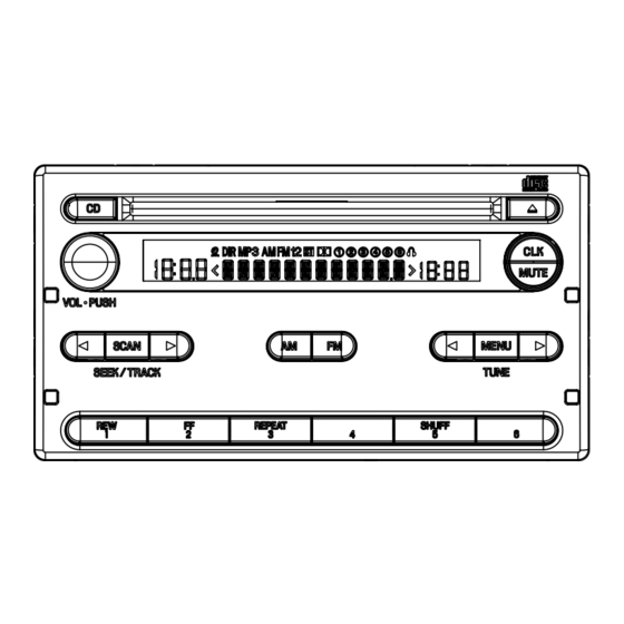
7.4 CLEANING Before shipping out the product, be sure to clean the following portions by using the prescribed cleaning tools: Portions to be cleaned Cleaning tools CD pickup lenses Cleaning liquid : GEM1004 Cleaning paper : GED-008 8. OPERATIONS DEH-2237ZF/X1R/UC... - Page 59 - RADIO VOLUME POWER ON/OFF SEEK TUNING UP/DOWN AUTOMATIC PRESET MEMORY MANUAL TUNING UP/DOWN PRESET CHANNEL RECALL PRESET CHANNEL MEMORY - CD VOLUME POWER ON/OFF TRACK SEARCH UP/DOWN CD EJECT REPEAT REVERSE FAST RANDOM SCAN FORWARD PLAY DEH-2237ZF/X1R/UC...
- Page 60 - AUDIO VOLUME POWER ON/OFF AUDIO MODE SELECT BALANCE FADER TREBLE BASS CLOCK ADJUSTMENT MUTE CLOCK ADJUSTMENT, AUDIO MODE UP/DOWN DEH-2237ZF/X1R/UC...
Need help?
Do you have a question about the DEH-2237ZF X1R/UC and is the answer not in the manual?
Questions and answers