Table of Contents
Advertisement
Quick Links
Advertisement
Table of Contents

Related Manuals for Falcon Generic 110 Ceramic


Summary of Contents for Falcon Generic 110 Ceramic
- Page 1 USER GUIDE & INSTALLATION INSTRUCTIONS 110 Ceramic...
- Page 2 SLOW BAKED LEG OF LAMB METHOD 1. Preheat the oven to 220 ¡C (for a conventional oven), 200 ¡C (for a fan oven) or gas mark 7. 2. Pull the small sprigs off the rosemary branches and set aside with the garlic. 2.
-
Page 3: Table Of Contents
Circuit Diagram: Hob (Classic Deluxe and Elan) Cooking Table Circuit Diagram: Conventional Oven Cleaning Your Cooker Circuit Diagram: Multi-function Oven (Elan) Circuit Diagram: Multi-function Oven Grills (Classic Deluxe) Control Panel and Doors Technical Data Cleaning Table Troubleshooting Generic 110 Ceramic U110039-03... -
Page 5: Before You Start
1. Before You Start... This User Guide covers a number of di erent models. Personal Safety Although some of the illustrations will look di erent to DO NOT modify this appliance. your particular model the functions will be the same. We This appliance is not intended for use by persons hope the meaning is clear. -
Page 6: Hob Care
Never leave the hotplate unattended at high heat settings. Fig.1-1 Pans boiling over can cause smoking, and greasy spills may catch on re. Use a deep fat thermometer whenever possible to prevent fat overheating beyond the smoking point. Never leave a chip pan unattended. Always heat fat slowly, and watch as it heats. -
Page 7: Cooker Care
Always LIFT pans o the hob. Sliding pans may cause marks Fig.1-4 and scratches (Fig.1-4). Always turn the control to the OFF position before removing a pan. Objects such as pan lids and items with thin bases including kettles, may stick to the ceramic surface. In the unlikely event that this happens DO NOT attempt to lift or lever the item to remove, as this may cause damage to both the item and the ceramic... -
Page 8: Cooker Overview
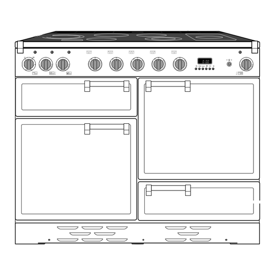
2. Cooker Overview DocNo.020-0002 - Overview - 90 Ceramic - Generic Fig.2-1 ºC ºC ArtNo.190-0001 - 110 Ceramic annotated GENERIC The 110 ceramic cooker (Fig.2-1) has the following features: Fig.2-2 A ceramic hob A control panel A separate grill or glide-out grill (depending on model) A conventional zoned oven or fan oven (depending on model) A fan oven... - Page 9 Make sure that the base of the pan is clean and dry to prevent Fig.2-5 any residue burning onto the hob panel. This also helps prevent scratches and deposits. Always use pans that are the same size as (or slightly larger than) the areas marked on the hob top (Fig.2-4).
-
Page 10: The Grill / Glide-Out Grill
The Grill / Glide-out Grill Fig.2-10 CAUTION: This appliance is for cooking purposes only. It must not be used for other purposes, for example room heating. ArtNo.330-0003 - Grill pan w handle pulled forwards CAUTION: Accessible parts may be hot when the grill is in use. -
Page 11: The Ovens
The Ovens Fig.2-14 The clock must be set to the time of day before the ovens will work. See the following section on ‘The Clock’ for instructions on setting the time of day. References to ‘left-hand’ and ‘right-hand’ ovens apply as viewed from the front of the appliance. - Page 12 The 6-button Clock Fig.2-15 Setting the Time of Day The 6-button LCD clock is shown in Fig.2-15. When the clock is rst connected the display ashes ( 0.00 ) and ( alternately. ArtNo.302-0002 - 6BC annotated Press and hold both the [C] and [D] buttons down (Fig.2-16).
- Page 13 AUTO is showing, you want to reset to manual cooking Fig.2-25 Fig.2-26 To return to manual cooking from any automatic setting, the ‘cook period’ must be cancelled. Press and hold the [E] button and then press the [ –] button until the display reads ( 0.00 ).
-
Page 14: Accessories
Accessories Fig.2-30 Oven Shelves Flat shelf Shelf guard In addition to the at shelves, some models are supplied with a drop shelf (Fig.2-30). The drop shelf increases the possibilities for oven shelf spacing. Front The oven shelves can be easily removed and re tted. Pull the shelf forward until the back of the shelf is stopped by Shelf guard the shelf stop bumps in the oven sides (Fig.2-31). -
Page 15: Main Oven Light
Main Oven Light Fig.2-37 Press the button to turn the light on (Fig.2-37). If the oven light fails, turn o the power supply before ArtNo.320-0017 Main oven light changing the bulb. See the ‘Troubleshooting’ section for details on how to change the bulb. Storage The bottom drawer is for storing oven trays and other Fig.2-38... -
Page 16: Cooking Tips
3. Cooking Tips Tips on Cooking with the Timer General Oven Tips If you want to cook more than one dish, choose dishes that The wire shelves should always be pushed rmly to the back require approximately the same cooking time. However, of the oven. -
Page 17: Cooking Table
4. Cooking Table DocNo.031-0004 - Cooking table - electric & fan single cavity The oven control settings and cooking times given in the table below are intended to be used Top (T) AS A GUIDE ONLY. Individual tastes may require the temperature to be altered to provide a preferred result. -
Page 18: Cleaning Your Cooker
5. Cleaning Your Cooker DocNo.040-0004 - Cleaning - 110 ceramic GENERIC Isolate the electricity supply before carrying out any major Fig.5-1 cleaning. Then allow the cooker to cool. NEVER use paint solvents, washing soda, caustic cleaners, biological powders, bleach, chlorine based bleach cleaners, coarse abrasives or salt. -
Page 19: Grills
Grills Fig.5-2 The grill pan and trivet should be washed in hot soapy water. After grilling meats or any foods that soil, leave to soak for a few minutes immediately after use. Stubborn particles may be removed from the trivet using a nylon brush. Alternatively, the grill pan can be washed in a dishwasher. - Page 20 Glass Fronted Door Panels (some models) Fig.5-7 The oven door front panels can be taken o so that the glass panels can be cleaned. Move the cooker forward to gain access to the sides (see the ‘Moving the Cooker’ section under ‘Installation’).
-
Page 21: Cleaning Table
Cleaning Table Cleaners listed (Table 5-1) are available from supermarkets or electrical retailers as stated. For enamelled surfaces use a cleaner that is approved for use on vitreous enamel. Regular cleaning is recommended. For easier cleaning, wipe up any spillages immediately. Hotplate Part Finish... -
Page 22: Troubleshooting
6. Troubleshooting Interference with and repairs to the hob MUST NOT Food is cooking too slowly, too quickly, or burning be carried out by unquali ed persons. Do not try Cooking times may di er from your previous to repair the hob as this may result in injury and oven. - Page 23 The oven light is not working Fig.6-1 The bulb has probably blown. You can buy a replacement bulb (which is not covered under the guarantee) from most electrical stores. Ask for an Edison ArtNo.324-0005 Oven light bulb screw tting 15 W 230 V lamp, FOR OVENS (Fig.6-1). It must be a special bulb, heat resistant to 300 °C.
-
Page 24: Installation
INSTALLATION Check the appliance is electrically safe when you have nished. 7. Installation You will need the following equipment to complete the Dear Installer cooker installation satisfactorily: Before you start your installation, please complete the details • Multimeter (for electrical checks). below, so that, if your customer has a problem relating to your installation, they will be able to contact you easily. -
Page 25: Positioning The Cooker
INSTALLATION Check the appliance is electrically safe when you have nished. Positioning the Cooker ArtNo.090-0028 - 90 cooker min spacing GENERIC Fig.7-1 Fig.7-1 and Fig.7-2 shows the minimum recommended 75 mm 75 mm distance from the cooker to nearby surfaces. 650 mm The cooker should not be placed on a base. -
Page 26: Repositioning The Cooker Following Connection
INSTALLATION Check the appliance is electrically safe when you have nished. Lowering the Two Rear Rollers Fig.7-5 To adjust the height of the rear of the cooker, rst t a 13 mm spanner or socket wrench onto the hexagonal adjusting nut (Fig.7-5). -
Page 27: Electrical Connection
INSTALLATION Check the appliance is electrically safe when you have nished. Electrical Connection Fig.7-8 This appliance must be installed by a suitably quali ed electrician to comply with the relevant electrical regulations, and also the local electricity supply company requirements. Current Operated Earth Leakage Breakers The combined use of your induction cooker and other domestic appliances may cause nuisance tripping, so we... -
Page 28: Final Fitting
INSTALLATION Check the appliance is electrically safe when you have nished. Final Fitting Fig.7-10 Fitting the Handles and Handrail (depending on model) Remove the 4 mm Allen screws from the doors (Fig.7-10). Fit the door handles and secure using the 4 mm screws. ArtNo.215-0026 - Handle gaskets fixed The handles should be above the xings. -
Page 29: Circuit Diagrams
8. Circuit Diagrams ArtNo.095-0003 - Circuit diagram - 90 induction Circuit Diagram: Hob (with warmer plate) To cooling fan 1.65kW 1.1kW 2.02kW 1.1kW 1.56kW bk/w ArtNo.082-0023 - 110 Ceramic (hob warmer only) - circuit diagram Connections shown in the circuit diagram are for single -phase. Ratings are for 230 V 50 Hz. Code Description Code Colour Blue... -
Page 30: Circuit Diagram: Hob (Classic Deluxe And Elan)
Circuit Diagram: Hob (Dual purpose hob/warmer plate) To cooling fan P5 P6 P7 P8 5 6 7 8 1.65kW 1.1kW 2.02kW 1.1kW 1.1kW 1.56kW bk/w ArtNo.082-0024 - 110 Ceramic (hob) - circuit diagram Connections shown in the circuit diagram are for single-phase. The ratings are for 230 V 50 Hz. Code Description Code Colour Left-hand end dual circuit hob energy regulator... - Page 31 Circuit Diagram: Hob (Classic Deluxe and Elan) To cooling fan P5 P6 P7 P8 5 6 7 8 1.65kW 1.1kW 2.02kW 1.1kW 1.1kW 1.56kW bk/w ArtNo.082-0020 - 110 Ceramic (hob) - Classic DL circuit diagram Connections shown in the circuit diagram are for single-phase. The ratings are for 230 V 50 Hz. Code Description Code Colour Left-hand end dual circuit hob energy regulator...
-
Page 32: Circuit Diagram: Conventional Oven
Circuit Diagram: Conventional Oven To terminal 2 on the warmer hob controller switch br br ArtNo.082-0025 - 110 Ceramic (oven) - Circuit diagram The connections shown in the circuit diagram are for single-phase. The ratings are for 230 V 50 Hz. Code Description Code Description Code Colour... -
Page 33: (Elan)
Circuit Diagram: Multi-function Oven (Elan) To terminal P6 on the warmer hob controller switch br v P033458 P028728 P033458 The connections shown in the circuit diagram are for single- phase. The ratings are for 230 V 50 Hz. Code Description Code Description Code Colour Grill energy regulator... -
Page 34: (Classic Deluxe)
Circuit Diagram: Multi-function Oven (Classic Deluxe) To terminal P6 on the warmer hob controller switch P038434 P033458 P033458 br br br ArtNo.082-0021 - 110 ceramic (oven) - Classic DL circuit diagram The connections shown in the circuit diagram are for single-phase. The ratings are for 230 V 50 Hz. Code Description Code Description Code Colour... -
Page 35: Technical Data
9. Technical Data ArtNo.100-0002 - Technical data - 90 ceramic - GENERIC INSTALLER: Please leave these instructions with the user. DATA BADGE LOCATION: Cooker back, serial number repeater badge below oven door opening. COUNTRY OF DESTINATION: GB, IE. Connections Electric 230 / 400 V 50 Hz Dimensions Overall height... - Page 39 Gas Safe registered engineer for gas appliances or an approved electrician for electrical models. CONSUMER SERVICE LINES OPEN: For a competitive quote and to arrange for a Falcon approved Monday to Thursday 8amÐ6pm engineer to attend, call Consumer Services on: 0870 789 5107.
- Page 40 Registered in England and Wales. Registration No. 354715 Registered Office: Juno Drive, Leamington Spa, Warwickshire, CV31 Falcon continuously seeks improvements in specification, design and production of products and thus, alterations take place periodically. Whilst every effort is made to produce up-to-date literature, this booklet should not be regarded as an infallible...
Need help?
Do you have a question about the Generic 110 Ceramic and is the answer not in the manual?
Questions and answers