Advertisement
Table of Contents
- 1 Table of Contents
- 2 Description
- 3 Operation
- 4 Specifications
- 5 Installation
- 6 Installation Testing
- 7 Equipment and Accessory Part Numbers
- 8 Notes for Installation Figures
- 9 Figure 1 - Wiring Diagram
- 10 Figure 2 - Outline Drawing
- 11 Figure 3 - Code Programming
- 12 Figure 4 - 20 Db Attenuator
- 13 Figure 5 - Annunciator Output Circuits
- Download this manual
Advertisement
Table of Contents

Related Manuals for Avtech CSD-714 Selcal


Summary of Contents for Avtech CSD-714 Selcal
- Page 1 An Aviation Technologies Company Avtech Corporation 3400 Wallingford Ave. North Seattle, WA 98103-9041 www.avtcorp.com Tel (206) 695-8000 Fax (206) 695-8011 INSTALLATION MANUAL CSD-714 SELCAL DECODER...
- Page 2 File Last Saved: April 16, 2001 (3:20PM) CSD-714 SELCAL INSTALLATION AND OPERATION MANUAL Avtech Part Numbers 1200008-000, -001, -002, & -003 MANUAL PART NUMBER 0200013-000 PROPRIETARY RIGHTS NOTICE THIS DATA IS PROPRIETARY TO AVTECH CORP. DISCLOSURE, REPRODUCTION, OR USE OF THIS DATA FOR ANY PURPOSE IS NOT AUTHORIZED WITHOUT WRITTEN PERMISSION FROM AVTECH CORP.
- Page 3 REV PAGE DESCRIPTION APPROVED Cloned from Coltech document 0200013-000 Rev C. All textual references to Coltech and formatting has been changed to Avtech where possible. This component maintenance manual may contain references to Coltech drawings and document numbers. REF DCR D010021...
- Page 4 CSD-714 Installation and Operation Manual SERVICE BULLETIN RECORD Service Date Model Bulletin Issued Effected Subject 23-21-01 June 1995 Seattle, WA USA Rev 1 Page II...
- Page 5 CSD-714 Installation and Operation Manual LIST OF EFFECTIVE PAGES Section Page Date 23-21-01 June 1995 Seattle, WA USA Rev 1 Page III...
-
Page 6: Table Of Contents
CSD-714 Installation and Operation Manual TABLE OF CONTENTS TITLE PAGE DESCRIPTION ............. . 1 OPERATION . -
Page 7: Description
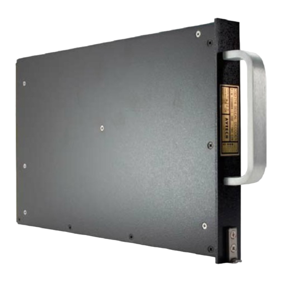
CSD-714 Installation and Operation Manual DESCRIPTION The CSD-714 SELCAL DECODER is a rack mounted, 16 tone decoder for the ICAO and ARINC standard SELCAL system, as defined in RTCA paper DO-93. It is available in both two channel (-001, -003) and five channel (-000, -002) versions. It has independent inputs for up to five radios, depending on version, to drive up to five decoder channels. -
Page 8: Operation
CSD-714 Installation and Operation Manual OPERATION Pilot operation of the CSD-714 is limited to resetting it after a call and performing a self-test. Normal Operation There are several installation options concerning how the annunciator lamps and audio annunciation work, as well as how the unit is reset after a call. The lamps may be connected to either be on steady or to flash when a call is received, and the audio annunciator may either ring once, ring repeatedly, or not at all. -
Page 9: Specifications
CSD-714 Installation and Operation Manual SPECIFICATIONS Model Number: CSD-714 Avtech Part Numbers: 1200008-000 (5 channel, standard self-test) 1200008-001 (2 channel, standard self-test) 1200008-002 (5 channel, auto-reset self-test) 1200008-003 (2 channel, auto-reset self-test) Certified to TSO: Conforms to RTCA Spec: DO-93 as amended. - Page 10 CSD-714 Installation and Operation Manual Mating Connector: ARINC 600 style, size 1 with blank cavity A, Middle insert Arrangement 01 (60 pins), Bottom insert Arrangement 03 (2 coax, 2 size 16 pins, 1 size 12 pin). Tone Inputs: Two or five inputs, transformer coupled. Each input is nominally 10,000 ohms input impedance.
-
Page 11: Installation
CSD-714. In this case, a 10 to 1 voltage divider (20 dB of attenuation) should be used in the audio input to the decoder. Avtech provides a in line attenuator under the part number 1200009-000 or one may be fabricated locally using Figure 4 as a guide. -
Page 12: Installation Testing
SELCAL decode should be received on all annunciators simultaneously. Using a ground test set such as the Avtech CTS-700 SELCAL/ATSCALL Ramp Test Set, select the frequency for test on one of the communication transceivers to which the CSD-714 is connected. -
Page 13: Notes For Installation Figures
CSD-714 Installation and Operation Manual NOTES FOR INSTALLATION FIGURES Note 1 - DECODE PROGRAMMING Programming the CSD-714 to respond to a selective call is done by connecting the code selection pins on the rear connector to the CODE SELECT RETURN pin on the rear connector (Pin MP9B). - Page 14 CSD-714 Installation and Operation Manual If manual reset is desired, they may all be tied together and grounded through a normally open, momentary contact switch. The SELF-TEST input (Pin MP3D) is activated by grounding it momentarily. All of these inputs are considered grounded when the voltage on the pin is less than 3.5 volts and are open when it is above 8 volts.
- Page 15 CSD-714 Installation and Operation Manual If the squelched audio output of the VHF is used, care must be taken to keep the audio input to the CSD-714 within rating. The frequency response of the output must be such that the difference in output level at any two frequencies between 300 and 1500 Hz is less than 3 dB.
-
Page 16: Figure 1 - Wiring Diagram
CSD-714 Installation and Operation Manual Figure 1 - Wiring Diagram 23-21-01 June 1995 Seattle, WA USA Rev 1 Page 10... -
Page 17: Figure 2 - Outline Drawing
CSD-714 Installation and Operation Manual Figure 2 - Outline Drawing 23-21-01 June 1995 Seattle, WA USA Rev 1 Page 11... -
Page 18: Figure 3 - Code Programming
CSD-714 Installation and Operation Manual Code Letter Position J1 Pin First MP10D MP10C MP10B MP10A Second MP11D MP11C MP11B MP11A Third MP13D MP13C MP13B MP13A Fourth MP15D MP15C MP15B MP15A Code Letter J1 MP10, MP11, MP13, MP15 Pin Coding DCBA DCBA 0001 1001... -
Page 19: Figure 4 - 20 Db Attenuator
CSD-714 Installation and Operation Manual Figure 4 - 20 dB Attenuator 23-21-01 June 1995 Seattle, WA USA Rev 1 Page 13... -
Page 20: Figure 5 - Annunciator Output Circuits
CSD-714 Installation and Operation Manual Figure 5 - Annunciator Output Circuits 23-21-01 June 1995 Seattle, WA USA Rev 1 Page 14...
Need help?
Do you have a question about the CSD-714 Selcal and is the answer not in the manual?
Questions and answers