Table of Contents
Advertisement
Quick Links
INSTRUCTIONS FOR FINAL ASSEMBLY
FOR YOUR INFORMATION
To make your modeling experience totally enjoyable, we recommend that you get experienced, knowledgeable help with
assembly and during your first flights. Your local hobby shop has information about flying clubs in your area whose
membership includes qualified instructors. If there is no hobby shop in your area, we recommend that you contact the
AMA at the address below. They will be able to help you locate a flying field near you.
The Modeltech P-51D .46 ARF is distributed exclusively by Global Hobby Distributors 18480 Bandilier Circle, Fountain Valley, CA 92728
All contents copyright © 2001, Global Hobby Distributors Version V1.0 September 2001
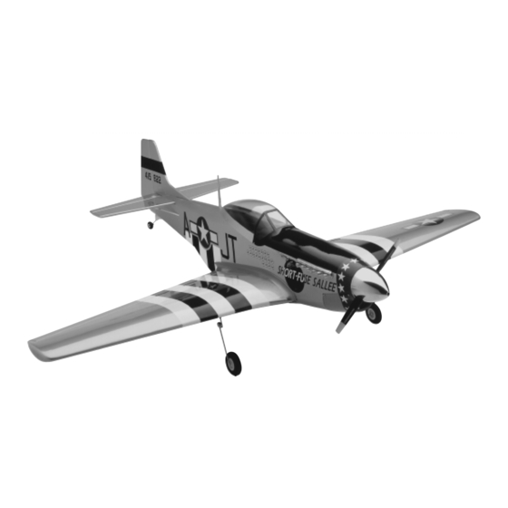
Specifications:
Wing Span: 57 inches
Wing Area: 612 square inches
Length: 51 inches
Weight: 5.8 - 6.2 Lbs. Ready-to-Fly
Power: .46 Two Stroke or .61 Four Stroke
Radio: 5 Channel w/4 Standard Servos & 1 Retract Servo
Academy of Model Aeronautics
5151 East Memorial Drive
Muncie IN 47302-9252
www.modelaircraft.org
See other exciting Modeltech ARF airplanes at http://modeltech.globalhobby.com
(800) 435-9262
1
Advertisement
Table of Contents

Subscribe to Our Youtube Channel
Related Manuals for Modeltech MUSTANG P-51D .46 ARF


Summary of Contents for Modeltech MUSTANG P-51D .46 ARF
-
Page 1: Specifications
(800) 435-9262 www.modelaircraft.org The Modeltech P-51D .46 ARF is distributed exclusively by Global Hobby Distributors 18480 Bandilier Circle, Fountain Valley, CA 92728 All contents copyright © 2001, Global Hobby Distributors Version V1.0 September 2001 See other exciting Modeltech ARF airplanes at http://modeltech.globalhobby.com... -
Page 2: Table Of Contents
TABLE OF CONTENTS Safety Warning ......................2 Introduction ....................... 3 Our Recommendations ....................4 Additional Items Required ..................5 Tools and Supplies Required ..................5 Metric Conversion Chart ................... 5 Kit Contents....................... 6 Replacement Parts ..................... 8 A Note About Covering .................... 8 Section 1: Assembling the Wing ............... -
Page 3: Introduction
"shelf paper" like some other manufacturers use. We hope you enjoy your new Modeltech P-51D .46 ARF as much as we have enjoyed designing and building it for you. If you have any questions or comments, please feel free to contact us. We have included a product survey in the back of this instruction manual. -
Page 4: Our Recommendations
OUR RECOMMENDATIONS This section describes our recommendations to help you in deciding which types of accessories to purchase for your new P-51D .46 ARF. These suggestions are not set in stone, but they should provide you with a good starting point. Two Stroke Engine with Fixed Landing Gear To get the P-51D flying as soon as possible, for the least amount of money, it can be assembled using a two stroke engine and the included fixed main landing gear. -
Page 5: Additional Items Required
2" 50.8mm 24" 609.6mm 1/16" 1.6mm 3/8" 9.5mm 3" 76.2mm 30" 762.0mm 3/32" 2.4mm 1/2" 12.7mm 6" 152.4mm 36" 914.4mm 1/8" 3.2mm 5/8" 15.9mm 12" 304.8mm 5/32" 4.0mm 3/4" 19.0mm 18" 457.2mm See other exciting Modeltech ARF airplanes at http://modeltech.globalhobby.com... -
Page 6: Kit Contents
KIT CONTENTS We have organized the parts as they come out of the box for easier identification during assembly. Before you begin assembly, group the parts like we list them below. This will ensure that you have all of the parts before you begin assembly and it will also help you become familiar with each part. - Page 7 {1} Decal Set {2} 4mm Nylon Spacers {2} 3mm x 5mm Machine Screws IMPORTANT Some of the parts listed in the Retract Landing Gear Assembly section are taken from the Fixed Landing Gear parts. See other exciting Modeltech ARF airplanes at http://modeltech.globalhobby.com...
-
Page 8: Replacement Parts
REPLACEMENT PARTS Global stocks a complete line of replacement parts for your Modeltech P-51D .46 ARF. Listed below are the replacement parts that are available along with their respective part numbers for easy ordering convenience. These replacement parts can be ordered through your local hobby dealer or directly from Global by calling 1-714-963-0329. -
Page 9: Section 1: Assembling The Wing
Use a ruler and a pencil to locate and draw a vertical centerline on each side of the plywood dihedral brace. See other exciting Modeltech ARF airplanes at http://modeltech.globalhobby.com... - Page 10 Test-fit the dihedral brace into each wing half. It should slide into each half up to the centerline you drew. If it does not fit properly, use 220 grit sandpaper to lightly sand the edges and tips of the brace. WARNING When installing the brace, make sure the top of the brace (it's straight, not angled) is toward the top of the wing.
-
Page 11: Section 2: Mounting The Wing
Promax Canopy Scissors 220 Grit Sandpaper w/Sanding Block Electric Drill Step 1: Aligning the Wing With the fuselage upside down, locate and draw a vertical centerline on the back of the wing saddle. See other exciting Modeltech ARF airplanes at http://modeltech.globalhobby.com... - Page 12 Measure 5/8" in front of the trailing edge of the wing and draw two marks, one on each side of the centerline. Measure 1-3/8" out from each side of the centerline and draw two intersecting marks. Place the wing into the wing saddle and push the trailing edge down firmly into place. Carefully align the centerline of the wing (the center joint) with the vertical centerline you drew on the fuselage.
- Page 13 Set the wing back into the wing saddle and realign it. Secure the wing into place using two 5mm x 30mm machine screws and two 5mm flat washers. Don't overtighten the screws. You don't want to crush the wing. See other exciting Modeltech ARF airplanes at http://modeltech.globalhobby.com...
- Page 14 Step 5: Installing the Leading Edge Fairing Using a pair of scissors, carefully cut out the molded plastic leading edge fairing around its outer edges. Leave about 1/8" of plastic around the front edge of the fairing to use as a gluing surface. Test fit the fairing onto the wing.
-
Page 15: Section 3: Mounting The Radiator Scoop
Before using epoxy to glue anything to plastic, use 220 grit sandpaper to lightly sand the gluing surface of the plastic. This will roughen up the smooth surface, resulting in a much better bonding area for the epoxy. See other exciting Modeltech ARF airplanes at http://modeltech.globalhobby.com... - Page 16 Test fit the plywood support brace to the front of the radiator back section. There should be a 1/16" space between the edge of the brace and the bottom of the scoop. The ends of the brace should be nearly flush with the sides of the scoop.
- Page 17 Using a pencil, mark the locations of the two wing bolts onto the bottom of the scoop. Using a 3/8" drill bit, drill two holes through the scoop at the locations you marked. See other exciting Modeltech ARF airplanes at http://modeltech.globalhobby.com...
-
Page 18: Section 4: Installing The Horizontal Stabilizer
Using a pair of scissors, cut out the back of the scoop to allow room for you to install and retrieve the wing bolts from the wing. Glue the radiator scoop into place using Kwik Bond 5 Minute Epoxy. Remove any excess epoxy using a paper towel and rubbing alcohol, and hold the scoop firmly in place until the epoxy sets up. - Page 19 If the stabilizer is out of alignment, remove it and use 220 grit sandpaper with a sanding block to sand down the higher side of the stabilizer mounting slot, then reinstall the stabilizer and check the alignment once more. Repeat this procedure until you are satisfied with the alignment. See other exciting Modeltech ARF airplanes at http://modeltech.globalhobby.com...
-
Page 20: Section 5: Installing The Vertical Stabilizer
Step 2: Mounting the Horizontal Stabilizer With the stabilizer properly aligned, use a pencil to draw a line on each side of the stabilizer where it meets the fuselage sides. Do this on both the top and bottom. Remove the stabilizer. Using a modeling knife, cut away and remove the covering from between the lines you drew. - Page 21 Push the stabilizer into place and realign it, double checking all of your measurements once more before the epoxy sets up. Quickly remove the excess epoxy and use pieces of masking tape to hold the stabilizer in place until the epoxy has fully cured. See other exciting Modeltech ARF airplanes at http://modeltech.globalhobby.com...
-
Page 22: Section 6: Hinging The Control Surfaces
SECTION 6: HINGING THE CONTROL SURFACES YOU'LL NEED THE FOLLOWING PARTS: {17} C/A Style Hinges (removed in previous steps) YOU'LL NEED THE FOLLOWING SUPPLIES: Kwik Bond Thin C/A Paper Towels Kwik Bond 5 Minute Epoxy Rubbing Alcohol Kwik Bond C/A Debonder NHP Epoxy Mixing Sticks Excel Modeling Knife NHP Epoxy Mixing Cups... -
Page 23: Section 7: Installing The Tail Wheel Assembly
Push one 2mm wheel collar into the molded recess in the nylon tail wheel tiller arm. Carefully rotate the wheel collar until the threaded hole in the collar lines up with the molded hole in the side of the tiller arm. See other exciting Modeltech ARF airplanes at http://modeltech.globalhobby.com... - Page 24 Partially thread one 2mm x 5mm machine screw through the tiller arm and into the wheel collar. Push the tail wheel wire up through the tail wheel bracket, then slide the tiller arm over the wire and push it down against the bracket.
-
Page 25: Section 8: Installing The Optional Fixed Main Gear
The center of each mount is located 9" out from the centerline of the wing. Each mount is 2-3/4" long and 1-9/16" wide. Do not remove the covering from over the precut wheel wells that are next to the gear mounts. See other exciting Modeltech ARF airplanes at http://modeltech.globalhobby.com... - Page 26 Test fit each precovered plywood landing gear mount onto the hardwood mounting rails in the wing. IMPORTANT Position the blocks so the predrilled hole in the groove is toward the centerline of the wing. When satisfied with the fit, glue the mounts into place using Kwik Bond 30 Minute Epoxy. Quickly remove any excess epoxy using a paper towel and rubbing alcohol.
- Page 27 Slide one 60mm wheel, recessed side toward the wing tip, onto each axle. Secure each wheel in place using one 4mm wheel collar and one 3mm x 5mm machine screw. Tighten the screws firmly. See other exciting Modeltech ARF airplanes at http://modeltech.globalhobby.com...
-
Page 28: Section 9: Installing The Optional Retract Landing Gear
SECTION 9: INSTALLING THE OPTIONAL RETRACT LANDING GEAR YOU'LL NEED THE FOLLOWING PARTS: {2} Retract Assemblies with Prebent Struts {2} 2mm x 230mm Pushrod Wires w/Z-Bends {2} 60mm Diameter Wheels {2} Adjustable Servo Connector Assemblies {2} Molded Plastic Wheel Cups {8} 3mm x 12mm Wood Screws {1} Plywood Retract Servo Tray (W-52) {2} 4mm Wheel Collars... - Page 29 The covered sides should face out toward you and the spacer-plates are cut to the same shape as the rails. When satisfied with the fit, glue the plates into place using Kwik Bond 5 Minute Epoxy. See other exciting Modeltech ARF airplanes at http://modeltech.globalhobby.com...
- Page 30 After the epoxy has cured, set one retract assembly into place. With the strut retracted, mark the portion of the wing that must be removed so the strut clears the wing when the strut is fully retracted. Note that the coil is toward the trailing edge of the wing. Remove the retract assembly.
- Page 31 When you bend the pushrod wires it will shorten each of them slightly. You may need to loosen the servo connectors and readjust the length of the pushrods so that the retracts will lock in both directions. See other exciting Modeltech ARF airplanes at http://modeltech.globalhobby.com...
- Page 32 Cycle the retracts up and down several times to test their operation. You may need to make small bends and/or adjustments to the pushrod wires and the servo connectors to eliminate any binding that might be present in the linkage. IMPORTANT It's important that the retract linkage operates smoothly.
- Page 33 Glue the wheel cup into place using Pacer Formula 560 Canopy Glue. Repeat the previous procedures to install the second wheel cup. See other exciting Modeltech ARF airplanes at http://modeltech.globalhobby.com...
-
Page 34: Section 10: Installing The Engine
SECTION 10: INSTALLING THE ENGINE YOU'LL NEED THE FOLLOWING PARTS: {1} Polished Chrome Spinner Assembly {4} 3mm Flat Washers {4} 3mm x 20mm Wood Screws YOU'LL NEED THE FOLLOWING SUPPLIES: # 1 Phillips Head Screwdriver 5/64" Drill Bit Adjustable Wrench Ernst Airplane Stand Electric Drill Pencil... -
Page 35: Section 11: Installing The Servos
Step 2: Installing the Fuselage Servos Install the rubber grommets and brass collets onto your elevator, rudder and throttle servos. Make sure to install the collets with the flanges toward the bottom of the servos. See other exciting Modeltech ARF airplanes at http://modeltech.globalhobby.com... - Page 36 Install the three servos into the servo tray taking note of the positions of the servo output shafts. To make it easier to install the servo mounting screws, drill 1/16" pilot holes through the servo tray. IMPORTANT Run the servo leads out toward the front of the airplane. Step 3: Installing the Aileron Servo Tray Center the aileron servo tray over the servo cutout in the wing.
-
Page 37: Section 12: Installing The Throttle Pushrod
Remove the throttle arm from your engine. Install the Z-Bend into the outermost hole in the throttle arm. See other exciting Modeltech ARF airplanes at http://modeltech.globalhobby.com... - Page 38 Slide the pushrod through the hole in the firewall and reinstall the throttle arm onto your engine. Step 2: Installing the Pushrod Connector Using wire cutters, remove all but one arm from a "4-point" servo horn. Install an adjustable servo connector into the fourth hole out from the center of the arm.
-
Page 39: Section 13: Installing The Elevator Pushrods
Using a ruler and a pencil, measure out 3/4" from the inside edge of each elevator half, at the hinge line, and draw a mark on each elevator half. IMPORTANT Do not measure out from the side of the fuselage. Measure from the inside edge of the elevator. See other exciting Modeltech ARF airplanes at http://modeltech.globalhobby.com... - Page 40 Position one nylon control horn onto the bottom of the elevator, aligning the centerline of the control horn with the mark you drew. Angle the control horn about 1/16" toward the fuselage side so it will line up better with the pushrod. Adjust the control horn so that the clevis attachment holes are directly over the hinge line.
- Page 41 Snap the clevis into the third hole out from the center of the servo arm. Connect your radio system and plug the elevator servo into the receiver. Double check that the trim lever on your transmitter is centered. See other exciting Modeltech ARF airplanes at http://modeltech.globalhobby.com...
- Page 42 Slide the pushrods into the pushrod housings and install the servo horn to the servo, making sure it's centered. The servo horn should point toward the left side of the fuselage, as shown. Slide the tubing up over the clevis and install the servo horn retaining screw.
-
Page 43: Section 14: Installing The Rudder Pushrod
Allow the C/A to completely cure, then thread one nylon clevis onto one end of the pushrod. IMPORTANT Remember to cut a 1/4" long piece of clevis retainer tubing and slide it over the base of the clevis before installing it. See other exciting Modeltech ARF airplanes at http://modeltech.globalhobby.com... - Page 44 Using a modeling knife, remove the covering from over the rudder pushrod exit hole. The hole is located in the left side of the fuselage, 6-1/2" in front of the rudder hinge line and 1-7/8" below the stabilizer. Using wire cutters, remove all but one arm from a small "4-point" servo horn. Snap the clevis (attached to the pushrod) into the third hole out from the center of the servo arm.
-
Page 45: Section 15: Installing The Aileron Pushrods
Install the servo horn onto the servo, making sure it's centered. Install the servo horn retaining screw. Step 2: Installing the Clevises Use a couple of pieces of masking tape to hold each of the ailerons centered. See other exciting Modeltech ARF airplanes at http://modeltech.globalhobby.com... - Page 46 Adjust each of the adjustable control horns so that they are even with the tops of the torque rods. Thread one nylon clevis onto one end of each pushrod wire. IMPORTANT Remember to cut two 1/4" long pieces of clevis retainer tubing and slide them onto the base of the clevises before installing them.
-
Page 47: Section 16: Fuel Tank
Slide the backplate over the ends of the tubes and push it up against the back of the stopper. Carefully bend the longer of the two tubes up at a 45º angle. See other exciting Modeltech ARF airplanes at http://modeltech.globalhobby.com... - Page 48 Slide the front-plate over the ends of the tubes and push it up against the front of the stopper. Push the 2mm x 20mm machine screw through the stopper assembly and partially thread it into the backplate. Secure the weighted fuel pick-up onto one end of the silicon fuel tubing.
-
Page 49: Section 17: Mounting The Cowl
As you can see in the next few photos, we drilled a 5/16" hole through the fuselage side for our rear needle valve. Later, we'll add a wire extension so we can make adjustments. See other exciting Modeltech ARF airplanes at http://modeltech.globalhobby.com... - Page 50 The cowl is held in place with four cowl mounting blocks. It is necessary to shape the two forward blocks to the same radius as the spinner ring so the cowl will fit properly. Use a modeling knife first, then smooth the blocks with 220 grit sandpaper and a sanding block.
-
Page 51: Section 18: Installing The Wing Fairings
Begin by cutting out the flat side of the fairings (the side that goes up against the fuselage). Remove only enough of the material to get rid of the radius left by the molding process. See other exciting Modeltech ARF airplanes at http://modeltech.globalhobby.com... - Page 52 Carefully cut out the back and front of the fairings following the molded edges closely. Cut the outer edge of the fairings along the molded scribe line. Sand the edges of the fairings smooth and straight using 220 grit sandpaper and a sanding block. Step 2: Installing the Balsa Support Braces Bolt the wing securely to the fuselage.
- Page 53 Outline the outer edge of the fairing onto the wing. IMPORTANT The fairings are glued only to the wing. They are not glued to the fuselage. See other exciting Modeltech ARF airplanes at http://modeltech.globalhobby.com...
-
Page 54: Section 19: Installing The Canopy
Remove the fairing. Cut away and remove the covering material from within the outline you drew. Glue the wing fairing into place using Kwik Bond 5 Minute Epoxy. Quickly remove any excess epoxy using a paper towel and rubbing alcohol, and use pieces of masking tape to hold the fairing securely in place. WARNING Be very careful not to get any epoxy between the fairing and the fuselage side. - Page 55 Apply a thin bead of Pacer Formula 560 Canopy Glue around the base of the canopy. Install the canopy using four 2.5mm x 5mm wood screws. Remove any excess glue using a wet paper towel. See other exciting Modeltech ARF airplanes at http://modeltech.globalhobby.com...
-
Page 56: Section 20: Installing The Exhaust Stacks
SECTION 20: INSTALLING THE EXHAUST STACKS YOU'LL NEED THE FOLLOWING PARTS: {2} Molded Plastic Exhaust Stacks YOU'LL NEED THE FOLLOWING SUPPLIES: Pacer Formula 560 Canopy Glue 220 Grit Sandpaper w/Sanding Block Promax Canopy Scissors Masking Tape Ernst Airplane Stand Paper Towels Step 1: Trimming the Exhaust Stacks Cut out the two exhaust stacks around the molded radius, leaving about 1/16"... -
Page 57: Section 21: Final Assembly
You must install the cowl before installing the muffler, so make sure your muffler clearance hole is large enough for the muffler's mounting flange to pass through. This is necessary to access the cowl mounting screw on the left side. See other exciting Modeltech ARF airplanes at http://modeltech.globalhobby.com... - Page 58 Secure the muffler and muffler extension in place. Access the muffler screws through the two access holes you drilled in the side of the cowl. Connect the pressure line to the muffler. Step 3: Installing the Propeller and Spinner Install the spinner backplate, propeller, propeller washer and the adapter nut included with the spinner.
-
Page 59: Section 22: Balancing
This location is recommended for initial test flying. The C.G. can be moved fore or aft up to 1/4", but it is not recommended that the C.G. be located any farther back than 4-3/4". Balance the P-51D with the fuel tank empty. See other exciting Modeltech ARF airplanes at http://modeltech.globalhobby.com... -
Page 60: Section 23: Control Throws
Install the wing onto the fuselage and apply two pieces of masking tape onto the top of the wing, 4-1/2" back from the leading edge, at the fuselage sides. Turn the airplane upside down, place your fingers on the masking tape, and carefully lift the airplane. If the nose of the airplane falls, the airplane is nose heavy. -
Page 61: Section 24: Preflight Check & Safety
You should perform your initial turn after take-off away from the flightline and/or spectator area. You should not knowingly operate your R/C radio system within 3 miles of a preexisting model club flying field without a frequency sharing agreement with that club. See other exciting Modeltech ARF airplanes at http://modeltech.globalhobby.com... -
Page 62: Section 25: Flying The P-51D
SECTION 25: FLYING THE P-51D The Modeltech P-51D .46 ARF is designed for those pilots who are experienced at flying sport models. It is not a trainer. If you do not feel comfortable that you are able to test fly the airplane, don't hesitate to ask someone for some help test flying and trimming it. -
Page 63: Product Evaluation Sheet
If you checked any of the boxes above, did you other manufacturers? contact our Customer Service Department to Better As Good resolve the problem? Not as Good Additional Comments: ______________________________________________________________________ ________________________________________________________________________________________ ________________________________________________________________________________________ ________________________________________________________________________________________ ________________________________________________________________________________________ See other exciting Modeltech ARF airplanes at http://modeltech.globalhobby.com... - Page 64 _____________________________ _____________________________ Post Office will not deliver _____________________________ without proper postage (Return Address Here) Global Hobby Distributors Attn: Customer Service 18480 Bandilier Circle Fountain Valley CA 92728-8610 Fold along dotted line Need help or have any questions? Call us at 1-714-963-0329 or send us an Email at service@globalhobby.net...
Need help?
Do you have a question about the MUSTANG P-51D .46 ARF and is the answer not in the manual?
Questions and answers