Table of Contents
Advertisement
Quick Links
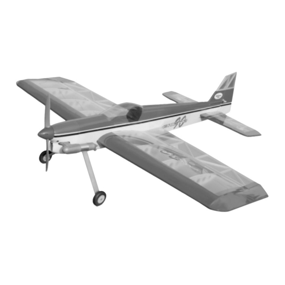
INSTRUCTIONS FOR FINAL ASSEMBLY
The Modeltech Excite 90L ARF is distributed
Specifications:
exclusively by Global Hobby Distributors 18480
Bandilier Circle, Fountain Valley, CA 92708
Wing Span: 61 Inches
Wing Area: 1,100 Square Inches
Wing Loading: 14.5 - 16 Ounces Per Square Foot
Length: 68 Inches
Weight RTF: 7 - 7.5 Pounds
All contents copyright © 2003, Global Hobby
Functions: Ailerons, Elevator, Rudder & Throttle
Distributors Version V1.0 January 2003
Power: .60 - .91 (Small Block) 2-Stroke
Radio: 4 Channel w/4 High-Torque Servos & 1 Standard Servo
Kit Product Number 123751
1
Need help or have any questions? Call us at 1-714-963-0329 or send us an Email at service@globalhobby.net
Advertisement
Table of Contents

Subscribe to Our Youtube Channel
Related Manuals for Modeltech Excite 90


Summary of Contents for Modeltech Excite 90
- Page 1 INSTRUCTIONS FOR FINAL ASSEMBLY The Modeltech Excite 90L ARF is distributed Specifications: exclusively by Global Hobby Distributors 18480 Bandilier Circle, Fountain Valley, CA 92708 Wing Span: 61 Inches Wing Area: 1,100 Square Inches Wing Loading: 14.5 - 16 Ounces Per Square Foot Length: 68 Inches Weight RTF: 7 - 7.5 Pounds...
-
Page 2: Table Of Contents
OUR GUARANTEE Modeltech guarantees this kit to be free from defects in both material and workmanship, at the date of purchase. This does not cover any component parts damaged by use, misuse or modification. In no case shall Modeltech's liability exceed the original cost of the purchased kit. -
Page 3: Introduction
INTRODUCTION Thank you for purchasing the new Modeltech Excite 90L ARF. Before completing the final assembly of your new airplane, please carefully read through this instruction manual in its entirety. Doing so will ensure your success the first time around! -
Page 4: Section 1: Our Recommendations
This section describes our recommendations to help you in deciding which types of accessories to purchase for your new Modeltech Excite 90L ARF. These suggestions are not set in stone, but they should provide you with a good starting point. -
Page 5: Section 2: Tools And Supplies Required
SECTION 2: TOOLS AND SUPPLIES REQUIRED The tools and supplies listed below will be necessary to finish the assembly of your Excite 90L ARF. We suggest having these items on hand before beginning assembly. Electric Drill Kwik Bond Thin C/A # 887500 Kwik Bond Thick C/A # 887510 Assorted Drill Bits Kwik Bond 30 Minute Epoxy # 887565... -
Page 6: Section 4: Metric Conversion Chart
609.6mm 1/16" 1.6mm 3/8" 9.5mm 3" 76.2mm 30" 762.0mm 3/32" 2.4mm 1/2" 12.7mm 6" 152.4mm 36" 914.4mm 1/8" 3.2mm 5/8" 15.9mm 12" 304.8mm 5/32" 4.0mm 3/4" 19.0mm 18" 457.2mm Visit our website at http://modeltech.globalhobby.com or for Customer Service at http://globalservices.globalhobby.com... -
Page 7: Section 5: Replacement Parts
We suggest ordering directly from your local dealer. If your dealer does not stock Modeltech products, you can order directly from us at the address shown below:... -
Page 8: Section 7: Wing Assembly
If it does not fit properly, use 220 grit sandpaper with a sanding block to lightly sand the edges and tips of the joiner, until you are satisfied with the fit. Visit our website at http://modeltech.globalhobby.com or for Customer Service at http://globalservices.globalhobby.com... - Page 9 Slide both wing panels together with the wing joiner temporarily installed (without using glue). Look carefully at the center section joint: the wing panels should fit together tightly with few or no gaps in the joint. If the wing panels do not fit together properly, remove the wing joiner and use 220 grit sandpaper with a sanding block to lightly sand the edges and tips of the joiner, until you are satisfied with the fit.
-
Page 10: Section 8: Wing Mounting & Belly Pan Installation
Make sure that the wing is pushed as far forward as possible. There will be a gap between the trailing edge of the wing and the back of the wing saddle. This is normal and will be covered by the belly pan when it's installed later. Visit our website at http://modeltech.globalhobby.com or for Customer Service at http://globalservices.globalhobby.com... - Page 11 Align the holes in the wing with the preinstalled blind nuts in the wing mounting block inside the fuselage. Secure the wing into place using two M6 x 40 machine screws and two M6 flat washers. Don't overtighten the screws. You don't want to crush the wing.
-
Page 12: Section 9: Stabilizer Installation
When you're satisfied with the alignment of the trailing edge, draw a mark on each side of the stabilizer (at the trailing edge) where it meets the fuselage sides. Visit our website at http://modeltech.globalhobby.com or for Customer Service at http://globalservices.globalhobby.com... - Page 13 With the marks on the stabilizer lined up with the fuselage sides, hold only the trailing edge of the stabilizer in position using a T-Pin. IMPORTANT The front of the stabilizer should be able to pivot from side to side and the back should stay firmly in place and aligned.
- Page 14 Push the stabilizer down into place and realign it, double-checking all of your measurements once more before the epoxy sets up. Quickly remove the excess epoxy and use pieces of masking tape to hold the stabilizer in place until the epoxy has fully cured. Visit our website at http://modeltech.globalhobby.com or for Customer Service at http://globalservices.globalhobby.com...
-
Page 15: Section 10: Control Surface Hinging
SECTION 10: CONTROL SURFACE HINGING YOU'LL NEED THE FOLLOWING PARTS FROM THE KIT: (17) C/A Style Hinges YOU'LL NEED THE FOLLOWING TOOLS AND SUPPLIES: Kwik Bond Thin C/A Ernst Airplane Stand Kwik Bond C/A Debonder Paper Towels Excel Modeling Knife Step 1: Hinging the Ailerons IMPORTANT For flutter-free control surfaces, it is imperative that the hinges be glued in properly. -
Page 16: Section 11: Tail Wheel Installation
The clasp of the tiller arm should fit over the bottom edge of the rudder. Visit our website at http://modeltech.globalhobby.com or for Customer Service at http://globalservices.globalhobby.com... -
Page 17: Section 12: Main Landing Gear Installation
When satisfied with the alignment, drill three 5/64" diameter pilot holes through the fuselage for the wood screws. Mount the tail wheel assembly to the fuselage using three M3 x 12 wood screws. While holding the tiller arm firmly against the bottom of the rudder, drill a 5/64"... -
Page 18: Section 13: Engine Installation
The references in this section are taken from the consideration that you are looking at the front of the airplane with the airplane right-side up. The airplane is designed for the engine to be mounted inverted. Visit our website at http://modeltech.globalhobby.com or for Customer Service at http://globalservices.globalhobby.com... - Page 19 Install the two engine mounting beams using the four M4 x 20 socket-cap screws and four M4 flat washers. Tighten the screws firmly to hold the beams securely in place. IMPORTANT Blind nuts have been preinstalled into the back of the firewall to thread the screws into. IMPORTANT The engine mounting beams are spaced to fit the Magnum XLS .91 two stroke engine.
-
Page 20: Section 14: Fuel Tank Assembly & Installation
Push the M3 x 20 machine screw through the stopper assembly, from the front, and partially thread it into the small diameter metal backplate. Visit our website at http://modeltech.globalhobby.com or for Customer Service at http://globalservices.globalhobby.com... - Page 21 Step 2: Installing the Stopper Assembly Carefully push the stopper assembly into the molded hole in the front of the fuel tank. Gently rotate the stopper assembly until the aluminum vent tube rests just inside the bubble in the top of the tank. If you have trouble seeing the vent tube, hold the fuel tank assembly up to a bright light.
-
Page 22: Section 15: Servo Installation
Install each aileron servo and pull the servo leads out through the exit holes in the top of the wing. Note the position of the servo output shaft. It should be toward the trailing edge of the wing. Visit our website at http://modeltech.globalhobby.com or for Customer Service at http://globalservices.globalhobby.com... -
Page 23: Section 16: Throttle Linkage Installation
SECTION 16: THROTTLE LINKAGE INSTALLATION YOU'LL NEED THE FOLLOWING PARTS FROM THE KIT: (1) Adjustable Servo Connector Assembly (1) 21-3/4" Pushrod Wire w/Z-Bend YOU'LL NEED THE FOLLOWING TOOLS AND SUPPLIES: Kwik Bond Thin C/A Excel Modeling Knife # 1 Phillips Head Screwdriver Electric Drill Wire Cutters 5/64"... -
Page 24: Section 17: Rudder Control System Installation
Using a modeling knife, cut away and remove the covering material from over the rudder pushrod exit holes in each side of the fuselage. The holes are located 6-1/4" in front of the rudder hinge line and 2-3/16" above the top of the horizontal stabilizer. Visit our website at http://modeltech.globalhobby.com or for Customer Service at http://globalservices.globalhobby.com... - Page 25 Connect your radio system and plug the rudder servo into the receiver. Double-check that the rudder trim lever on your transmitter is centered. Carefully slide the pushrod wires into the preinstalled pushrod housings in the rear bulkhead and install the servo horn onto the servo, making sure it's centered.
-
Page 26: Section 18: Elevator Control System Installation
Using a modeling knife, cut away and remove the covering material from over the elevator pushrod exit holes in each side of the fuselage. The holes are located 9-1/4" in front of the rudder hinge line and 1/2" below the bottom of the stabilizer. Visit our website at http://modeltech.globalhobby.com or for Customer Service at http://globalservices.globalhobby.com... - Page 27 Connect your radio system and plug the elevator servo into the receiver. Double-check that the elevator trim lever on your transmitter is centered. Carefully slide the pushrod wires into the preinstalled pushrod housings. Install the servo horn, making sure that it's centered and pointing toward the middle of the fuselage as shown.
-
Page 28: Section 19: Aileron Control System Installation
The centerline of the control horn should be approximately 8-1/8" out from the inside edge of the aileron. Visit our website at http://modeltech.globalhobby.com or for Customer Service at http://globalservices.globalhobby.com... -
Page 29: Section 20: Final Assembly
Thread one clevis onto the pushrod wire and snap it into the outermost hole in the control horn. Repeat the previous steps to install the second aileron pushrod assembly on the opposite wing panel. SECTION 20: FINAL ASSEMBLY YOU'LL NEED THE FOLLOWING PARTS FROM THE KIT: (4) M3 x 5 Wood Screws (1) Prepainted Molded Fiberglass Cowling (4) M3 Flat Washers... - Page 30 Set the canopy onto the fuselage and align it. The canopy should be centered over the middle of the fuselage when looking from the front and it should be centered over the cockpit area when looking from the side. Visit our website at http://modeltech.globalhobby.com or for Customer Service at http://globalservices.globalhobby.com...
- Page 31 When satisfied with the fit and alignment, remove the canopy and carefully apply a thin bead of Pacer Formula 560 Canopy Glue around the inside edges of the canopy. Set the canopy back into place and realign it. Use pieces of masking tape to hold the edges of the canopy firmly in place and remove any excess adhesive using a paper towel soaked with water.
-
Page 32: Section 21: Balancing The Excite 90L Arf
Repeat the procedure a couple of more times to double-check your findings. When done properly the wing should stay level when you lift the airplane. Visit our website at http://modeltech.globalhobby.com or for Customer Service at http://globalservices.globalhobby.com... -
Page 33: Section 23: Control Throws
SECTION 23: CONTROL THROWS We recommend setting up the Excite 90L ARF using the control throws listed below. These control throws are suggested for initial test-flying because they will allow the airplane to fly smoother and make it easier to control. TEST-FLYING Ailerons: 1"... -
Page 34: Section 24: Computer Radio Setup
Use of more than 3/4" of flaperons and spoilerons will cause excessive drag, negating any of their useful effects. We do not recommend using flaperon and spoileron with elevator mixing during general flying, especially during takeoff and landing. Visit our website at http://modeltech.globalhobby.com or for Customer Service at http://globalservices.globalhobby.com... -
Page 35: Section 25: Preflight Check & Safety
SECTION 25: PREFLIGHT CHECK & SAFETY Completely charge the transmitter and receiver batteries before your first day of flying. Check every bolt and every glue joint in the airplane to ensure that everything is tight and well-bonded. This should include all of the control surface hinges as well. Double-check that you've installed and tightened all of the servo horn retaining screws. -
Page 36: Section 26: Flying The Excite 90L Arf
As always, when landing be careful not to over-control. Over-controlling leads to excessive oscillations which don't make for good landings. Visit our website at http://modeltech.globalhobby.com or for Customer Service at http://globalservices.globalhobby.com... -
Page 37: Section 27: Excite 90L Arf Trimming Chart
SECTION 27: EXCITE 90L ARF TRIMMING CHART After you have test-flown and done the initial trim changes to the airplane, use this trimming chart to begin trimming your airplane. Following and adhering to this chart will result in the ability to diagnose trim problems and correct those problems using the simple adjustments shown below. - Page 38 Visit our website at http://modeltech.globalhobby.com or for Customer Service at http://globalservices.globalhobby.com...
-
Page 39: Product Evaluation Sheet
Your privacy is important to us. Was any of the assembly difficult for you? If yes, Kit: Modeltech Excite 90L ARF # 123751 please explain. Where did you learn about this kit? - Page 40 Post Office will not deliver _____________________________ without proper postage (Return Address Here) Global Hobby Distributors Attn: Global Services 18480 Bandilier Circle Fountain Valley CA 92728-8610 Fold along dotted line Visit our website at http://modeltech.globalhobby.com or for Customer Service at http://globalservices.globalhobby.com...
Need help?
Do you have a question about the Excite 90 and is the answer not in the manual?
Questions and answers