Table of Contents
Advertisement
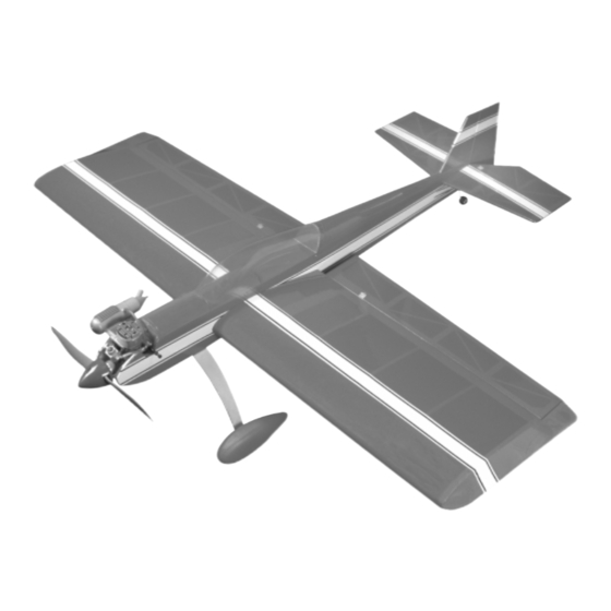
INSTRUCTIONS FOR FINAL ASSEMBLY
The Modeltech Magic Extra 300L ARF is distributed
exclusively by Global Hobby Distributors 18480
Bandilier Circle, Fountain Valley, CA 92708
All contents copyright © 2002, Global Hobby
Distributors Version V2.0 June 2002
Kit Product Number 123739
Need help or have any questions? Call us at 1-714-963-0329 or send us an Email at service@globalhobby.net
Specifications:
Wing Span: 49.5 Inches
Wing Area: 700 Square Inches
Wing Loading: 15-17 Ounces Per Square Foot
Length: 49.5 Inches
Weight RTF: 4.5 - 5.1 Pounds / 72 - 82 Ounces
Functions: Ailerons, Elevator, Rudder and Throttle
Power: .46 2-Stroke (recommended) or .61 4-Stroke
Radio: 4 Channel w/4 Standard Servos
1
Advertisement
Table of Contents

Subscribe to Our Youtube Channel
Related Manuals for Modeltech Magic Extra 300L


Summary of Contents for Modeltech Magic Extra 300L
-
Page 1: Specifications
INSTRUCTIONS FOR FINAL ASSEMBLY Specifications: The Modeltech Magic Extra 300L ARF is distributed Wing Span: 49.5 Inches exclusively by Global Hobby Distributors 18480 Wing Area: 700 Square Inches Bandilier Circle, Fountain Valley, CA 92708 Wing Loading: 15-17 Ounces Per Square Foot Length: 49.5 Inches... -
Page 2: Table Of Contents
OUR GUARANTEE Modeltech guarantees this kit to be free from defects in both material and workmanship, at the date of purchase. This does not cover any component parts damaged by use, misuse or modification. In no case shall Modeltech's liability exceed the original cost of the purchased kit. -
Page 3: Introduction
INTRODUCTION Thank you for purchasing the new Modeltech Magic Extra 300L ARF. Before completing the final assembly of your new airplane, please carefully read through this instruction manual in its entirety. Doing so will ensure your success the first time around! -
Page 4: Section 1: Our Recommendations
This section describes our recommendations to help you in deciding which types of accessories to purchase for your new Modeltech Magic Extra 300L ARF. These suggestions are not set in stone, but they should provide you with a good starting point. -
Page 5: Section 2: Tools And Supplies Required
SECTION 2: TOOLS AND SUPPLIES REQUIRED The tools and supplies listed below will be necessary to finish the final assembly of your Magic Extra 300L. We suggest having these items on-hand before beginning assembly. Kwik Bond Thin C/A # 887500... -
Page 6: Section 4: Metric Conversion Chart
609.6mm 1/16" 1.6mm 3/8" 9.5mm 3" 76.2mm 30" 762.0mm 3/32" 2.4mm 1/2" 12.7mm 6" 152.4mm 36" 914.4mm 1/8" 3.2mm 5/8" 15.9mm 12" 304.8mm 5/32" 4.0mm 3/4" 19.0mm 18" 457.2mm Visit our website at http://modeltech.globalhobby.com or for Customer Service at http://globalservices.globalhobby.com... -
Page 7: Section 5: Replacement Parts
We suggest ordering directly from your local dealer. If your dealer does not stock Modeltech products, you can order directly from us at the address shown below:... -
Page 8: Section 7: Wing Assembly
If it does not fit properly, use 220 grit sandpaper with a sanding block to lightly sand the edges and tips of the joiner, until you are satisfied with the fit. Visit our website at http://modeltech.globalhobby.com or for Customer Service at http://globalservices.globalhobby.com... - Page 9 Slide both wing panels together with the wing joiner temporarily installed (without using glue). Look carefully at the center section joint: the wing panels should fit together tightly with few or no gaps in the joint. If the wing panels do not fit together properly, remove the wing joiner and use 220 grit sandpaper with a sanding block to lightly sand the edges and tips of the joiner, until you are satisfied with the fit.
-
Page 10: Section 8: Wing Mounting
Locate one hole in each wing panel, 3/4" out from the centerline and 1/2" in front of the trailing edge. IMPORTANT Drill the two holes parallel to the bottom surface of the wing. Visit our website at http://modeltech.globalhobby.com or for Customer Service at http://globalservices.globalhobby.com... - Page 11 Step 2: Installing the Blind Nuts Remove the wing from the fuselage and enlarge only the two holes in the plywood wing hold-down block using a 15/64" diameter drill bit. Enlarging the holes will make it much easier to install the blind nuts. Install the two blind nuts into the bottom of the plywood block, using one of the wing mounting screws and washers to draw the blind nuts firmly up into place.
-
Page 12: Section 9: Belly Pan Installation
Set the belly pan back into place and realign it. Use pieces of masking tape to hold it securely in place and remove any excess epoxy using a paper towel and rubbing alcohol. After the epoxy has fully cured, remove the masking tape, but leave the wing in place for now. Visit our website at http://modeltech.globalhobby.com or for Customer Service at http://globalservices.globalhobby.com... -
Page 13: Section 10: Stabilizer Installation
SECTION 10: STABILIZER INSTALLATION YOU'LL NEED THE FOLLOWING PARTS FROM THE KIT: (1) Vertical Stabilizer w/Rudder (1) Horizontal Stabilizer w/Elevator Halves YOU'LL NEED THE FOLLOWING TOOLS AND SUPPLIES: Kwik Bond 30 Minute Epoxy 220 Grit Sandpaper w/Sanding Block Excel Modeling Knife Masking Tape Dubro T-Pins Paper Towels... - Page 14 Push the stabilizer back into place and realign it, double-checking all of your measurements once more before the epoxy sets up. Quickly remove the excess epoxy and use pieces of masking tape to hold the stabilizer in place until the epoxy has fully cured. Visit our website at http://modeltech.globalhobby.com or for Customer Service at http://globalservices.globalhobby.com...
- Page 15 After the epoxy has fully cured, remove the masking tape and look closely at the glue joint. If there are any gaps between the stabilizer and the fuselage, fill them using 30 minute epoxy for added strength. Again, before the epoxy sets up, remove any excess using a paper towel and rubbing alcohol.
-
Page 16: Section 11: Control Surface Hinging
Remove any C/A that may run down the hinge line using C/A Debonder. Allow the C/A to dry for about 15 minutes, then pivot the aileron up and down to free up the hinges. Visit our website at http://modeltech.globalhobby.com or for Customer Service at http://globalservices.globalhobby.com... - Page 17 Repeat the previous procedures to hinge the second aileron to the other wing panel. IMPORTANT After the C/A has fully cured, gently grasp each aileron and pull on it like you are trying to pull out the hinges. The hinges should hold securely.
-
Page 18: Section 12: Main Landing Gear Installation
Install the main gear strut using the two 4mm x 16mm machine screws, four 4mm flat washers and two 4mm lock nuts. To make it easier to install and tighten the lock nuts, remove the hatch cover from the top of the fuselage. Visit our website at http://modeltech.globalhobby.com or for Customer Service at http://globalservices.globalhobby.com... - Page 19 Step 2: Installing the Wheels and Wheel Pants Using a modeling knife, very carefully cut the wheel opening in each of the two wheel pants, as shown. Use 220 grit sandpaper with a sanding block to sand the edges of the openings smooth. Using a 5/32"...
-
Page 20: Section 13: Engine Installation
Using a ruler and a pencil, measure up 2" from the bottom of the firewall and draw a horizontal line. This will be referred to as the "horizontal centerline." Visit our website at http://modeltech.globalhobby.com or for Customer Service at http://globalservices.globalhobby.com... - Page 21 Using a ruler and a pencil, measure and draw one horizontal line 1/2" above the horizontal centerline and one horizontal line 13/16" below the horizontal centerline. Temporarily glue the two engine mounting beams to your engine's mounting lugs using a couple of drops of thick C/A. The location of the engine is not important at this time.
-
Page 22: Section 14: Fuel Tank Assembly & Installation
This distance should be 3/8". If it is not, adjust the tubes by pushing them forward or backward until you are satisfied with the alignment. Visit our website at http://modeltech.globalhobby.com or for Customer Service at http://globalservices.globalhobby.com... - Page 23 Carefully bend the longer of the two aluminum tubes up at a 45º angle, being careful not to "kink" the tubing as you bend it. When the stopper assembly is installed in the fuel tank, the top of the vent tube (the tube you just bent) should rest just below the top of the tank.
-
Page 24: Section 15: Servo Installation
Install the servos and pull the servo leads out through the exit holes in the top of the wing. Note the position of the servo output shaft. It should be toward the trailing edge of the wing. Visit our website at http://modeltech.globalhobby.com or for Customer Service at http://globalservices.globalhobby.com... -
Page 25: Section 16: Throttle Linkage Installation
SECTION 16: THROTTLE LINKAGE INSTALLATION YOU'LL NEED THE FOLLOWING PARTS FROM THE KIT: (1) 26-1/4" Pushrod Wire w/Z-Bend (1) Adjustable Servo Connector Assembly YOU'LL NEED THE FOLLOWING TOOLS AND SUPPLIES: Kwik Bond Thin C/A Excel Modeling Knife # 1 Phillips Head Screwdriver Electric Drill Wire Cutters 5/64"... -
Page 26: Section 17: Elevator Control System Installation
When installing the snap keeper, make sure it "snaps" firmly into place over the pushrod wire. The pushrod wire should be on top of the servo arm as shown. Visit our website at http://modeltech.globalhobby.com or for Customer Service at http://globalservices.globalhobby.com... - Page 27 Partially thread the 3mm x 8mm set screws into the wheel collars. Slide the wheel collars onto the elevator pushrod wire and up against the snap keeper. Make a shallow bend 1-1/2" from the plain end of the 13-1/2" long pushrod wire and slide the pushrod wire through the wheel collars as shown.
-
Page 28: Section 18: Rudder Control System Installation
When installing the snap keepers, make sure they "snap" firmly into place over the pushrod wires. The pushrod wires should be on top of the servo arms as shown. Visit our website at http://modeltech.globalhobby.com or for Customer Service at http://globalservices.globalhobby.com... - Page 29 Using a modeling knife, cut away and remove the covering material from over the rudder pushrod exit holes in each side of the fuselage. They are located 5-1/4" in front of the rudder hinge line and 1-1/4" above the bottom of the fuselage. Connect your radio system and plug the rudder servo into the receiver.
-
Page 30: Section 19: Aileron Control System Installation
The centerline of the control horn should be approximately 5" out from the inside edge of the aileron. Visit our website at http://modeltech.globalhobby.com or for Customer Service at http://globalservices.globalhobby.com... -
Page 31: Section 20: Final Assembly
Thread the clevis onto the pushrod wire and snap it into the outermost hole from the base of the control horn. Repeat the previous steps to install the second aileron pushrod assembly on the opposite wing panel. SECTION 20: FINAL ASSEMBLY YOU'LL NEED THE FOLLOWING PARTS FROM THE KIT: (1) Clear Molded Canopy (2) 2mm x 10mm Wood Screws... - Page 32 Wrap the receiver and battery in foam rubber to protect them from vibration. Use masking tape or rubber bands to hold the foam in place. Do not wrap the foam rubber too tightly or the vibration dampening quality will be reduced. Visit our website at http://modeltech.globalhobby.com or for Customer Service at http://globalservices.globalhobby.com...
-
Page 33: Section 21: Balancing The Magic Extra 300L
Attach a piece of scrap wire to the switch that runs out the side of the fuselage. You can then turn the switch on and off by pushing and pulling the piece of wire. SECTION 21: BALANCING THE MAGIC EXTRA 300L YOU'LL NEED THE FOLLOWING TOOLS AND SUPPLIES:... -
Page 34: Section 22: Lateral Balancing The Magic Extra 300L
SECTION 23: CONTROL THROWS We recommend setting up the Magic Extra 300L using the control throws listed below. These control throws are suggested for initial test-flying because they will allow the airplane to fly smoother and make it easier to control. -
Page 35: Section 24: Preflight Check & Safety
SECTION 24: PREFLIGHT CHECK & SAFETY Completely charge the transmitter and receiver batteries before your first day of flying. Check every bolt and every glue joint in the airplane to ensure that everything is tight and well-bonded. This should include all of the control surface hinges as well. Double-check that you've installed and tightened all of the servo horn retaining screws. -
Page 36: Section 25: Flying The Magic Extra 300L
TAKE-OFF Because the Magic Extra 300L is light and has a lot of power, it sometimes seems like it wants to take off by itself. Do be aware that it's still important to let the airplane get up to flying speed before lifting off the ground. Lifting the airplane off the ground too fast will cause the airplane to stall and crash. -
Page 37: Section 26: Magic Extra 300L Trimming Chart
SECTION 26: MAGIC EXTRA 300L TRIMMING CHART After you have test-flown and done the initial trim changes to the airplane, use this trimming chart to begin trimming your airplane. Following and adhering to this chart will result in the ability to diagnose trim problems and correct those problems using the simple adjustments shown below. - Page 38 Visit our website at http://modeltech.globalhobby.com or for Customer Service at http://globalservices.globalhobby.com...
-
Page 39: Product Evaluation Sheet
Your privacy is important to us. Was any of the assembly difficult for you? If yes, Kit: Modeltech Magic Extra 300L ARF # 123739 please explain. Where did you learn about this kit? - Page 40 Post Office will not deliver _____________________________ without proper postage (Return Address Here) Global Hobby Distributors Attn: Global Services 18480 Bandilier Circle Fountain Valley CA 92728-8610 Fold along dotted line Visit our website at http://modeltech.globalhobby.com or for Customer Service at http://globalservices.globalhobby.com...
Need help?
Do you have a question about the Magic Extra 300L and is the answer not in the manual?
Questions and answers