
Subscribe to Our Youtube Channel
Related Manuals for Gigabyte GA-J1800M-D2P


Summary of Contents for Gigabyte GA-J1800M-D2P
- Page 1 GA-J1800M-D2P GA-J1900M-D2P User's Manual Rev. 1102 12ME-J18MD2P-1102R GA-J1800M-D2P GA-J1900M-D2P...
-
Page 2: Identifying Motherboard Revision
Information in this manual is protected by copyright laws and is the property of GIGABYTE. Changes to the specifications and features in this manual may be made by GIGABYTE without prior notice. No part of this manual may be reproduced, copied, translated, transmitted, or published in any form or by any means without GIGABYTE's prior written permission. -
Page 3: Table Of Contents
Table of Contents GA-J1800M-D2P/GA-J1900M-D2P Motherboard Layout ..........4 GA-J1800M-D2P/GA-J1900M-D2P Motherboard Block Diagram ........5 Chapter 1 Hardware Installation ..................6 Installation Precautions ................... 6 Product Specifications ..................7 Installing the Memory ..................9 Installing an Expansion Card ................9 Back Panel Connectors ................... 9 Internal Connectors ..................11... -
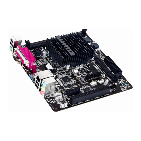
Page 4: Ga-J1800M-D2P/Ga-J1900M-D2P Motherboard Layout
PCIEX1 F_PANEL CLR_CMOS CODEC Box Contents 5 GA-J1800M-D2P or GA-J1900M-D2P motherboard 5 Motherboard driver disk 5 Two SATA cables 5 User's Manual 5 I/O Shield The box contents above are for reference only and the actual items shall depend on the product package you obtain. -
Page 5: Ga-J1800M-D2P/Ga-J1900M-D2P Motherboard Block Diagram
GA-J1800M-D2P/GA-J1900M-D2P Motherboard Block Diagram DDR3/-L 1333 MHz Dual Channel Memory HDMI D-Sub BIOS 2 SATA 3Gb/s 1 PCI Express x1 1 USB 3.0/2.0 Intel J1800 SoC j ® Intel J1900 SoC k ® 8 USB 2.0/1.1 PCI Express Bus PCIe CLK... -
Page 6: Chapter 1 Hardware Installation
Chapter 1 Hardware Installation Installation Precautions The motherboard contains numerous delicate electronic circuits and components which can become damaged as a result of electrostatic discharge (ESD). Prior to installation, carefully read the user's manual and follow these procedures: • Prior to installation, make sure the chassis is suitable for the motherboard. •... -
Page 7: 1-2 Product Specifications
1 x S/PDIF Out header Š 2 x USB 2.0/1.1 headers Š 2 x serial port headers Š 1 x chassis intrusion header Š 1 x Clear CMOS jumper Š j Only for GA-J1800M-D2P. k Only for GA-J1900M-D2P. - 7 -... - Page 8 Micro ATX Form Factor; 19.0cm x 18.0cm Š * GIGABYTE reserves the right to make any changes to the product specifications and product-related information without prior notice. * Please visit the Support & Downloads\Utility page on GIGABYTE's website to check the supported operating system(s) for the software listed in the "Unique Features"...
-
Page 9: Installing The Memory
• Make sure that the motherboard supports the memory. It is recommended that memory of the same capacity, brand, speed, and chips be used. (Go to GIGABYTE's website for the latest supported memory speeds and memory modules.) • Always turn off the computer and unplug the power cord from the power outlet before installing the memory to prevent hardware damage. - Page 10 D-Sub Port The D-Sub port supports a 15-pin D-Sub connector and supports a maximum resolution of 2560x1600 (the actual resolutions supported depend on the monitor being used). Connect a monitor that supports D-Sub connection to this port. HDMI Port The HDMI port is HDCP compliant and supports Dolby True HD and DTS HD Master Audio formats.
-
Page 11: Internal Connectors
Internal Connectors 10 11 ATX_12V F_PANEL CPU_FAN F_AUDIO SYS_FAN SPDIF_O SATA2 0/1 F_USB1/F_USB2 COMA/COMB CLR_CMOS Read the following guidelines before connecting external devices: • First make sure your devices are compliant with the connectors you wish to connect. • Before installing the devices, be sure to turn off the devices and your computer. Unplug the power cord from the power outlet to prevent damage to the devices. - Page 12 1/2) ATX_12V/ATX (2x2 12V Power Connector and 2x12 Main Power Connector) With the use of the power connector, the power supply can supply enough stable power to all the components on the motherboard. Before connecting the power connector, first make sure the power supply is turned off and all devices are properly installed.
- Page 13 5) SATA2 0/1 (SATA 3Gb/s Connectors) The SATA connectors conform to SATA 3Gb/s standard and are compatible with SATA 1.5Gb/s standard. Each SATA connector supports a single SATA device. Pin No. Definition SATA2 6) BAT (Battery) The battery provides power to keep the values (such as BIOS configurations, date, and time information) in the CMOS when the computer is turned off.
- Page 14 9) F_PANEL (Front Panel Header) Connect the power switch, reset switch, and system status indicator on the chassis to this header according to the pin assignments below. Note the positive and negative pins before connecting the cables. • PLED (Power LED, Yellow): Power Switch Power LED Connects to the power status indicator on the chassis...
- Page 15 11) SPDIF_O (S/PDIF Out Header) This header supports digital S/PDIF Out and connects a S/PDIF digital audio cable (provided by expansion cards) for digital audio output from your motherboard to certain expansion cards like graphics cards and sound cards. For example, some graphics cards may require you to use a S/PDIF digital audio cable for digital audio output from your motherboard to your graphics card if you wish to connect an HDMI display to the graphics card and have digital audio output from the HDMI display at the same time.
-
Page 16: Chapter 2 Bios Setup
To access the BIOS Setup program, press the <Delete> key during the POST when the power is turned on. To upgrade the BIOS, use the GIGABYTE @BIOS utility, which is a Windows-based utility that searches and downloads the latest version of BIOS from the Internet and updates the BIOS. -
Page 17: Main
Press <Esc> to exit the help screen. Help for each item is in the Item Help block on the right side of the submenu. (Sample BIOS Version: GA-J1800M-D2P E13) • When the system is not stable as usual, select the Restore Defaults item to set your system to its defaults. -
Page 18: Advanced
Advanced Aptio Setup Utility - Copyright (C) 2013 American Megatrends, Inc. Main Advanced Chipset Security Boot Save & Exit Resume by Alarm [Disabled] Wale up day Wake up hour Wake up minute Wake up second Power Loading [Auto] DDR Voltage Control [Auto] ` Hardware Monitor ` Intel(R) Smart Connect Technology... - Page 19 ` SIO Misc Functions & ErP Determines whether to let the system consume least power in S5 (shutdown) state. (Default: Disabled) Note: When this item is set to Enabled, the following functions will become unavailable: Resume by Alarm, PME event wake up, power on by mouse, power on by keyboard, and wake on LAN. &...
- Page 20 ` PPM Configuration & CPU C state Report Enables or disables support for CPU's power-saving functions. (Default: Enabled) & Enhanced C state Enables or disables Intel CPU Enhanced Halt (C1E) function, a CPU power-saving function in system ® halt state. When enabled, the CPU core frequency and voltage will be reduced during system halt state to decrease power consumption.
-
Page 21: Ipv6 Pxe Support
& Ipv6 PXE Support Enables or disables IPv6 PXE Support. This item is configurable only when Network stack is enabled. ` CSM Configuration & CSM Support Enables or disables UEFI CSM (Compatibility Support Module) to support a legacy PC boot process. Enables UEFI CSM. -
Page 22: Chipset
` USB Configuration & Legacy USB Support Allows USB keyboard/mouse to be used in MS-DOS. (Default: Enabled) & USB3.0 Support Enables or disables the USB 3.0 controller. (Default: Enabled) & XHCI Hand-off Determines whether to enable XHCI Hand-off feature for an operating system without XHCI Hand-off support. -
Page 23: Security
` North Bridge This section provides information on the installed memory size and memory/onboard graphics-related configuration options. ` Intel IGD Configuration This section provides onboard graphics-related configuration options. & MAX TOLUD Allows you to configure the maximum TOLUD value. (Default: Dynamic) ` South Bridge This section provides information on the installed memory size and memory/onboard graphics-related configuration options. -
Page 24: Administrator Password
& Administrator Password Allows you to configure an administrator password. Press <Enter> on this item, type the password, and then press <Enter>. You will be requested to confirm the password. Type the password again and press <Enter>. You must enter the administrator password (or user password) at system startup and when entering BIOS Setup. -
Page 25: Boot
Enables or disables Numlock feature on the numeric keypad of the keyboard after the POST. (Default: On) & Full Screen LOGO Show Allows you to determine whether to display the GIGABYTE Logo at system startup. Disabled skips the GIGABYTE Logo when the system starts up. (Default: Enabled) &... -
Page 26: Save & Exit
& Boot Option #1/2/3 Specifies the overall boot order from the available devices. For example, you can set hard drive as the first priority (Boot Option #1) and DVD ROM drive as the second priority (Boot Option #2). The list only displays the device with the highest priority for a specific type. -
Page 27: Chapter 3 Appendix
& Restore User Defaults Load the user-define default settings for all BIOS options. & Boot Override Allows you to select a device to boot immediately. Press <Enter> on the device you select and select Yes to confirm. Your system will restart automatically and boot from that device. &... -
Page 28: Regulatory Statements
Contravention will be prosecuted. We believe that the information contained herein was accurate in all respects at the time of printing. GIGABYTE cannot, however, assume any responsibility for errors or omissions in this text. Also note that the information in this document is subject to change without notice and should not be construed as a commitment by GIGABYTE. - Page 29 FCC Notice (U.S.A. Only) This equipment has been tested and found to comply with the limits for a Class B digital device, pursuant to Part 15 of the FCC Rules. These limits are designed to provide reasonable protection against harmful interference in a residential installation.
- Page 30 - 30 -...
- Page 31 - 31 -...
-
Page 32: Contact Us
Tech. and Non-Tech. Support (Sales/Marketing) : http://esupport.gigabyte.com WEB address (English): http://www.gigabyte.com WEB address (Chinese): http://www.gigabyte.tw You may go to the GIGABYTE website, select your language in the language list on the top right corner of the website. GIGABYTE eSupport •...
Need help?
Do you have a question about the GA-J1800M-D2P and is the answer not in the manual?
Questions and answers