Table of Contents

Related Manuals for Gigabyte GA-H67A-USB3-B3


Summary of Contents for Gigabyte GA-H67A-USB3-B3
- Page 1 GA-H67A-USB3-B3 LGA1155 socket motherboard for Intel Core i7 processors/ ® ™ Intel Core i5 processors/Intel Core i3 processors/ ® ™ ® ™ Intel Pentium processors/Intel Celeron processors ® ® ® ® User's Manual Rev. 1001 12ME-H67AB3B-1001R...
-
Page 3: Identifying Motherboard Revision
GIGABYTE's prior written permission. Documentation Classifications In order to assist in the use of this product, GIGABYTE provides the following types of documentations: For quick set-up of the product, read the Quick Installation Guide included with the product. -
Page 4: Table Of Contents
Table of Contents Box Contents ........................6 Optional Items .........................6 GA-H67A-USB3-B3 Motherboard Layout ................7 GA-H67A-USB3-B3 Motherboard Block Diagram ............8 Chapter 1 Hardware Installation ..................9 Installation Precautions ..................9 1-2 Product Specifications ..................10 Installing the CPU and CPU Cooler ............... 13 1-3-1 Installing the CPU ....................13 1-3-2 Installing the CPU Cooler ..................15... - Page 5 Chapter 3 Drivers Installation ..................55 Installing Chipset Drivers ................55 Application Software ..................56 Technical Manuals ..................56 Contact ......................57 System ......................57 Download Center ................... 58 New Utilities ....................58 Chapter 4 Unique Features ...................59 Xpress Recovery2 ..................59 BIOS Update Utilities ..................
-
Page 6: Box Contents
Box Contents GA-H67A-USB3-B3 motherboard Motherboard driver disk User's Manual Quick Installation Guide Two SATA cables I/O Shield • The box contents above are for reference only and the actual items shall depend on the product package you obtain. The box contents are subject to change without notice. •... -
Page 7: Ga-H67A-Usb3-B3 Motherboard Layout
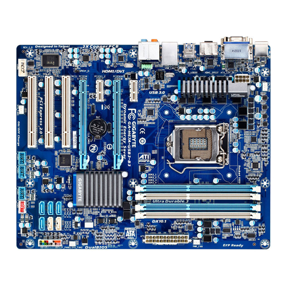
GA-H67A-USB3-B3 Motherboard Layout CPU_FAN KB_USB ATX_12V_2X PHASE LED VGA_DVI LGA1155 HDMI_SPDIF R_USB30 USB_LAN Renesas D720200 AUDIO PCIEX1_1 F_AUDIO GA-H67A-USB3-B3 PCIEX16 Realtek RTL8111E B_BIOS PCIEX1_2 M_BIOS Intel ® CODEC CLR_CMOS PCIEX4 SYS_FAN2 SPDIF_O PCI1 iTE IT8892 Bridge SATA2_3 SATA3_0 PCI2 SATA2_4 SATA3_1 IT8728 PCI3... -
Page 8: Ga-H67A-Usb3-B3 Motherboard Block Diagram
GA-H67A-USB3-B3 Motherboard Block Diagram 1 PCI Express x16 CPU CLK+/- (100 MHz) PCIe CLK LGA1155 DDR3 1333/1066/800 MHz (100 MHz) Dual Channel Memory PCI Express Bus 1 PCI Express x4 2 PCI Express x1 HDMI 2 USB 3.0/2.0 DVI-D D-Sub Renesas D720200 Dual BIOS... -
Page 9: Chapter 1 Hardware Installation
Chapter 1 Hardware Installation Installation Precautions The motherboard contains numerous delicate electronic circuits and components which can become damaged as a result of electrostatic discharge (ESD). Prior to installation, carefully read the user's manual and follow these procedures: • Prior to installation, do not remove or break motherboard S/N (Serial Number) sticker or warranty sticker provided by your dealer. -
Page 10: Product Specifications
Dual channel memory architecture Š Support for DDR3 1333/1066/800 MHz memory modules Š Support for non-ECC memory modules Š (Go to GIGABYTE's website for the latest supported memory speeds and memory modules.) Onboard Integrated in the North Bridge: Š Graphics... - Page 11 Storage Interface Chipset: Š 2 x SATA 6Gb/s connectors (SATA3_0~SATA3_1) supporting up to 2 SATA 6Gb/s devices 4 x SATA 3Gb/s connectors (SATA2_2~SATA2_5) supporting up to 4 SATA 3Gb/s devices Support for SATA RAID 0, RAID 1, RAID 5, and RAID 10 * When a RAID set is built across the SATA 6Gb/s and SATA 3Gb/s channels, the system performance of the RAID set may vary depending on the devices being connected.
- Page 12 Support for Microsoft Windows 7/Vista/XP Š ® System Form Factor ATX Form Factor; 30.5cm x 24.4cm Š * GIGABYTE reserves the right to make any changes to the product specifications and product-related information without prior notice. Hardware Installation - 12 -...
-
Page 13: Installing The Cpu And Cpu Cooler
Read the following guidelines before you begin to install the CPU: • Make sure that the motherboard supports the CPU. (Go to GIGABYTE's website for the latest CPU support list.) • Always turn off the computer and unplug the power cord from the power outlet before installing the CPU to prevent hardware damage. - Page 14 B. Follow the steps below to correctly install the CPU into the motherboard CPU socket. Before installing the CPU, make sure to turn off the computer and unplug the power cord from the power outlet to prevent damage to the CPU. Step 1: Step 2: Gently press the CPU socket lever handle down...
-
Page 15: Installing The Cpu Cooler
1-3-2 Installing the CPU Cooler Follow the steps below to correctly install the CPU cooler on the motherboard. (The following procedure uses Intel boxed cooler as the example cooler.) ® Male Push Direction of the Arrow Sign on The Top the Male Push of Female Push Pin... -
Page 16: Installing The Memory
• Make sure that the motherboard supports the memory. It is recommended that memory of the same capacity, brand, speed, and chips be used. (Go to GIGABYTE's website for the latest supported memory speeds and memory modules.) • Always turn off the computer and unplug the power cord from the power outlet before installing the memory to prevent hardware damage. -
Page 17: Installing A Memory
1-4-2 Installing a Memory Before installing a memory module, make sure to turn off the computer and unplug the power cord from the power outlet to prevent damage to the memory module. DDR3 and DDR2 DIMMs are not compatible to each other or DDR DIMMs. Be sure to install DDR3 DIMMs on this motherboard. -
Page 18: Installing An Expansion Card
Installing an Expansion Card Read the following guidelines before you begin to install an expansion card: • Make sure the motherboard supports the expansion card. Carefully read the manual that came with your expansion card. • Always turn off the computer and unplug the power cord from the power outlet before installing an expansion card to prevent hardware damage. -
Page 19: Back Panel Connectors
Back Panel Connectors USB 2.0/1.1 Port The USB port supports the USB 2.0/1.1 specification. Use this port for USB devices such as a USB key- board/mouse, USB printer, USB flash drive and etc. PS/2 Keyboard/Mouse Port Use this port to connect a PS/2 keyboard or mouse. D-Sub Port The D-Sub port supports a 15-pin D-Sub connector. Connect a monitor that supports D-Sub connection to this port. DVI-D Port (Note) The DVI-D port conforms to the DVI-D specification and supports a maximum resolution of 1920x1200 (the... - Page 20 USB 3.0/2.0 Port The USB 3.0 port supports the USB 3.0 specification and is compatible to the USB 2.0/1.1 specification. Use this port for USB devices such as a USB keyboard/mouse, USB printer, USB flash drive and etc. RJ-45 LAN Port The Gigabit Ethernet LAN port provides Internet connection at up to 1 Gbps data rate. The following de- scribes the states of the LAN port LEDs. Connection/ Speed LED Activity LED Connection/Speed LED: Activity LED: State Description...
-
Page 21: Internal Connectors
Internal Connectors ATX_12V _2X F_PANEL F_AUDIO CPU_FAN SPDIF_O SYS_FAN1/SYS_FAN2 F_USB1/F_USB2/F_USB3/F_USB4 PWR_FAN COMA CLR_CMOS SATA3_0/1 PHASE LED SATA2_2/3/4/5 Read the following guidelines before connecting external devices: • First make sure your devices are compliant with the connectors you wish to connect. • Before installing the devices, be sure to turn off the devices and your computer. - Page 22 1/2) ATX_12V_2X/ATX (2x4 12V Power Connector and 2x12 Main Power Connector) With the use of the power connector, the power supply can supply enough stable power to all the com- ponents on the motherboard. Before connecting the power connector, first make sure the power supply is turned off and all devices are properly installed. The power connector possesses a foolproof design. Connect the power supply cable to the power connector in the correct orientation.
-
Page 23: Cpu_Fan/Sys_Fan1/Sys_Fan2/Pwr_Fan Fan Headers
3/4/5) CPU_FAN/SYS_FAN1/SYS_FAN2/PWR_FAN (Fan Headers) The motherboard has a 4-pin CPU fan header (CPU_FAN), a 4-pin (SYS_FAN1) and a 3-pin system fans, and a 3-pin power fan. Most fan headers possess a foolproof insertion design. When connecting a fan cable, be sure to connect it in the correct orientation (the black connector wire is the ground wire). The motherboard supports CPU fan speed control, which requires the use of a CPU fan with fan speed control design. - Page 24 DEBUG PORT DEBUG PORT 7) SATA3_0/1 (SATA 6Gb/s Connectors, Controlled by H67 Chipset) The SATA connectors conform to SATA 6Gb/s standard and are compatible with SATA 3Gb/s and SATA 1.5Gb/s standard. Each SATA connector supports a single SATA device. The SATA3_0 and SATA3_1 connectors support RAID 0 and RAID 1.
-
Page 25: F_Panel Front Panel Header
9) F_PANEL (Front Panel Header) Connect the power switch, reset switch, speaker, chassis intrusion switch/sensor and system status indicator on the chassis to this header according to the pin assignments below. Note the positive and negative pins before connecting the cables. SPEAK- PWR- Power LED... -
Page 26: Front Panel Audio Header
10) F_AUDIO (Front Panel Audio Header) The front panel audio header supports Intel High Definition audio (HD) and AC'97 audio. You may connect your chassis front panel audio module to this header. Make sure the wire assignments of the module con- nector match the pin assignments of the motherboard header. Incorrect connection between the module connector and the motherboard header will make the device unable to work or even damage it. For HD Front Panel Audio: For AC'97 Front Panel Audio: Pin No. -
Page 27: Serial Port Header
12) F_USB1/F_USB2/F_USB3/F_USB4 (USB Headers) The headers conform to USB 2.0/1.1 specification. Each USB header can provide two USB ports via an optional USB bracket. For purchasing the optional USB bracket, please contact the local dealer. Pin No. Definition Power (5V) Power (5V) USB DX- USB DY- USB DX+ USB DY+ No Pin When the system is in S4/S5 mode, only the USB ports routed to the F_USB1 header can sup- port the ON/OFF Charge function. -
Page 28: Clearing Cmos Jumper
14) CLR_CMOS (Clearing CMOS Jumper) Use this jumper to clear the CMOS values (e.g. date information and BIOS configurations) and reset the CMOS values to factory defaults. To clear the CMOS values, place a jumper cap on the two pins to temporarily short the two pins or use a metal object like a screwdriver to touch the two pins for a few seconds. -
Page 29: Chapter 2 Bios Setup
To see more advanced BIOS Setup menu options, you can press <Ctrl> + <F1> in the main menu of the BIOS Setup program. To upgrade the BIOS, use either the GIGABYTE Q-Flash or @BIOS utility. Q-Flash allows the user to quickly and easily upgrade or back up BIOS without entering the operating •... -
Page 30: Startup Screen
Startup Screen The following screens may appear when the computer boots. A. The LOGO Screen (Default) Function Keys B. The POST Screen Award Modular BIOS v6.00PG Copyright (C) 1984-2010, Award Software, Inc. H67A-USB3-B3 E12c Motherboard Model BIOS Version Function Keys <DEL>: BIOS Setup <F9>: XpressRecovery2 <F12>: Boot Menu <End>: Qflash 12/31/2010-H67-7A89UG0WC-00 Function Keys:... -
Page 31: The Main Menu
The Main Menu Once you enter the BIOS Setup program, the Main Menu (as shown below) appears on the screen. Use ar- row keys to move among the items and press <Enter> to accept or enter a sub-menu. (Sample BIOS Version: E12c) CMOS Setup Utility-Copyright (C) 1984-2010 Award Software MB Intelligent Tweaker(M.I.T.) Load Fail-Safe Defaults... - Page 32 The Functions of the <F11> and <F12> keys (For the Main Menu Only) F11: Save CMOS to BIOS This function allows you to save the current BIOS settings to a profile. You can create up to 8 profiles (Profile 1-8) and name each profile. First enter the profile name (to erase the default profile name, use the SPACE key) and then press <Enter> to complete. F12: Load CMOS from BIOS If your system becomes unstable and you have loaded the BIOS default settings, you can use this function to load the BIOS settings from a profile created before, without the hassles of reconfiguring the BIOS settings. First select the profile you wish to load, then press <Enter> to complete.
-
Page 33: Mb Intelligent Tweaker(M.i.t.)
MB Intelligent Tweaker(M.I.T.) CMOS Setup Utility-Copyright (C) 1984-2010 Award Software MB Intelligent Tweaker(M.I.T.) Item Help M.I.T Current Status [Press Enter] Menu Level Advanced Frequency Settings [Press Enter] Advanced Memory Settings [Press Enter] Advanced Voltage Settings [Press Enter] ... -
Page 34: Cpu Clock Ratio
M.I.T. Current Status This screen provides information on CPU/memory frequencies/parameters. Advanced Frequency Settings CMOS Setup Utility-Copyright (C) 1984-2010 Award Software Advanced Frequency Settings Item Help CPU Clock Ratio [31X] Menu Level CPU Frequency 3.10GHz (100x31) Advanced CPU Core Features [Press Enter] >>>>>... - Page 35 Intel(R) Turbo Boost Tech. (Note) Allows you to determine whether to enable the Intel CPU Turbo Boost technology. Auto lets the BIOS automatically configure this setting. (Default: Auto) Turbo Ratio (1-Core)/(2-Core)/(3-Core)/(4-Core) (Note) Allows you to set the CPU Turbo ratios for different number of active cores. Auto sets the CPU Turbo ratios according to the CPU specifications. (Default: Auto) Turbo Power Limit (Watts) Allows you to set a power limit for CPU Turbo mode.
- Page 36 Bi-Directional PROCHOT (Note) Auto Lets the BIOS automatically configure this setting. (Default) Enabled When the CPU or chipset detects that an overheating is occurring, PROCHOT signals will be emitted to lower CPU performance to decrease heat production. Disabled Only allows the CPU to detect whether an overheating is occurring to emit PROCHOT signals.
- Page 37 Advanced Memory Settings CMOS Setup Utility-Copyright (C) 1984-2010 Award Software Advanced Memory Settings Item Help System Memory Multiplier (SPD) [Auto] Menu Level Memory Frequency (Mhz) 1066 1066 Performance Enhance [Turbo] DRAM Timing Selectable (SPD) [Auto] Profile DDR Voltage 1.5V Profile VTT Voltage 1.05V x Channel Interleaving Auto x Rank Interleaving...
- Page 38 >>>>> Channel A/B Timing Settings CMOS Setup Utility-Copyright (C) 1984-2010 Award Software Channel A Timing Settings Item Help >>>>> Channel A Standard Timing Control Menu Level x CAS Latency Time Auto x tRCD Auto x tRP Auto x tRAS Auto >>>>>...
- Page 39 tFAW Options are: Auto (default), 1~63. Command Rate(CMD) Options are: Auto (default), 1~3. >>>>> Channel A/B Misc Timing Control IO Latency Options are: Auto (default), 1~31. Round Trip Latency Options are: Auto (default), 1~255. Advanced Voltage Settings CMOS Setup Utility-Copyright (C) 1984-2010 Award Software Advanced Voltage Settings Item Help ****** Mother Board Voltage Control ******...
-
Page 40: Miscellaneous Settings
>>> MCH/ICH PCH Core The default is Auto. CPU PLL The default is Auto. DRAM Voltage The default is Auto. DRAM Termination The default is Auto. Ch-A Data VRef. The default is Auto. Ch-B Data VRef. The default is Auto. Ch-A Address VRef. -
Page 41: Standard Cmos Features
Standard CMOS Features CMOS Setup Utility-Copyright (C) 1984-2010 Award Software Standard CMOS Features Item Help Date (mm:dd:yy) Thu, Jan 6 2011 Menu Level Time (hh:mm:ss) 22:31:24 IDE Channel 0 Master [None] IDE Channel 0 Slave [None] IDE Channel 1 Master [None] ... - Page 42 The following fields display your hard drive specifications. If you wish to enter the parameters manually, refer to the information on the hard drive. Capacity Approximate capacity of the currently installed hard drive. Cylinder Number of cylinders. Head Number of heads. Precomp Write precompensation cylinder. Landing Zone Landing zone. Sector Number of sectors. Halt On Allows you to determine whether the system will stop for an error during the POST.
-
Page 43: Advanced Bios Features
Advanced BIOS Features CMOS Setup Utility-Copyright (C) 1984-2010 Award Software Advanced BIOS Features Item Help Hard Disk Boot Priority [Press Enter] Menu Level Quick Boot [Disabled] CD/DVD Boot option [Auto] First Boot Device [Hard Disk] Second Boot Device [CDROM] Third Boot Device [USB-FDD] Password Check... - Page 44 Allows you to set a delay time for the BIOS to initialize the hard drive as the system boots up. The ad- justable range is from 0 to 15 seconds. (Default: 0) Full Screen LOGO Show Allows you to determine whether to display the GIGABYTE Logo at system startup. Disabled displays normal POST message. (Default: Enabled) Init Display First Specifies the first initiation of the monitor display from the installed PCI graphics card, PCI Express graphics card or the onboard graphics.
-
Page 45: Integrated Peripherals
Enables or disables the X.H.D function for the SATA controllers integrated in the Intel H67 Chipset. When set to Enabled, the PCH SATA Control Mode item below will be set to RAID(XHD) automatically. For details on using the GIGABYTE X.H.D utility, refer to Chaper 4, "eXtreme Hard Drive (X.H.D)." (Default: Disabled) - Page 46 USB Storage Function Determines whether to detect USB storage devices, including USB flash drives and USB hard drives during the POST. (Default: Enabled) Azalia Codec Enables or disables the onboard audio function. (Default: Auto) If you wish to install a 3rd party add-in audio card instead of using the onboard audio, set this item to Disabled.
- Page 47 When a Cable Problem Occurs... If a cable problem occurs on a specified pair of wires, the Status field will show Short and then length shown will be the approximate distance to the fault or short. Example: Part1-2 Status = Short / Length Explanation: A fault or short might occur at about 2m on Part 1-2. Note: Part 4-5 and Part 7-8 are not used in a 10/100 Mbps environment, so their Status fields will show Open, and the length shown is the approximate length of the attached LAN cable.
-
Page 48: Power Management Setup
Power Management Setup CMOS Setup Utility-Copyright (C) 1984-2010 Award Software Power Management Setup Item Help ACPI Suspend Type [S3(STR)] Menu Level Soft-Off by PWR-BTTN [Instant-Off] PME Event Wake Up [Enabled] Power On by Ring [Enabled] Resume by Alarm [Disabled] Date (of Month) Alarm Everyday Time (hh:mm:ss) Alarm 0 : 0 : 0... - Page 49 Resume by Alarm Determines whether to power on the system at a desired time. (Default: Disabled) If enabled, set the date and time as following: Date (of Month) Alarm: Turn on the system at a specific time on each day or on a specific day in a month. Time (hh: mm: ss) Alarm: Set the time at which the system will be powered on automatically. Note: When using this function, avoid inadequate shutdown from the operating system or removal of the AC power, or the settings may not be effective.
-
Page 50: Pc Health Status
PC Health Status CMOS Setup Utility-Copyright (C) 1984-2010 Award Software PC Health Status Item Help Reset Case Open Status [Disabled] Menu Level Case Opened Vcore 1.200V DDR15V 1.548V +12V 12.123V 1.076V Current System Temperature Current CPU Temperature Current CPU FAN Speed 3375 RPM Current SYSTEM FAN1 Speed 0 RPM... - Page 51 CPU Smart FAN Control Allows you to determine whether to enable the CPU fan speed control function and adjust the fan speed. Normal Allows the CPU fan to run at different speeds according to the CPU temperature. You can adjust the fan speed with EasyTune based on your system requirements. (Default) Silent Allows the CPU fan to run at slow speeds.
-
Page 52: Load Fail-Safe Defaults
Load Fail-Safe Defaults CMOS Setup Utility-Copyright (C) 1984-2010 Award Software MB Intelligent Tweaker(M.I.T.) Load Fail-Safe Defaults Standard CMOS Features Load Optimized Defaults Advanced BIOS Features Set Supervisor Password Integrated Peripherals Set User Password Power Management Setup Save &... -
Page 53: Set Supervisor/User Password
2-11 Set Supervisor/User Password CMOS Setup Utility-Copyright (C) 1984-2010 Award Software MB Intelligent Tweaker(M.I.T.) Load Fail-Safe Defaults Standard CMOS Features Load Optimized Defaults Advanced BIOS Features Set Supervisor Password Integrated Peripherals Set User Password Power Management Setup Save &... -
Page 54: Save & Exit Setup
2-12 Save & Exit Setup CMOS Setup Utility-Copyright (C) 1984-2010 Award Software MB Intelligent Tweaker(M.I.T.) Load Fail-Safe Defaults Standard CMOS Features Load Optimized Defaults Save to CMOS and EXIT (Y/N)? Y Advanced BIOS Features Set Supervisor Password Integrated Peripherals Set User Password ... -
Page 55: Chapter 3 Drivers Installation
• After "Xpress Install" installs all of the drivers, a dialog box will appear asking whether to install new GIGABYTE utilities. Click Yes to automatically install the utilities. Or click No if you want to manually select the utilities to install on the Application Software page later. -
Page 56: Application Software
Application Software This page displays all the utilities and applications that GIGABYTE develops and some free software. You can click the Install button on the right of an item to install it. Technical Manuals This page provides GIGABYTE's application guides, content descriptions for this driver disk, and the mother- board manuals. -
Page 57: Contact
Contact For the detailed contact information of the GIGABYTE Taiwan headquarter or worldwide branch offices, click the URL on this page to link to the GIGABYTE website. System This page provides the basic system information. - 57 - Drivers Installation... -
Page 58: Download Center
The latest version of the BIOS, drivers, or applications will be displayed. New Utilities This page provides a quick link to GIGABYTE's lately developed utilities for users to install. You can click the Install button on the right of an item to install it. -
Page 59: Chapter 4 Unique Features
Chapter 4 Unique Features Xpress Recovery2 Xpress Recovery2 is a utility that allows you to quickly compress and back up your system data and perform restoration of it. Supporting NTFS, FAT32, and FAT16 file systems, Xpress Recovery2 can back up data on PATA and SATA hard drives and restore it. - Page 60 Step 3: Step 4: When partitioning your hard drive, make sure to After the operating system is installed, click Start, leave unallocated space (10 GB or more is recom- right-click the Computer and select Manage. Go to mended; actual size requirements vary, depending Disk Management to check disk allocation.
- Page 61 D. Using the Restore Function in Xpress Recovery2 Select RESTORE to restore the backup to your hard drive in case the system breaks down. The RESTORE option will not be present if no backup is created before. E. Removing the Backup Step 1: Step 2: If you wish to remove the backup file, select...
-
Page 62: Bios Update Utilities
BIOS Update Utilities GIGABYTE motherboards provide two unique BIOS update tools, Q-Flash and @BIOS . GIGABYTE ™ ™ Q-Flash and @BIOS are easy-to-use and allow you to update the BIOS without the need to enter MS-DOS mode. Additionally, this motherboard features the DualBIOS design, which enhances protection for the ™... - Page 63 B. Updating the BIOS When updating the BIOS, choose the location where the BIOS file is saved. The following procedure as- sumes that you save the BIOS file to a USB flash drive. Step 1: 1. Insert the USB flash drive containing the BIOS file into the computer. In the main menu of Q-Flash, use the up or down arrow key to select Update BIOS from Drive and press <Enter>. •...
- Page 64 Step 4: Press <Esc> and then <Enter> to exit Q-Flash and reboot the system. As the system boots, you should see the new BIOS version is present on the POST screen. Step 5: During the POST, press <Delete> to enter BIOS Setup. Select Load Optimized Defaults and press <Enter> to load BIOS defaults.
-
Page 65: Updating The Bios With The @Bios Utility
BIOS or a system that is unable to start. Do not use the G.O.M. (GIGABYTE Online Management) function when using @BIOS. GIGABYTE product warranty does not cover any BIOS damage or system failure resulting from an inad- equate BIOS flashing. -
Page 66: Easytune 6
EasyTune 6 GIGABYTE's EasyTune 6 is a simple and easy-to-use interface that allows users to fine-tune their system settings or do overclock/overvoltage in Windows environment. The user-friendly EasyTune 6 interface also includes tabbed pages for CPU and memory information, letting users read their system-related information without the need to install additional software. The EasyTune 6 Interface... -
Page 67: Dynamic Energy Saver ™ 2
The Dynamic Energy Saver 2 Interface ™ A. Meter Mode In Meter Mode, GIGABYTE Dynamic Energy Saver 2 shows how much power they have saved in a set pe- ™ riod of time. 13 14 Meter Mode - Button Information Table... - Page 68 B. Total Mode In Total Mode, users are able to see how much total power savings they have accumulated in a set period of time since activating Dynamic Energy Saver 2 for the first time ™ (Note 3) 12 13 Total Mode - Button Information Table Button Description Dynamic Energy Saver On/Off Switch (Default: Off) Current CPU Power Consumption...
-
Page 69: Q-Share
Q-Share, you are able to share your data with computers on the same network, making full use of Internet resources. Directions for using Q-Share After installing Q-Share from the motherboard driver disk, go to Start>All Programs>GIGABYTE>Q-Share. exe to launch the Q-Share tool. Find the Q-Share icon in the notification area and right-click on this icon to configure the data sharing settings. -
Page 70: Smart 6
Smart 6 ™ GIGABYTE Smart 6 is designed with user-friendliness in mind, and offers a combination of 6 innovative ™ (Note 1) software utilities that provide easier and smarter PC system management. Smart 6 allows you to speed up ™... - Page 71 SMART Recovery 2 Smart Recovery 2 allows you to back up a partition as an image file every hour. You can use these images to restore your system or files when needed. The Smart Recovery 2 main menu: Button Function Settings Allows you to select the source and destination partition Backup Now Allows you to perform the backup immediately File Recovery... Allows you to recover your files from the backup image System Recovery... Allows you to recover your system from the backup image •...
- Page 72 Recovering your system with Smart Recovery 2 (Windows 7 only): Steps: 1. Click the System Recovery button on the main menu. 2. Select the partition where your backup is saved. 3. Use the time slider to select a time point. 4.
- Page 73 SMART Recorder SMART Recorder monitors and records the activities in a system such as the time when the computer was turned on/off or even when large data files were moved within the hard drive or copied to an external storage device (Note 2) Instructions: Select the Enable check box at the bottom of the ON/OFF Recorder or File Monitor tab to enable the recording of system on/off time or files copying. Entering the Smart 6 password is required before you...
-
Page 74: Auto Green
Auto Green Auto Green is an easy-to-use tool that provides users with simple options to enable system power savings via a Bluetooth cell phone. When the phone is out of the range of the computer's Bluetooth receiver, the sys- tem will enter the specified power saving mode. The Configuration dialog box: First, you have to set your Bluetooth cell phone as a portable key. -
Page 75: Extreme Hard Drive (X.h.d)
After installing the operating system, insert the motherboard driver disk. You can click the Xpress Install All button to automatically install all motherboard drivers, including the X.H.D utility. Or you can go to the Applica- tion Software screen to individually install the X.H.D utility later. B. Using GIGABYTE eXtreme Hard Drive (X.H.D) Instructions: (Note 2) Before launching X.H.D, make sure the newly added hard-... -
Page 76: Cloud Oc
Cloud OC Cloud OC is an easy-to-use overclocking utility designed for system overclock- (Note 1) ing via virtually any Internet-connected device, such as a smart phone, iPhone, note- book PC, etc. By simply connecting to an Internet browser via LAN, wireless LAN, or Bluetooth and logging in to the Cloud OC server, you can easily access three major functions of Cloud (Note 2) -
Page 77: Chapter 5 Appendix
Chapter 5 Appendix Configuring SATA Hard Drive(s) To configure SATA hard drive(s), follow the steps below: A. Install SATA hard drive(s) in your computer. B. Configure SATA controller mode in BIOS Setup. C. Configure a RAID array in RAID BIOS. (Note 1) D. Install the SATA RAID/AHCI driver and operating system. (Note 2) Before you begin Please prepare: • At least two SATA hard drives (to ensure optimal performance, it is recommended that you use two hard... - Page 78 B. Configuring SATA controller mode in BIOS Setup Make sure to configure the SATA controller mode correctly in system BIOS Setup. Step 1: Turn on your computer and press <Delete> to enter BIOS Setup during the POST (Power-On Self-Test). To create RAID, set PCH SATA Control Mode under the Integrated Peripherals menu to RAID(XHD) (Figure 1) (IDE by default).
- Page 79 C. Configuring a RAID array in RAID BIOS Enter the RAID BIOS setup utility to configure a RAID array. Skip this step and proceed with the installation of Windows operating system for a non-RAID configuration. Step 1: After the POST memory test begins and before the operating system boot begins, look for a message which says "Press <Ctrl-I> to enter Configuration Utility" (Figure 2). Press <Ctrl> + <I> to enter the RAID Configura- tion Utility. Intel(R) Rapid Storage Technology - Option ROM - 10.0.0.1046 Copyright(C) 2003-10 Intel Corporation.
- Page 80 Step 3: After entering the CREATE VOLUME MENU screen, enter a volume name with 1~16 letters (letters cannot be special characters) under the Name item and press <Enter>. Then, select a RAID level (Figure 4). RAID levels supported include RAID 0, RAID 1, Recovery, RAID 10, and RAID 5 (the selections available depend on the number of the hard drives being installed).
- Page 81 Step 5: Enter the array capacity and press <Enter>. Finally press <Enter> on the Create Volume item to begin creat- ing the RAID array. When prompted to confirm whether to create this volume, press <Y> to confirm or <N> to cancel (Figure 6). Intel(R) Rapid Storage Technology - Option ROM - 10.0.0.1046 Copyright(C) 2003-10 Intel Corporation. All Rights Reserved. [ CREATE VOLUME MENU ] Name : Volume0 RAID Level : RAID0(Stripe)
- Page 82 Recovery Volume Options Intel Rapid Recover Technology provides data protection by allowing users to easily restore data and system operation using a designated recovery drive. With the Rapid Recovery Technology, which employs RAID 1 functionality, users can copy the data from the master drive to the recovery drive; if needed, the data on the recovery drive can be restored back to the master drive.
- Page 83 Step 3: Press <Enter> under the Select Disks item. In the SELECT DISKS box, press <Tab> on the hard drive you want to use for the master drive and press <Space> on the hard drive you want to use for the recovery drive. (Make sure the recovery drive has equal or larger capacity than the master drive.) Then press <Enter>...
- Page 84 Delete RAID Volume To delete a RAID array, select Delete RAID Volume in MAIN MENU and press <Enter>. In the DELETE VOLUME MENU section, use the up or down arrow key to select the array to be deleted and press <Delete>. When prompted to confirm your selection (Figure 12), press <Y> to confirm or <N> to abort.
-
Page 85: Installing The Sata Raid/Ahci Driver And Operating System
5-1-2 Installing the SATA RAID/AHCI Driver and Operating System With the correct BIOS settings, you are ready to install Windows 7/Vista/XP onto your hard drive(s). A. Installing Windows XP To install Windows XP, you need to install the SATA RAID/AHCI controller driver during the OS installation. Without the driver, the hard drive(s) may not be recognized during the Windows setup process. - Page 86 C. Rebuilding an Array Rebuilding is the process of restoring data to a hard drive from other drives in the array. Rebuilding applies only to fault-tolerant arrays such as RAID 1, RAID 5 or RAID 10 arrays. The procedures below assume a new drive is added to replace a failed drive to rebuild a RAID 1 array.
- Page 87 • Performing the Rebuild in the Operating System While in the operating system, make sure the chipset driver has been installed from the motherboard driver disk. Then launch the Intel Rapid Storage Technology utility from All Programs in the Start menu. Step 2: Select a new drive to rebuild the RAID and click Rebuild.
- Page 88 • Restoring the Master Drive to a Previous State (for Recovery Volume only) When two hard drives are set to Recovery Volume in Update on Request mode, you can restore the master drive data to the last backup state when needed. For example, in case the master drive detects a virus, you can restore the recovery drive data to the master drive.
-
Page 89: Configuring Audio Input And Output
Configuring Audio Input and Output 5-2-1 Configuring 2/4/5.1/7.1-Channel Audio The motherboard provides six audio jacks on the back panel which support 2/4/5.1/7.1-channel audio. (Note) The picture to the right shows the default audio jack Center/Subwoofer Line In Speaker Out assignments. Rear Speaker Out Front Speaker Out The integrated HD (High Definition) audio provides... - Page 90 Step 2: Connect an audio device to an audio jack. The The cur- rent connected device is dialog box appears. Select the device according to the type of device you connect. Then click OK. Step 3: On the Speakers screen, click the Speaker Configura- tion tab.
-
Page 91: Configuring S/Pdif Out
5-2-2 Configuring S/PDIF Out The S/PDIF Out jack can transmit audio signals to an external decoder for decoding to get the best au- (Note 1) dio quality. 1. Connecting a S/PDIF Out Cable: S/PDIF Optical Cable Connect a S/PDIF optical cable to an external decoder for transmitting the S/PDIF digital audio signals. 2. -
Page 92: Enabling The Dolby Home Theater Function
5-2-3 Enabling the Dolby Home Theater Function Before Dolby Home Theater is enabled, you get only 2-channel playback output (from the front speakers) when playing 2-channel stereo sources. You must play 4-, 5.1-, or 7.1- chan- nel content to get 4-, 5.1-, or 7.1- channel audio effects. With Dolby Home Theater enabled, 2-channel stereo content will be transformed into multi-channel audio, creating a virtual sur- round sound environment. -
Page 93: Configuring Microphone Recording
5-2-4 Configuring Microphone Recording Step 1: After installing the audio driver, the HD Audio Manager icon will appear in the notification area. Double-click the icon to access the HD Audio Manager. Step 2: Connect your microphone to the Mic in jack (pink) on the back panel or the Mic in jack (pink) on the front panel. Then configure the jack for microphone function- ality. - Page 94 Step 5: After completing the settings above, click Start, point to All Programs, point to Accessories, and then click Sound Recorder to begin the sound recording. * Enabling Stereo Mix If the HD Audio Manager does not display the recording device you wish to use, refer to the steps below. The following steps explain how to enable Stereo Mix (which may be needed when you want to record sound from your computer).
-
Page 95: Using The Sound Recorder
Step 4: Now you can access the HD Audio Manager to config- ure Stereo Mix and use Sound Recorder to record the sound. 5-2-5 Using the Sound Recorder A. Recording Sound 1. Make sure you have connected the sound input device (e.g. microphone) to the computer. 2. -
Page 96: Troubleshooting
Troubleshooting 5-3-1 Frequently Asked Questions To read more FAQs for your motherboard, please go to the Support & Downloads\FAQ page on GIGABYTE's website. Q: In the BIOS Setup program, why are some BIOS options missing? A: Some advanced options are hidden in the BIOS Setup program. Press <Delete> to enter BIOS Setup during the POST. In the Main Menu, press <Ctrl>+<F1>... -
Page 97: Troubleshooting Procedure
5-3-2 Troubleshooting Procedure If you encounter any troubles during system startup, follow the troubleshooting procedure below to solve the problem. START Turn off the power. Remove all peripherals, connecting cables, and power cord etc. Make sure the motherboard does not short-circuit with the chassis or Isolate the short circuit. - Page 98 The power supply, CPU or When the computer is turned on, is the CPU cooler running? CPU socket might fail. The problem is verified and solved. The graphics card, expansion slot, or monitor Check if there is display on your monitor. might fail. The problem is verified and solved. Turn off the computer. Plug in the keyboard and mouse and restart the computer.
- Page 99 - 99 - Appendix...
- Page 100 Appendix - 100 -...
- Page 101 - 101 - Appendix...
- Page 102 Appendix - 102 -...
- Page 103 Web address: http://latam.giga-byte.com TEL: +86-24-83992901 • Giga-Byte SINGAPORE PTE. LTD. - Singapore FAX: +86-24-83992909 WEB address : http://www.gigabyte.sg • GIGABYTE TECHNOLOGY (INDIA) LIMITED - India • Thailand WEB address : http://www.gigabyte.in WEB address : http://th.giga-byte.com • Saudi Arabia • Vietnam WEB address : http://www.gigabyte.com.sa...
- Page 104 WEB address : http://www.gigabyte.com.gr WEB address : http://www.gigabyte.kz • Czech Republic You may go to the GIGABYTE website, select your language WEB address : http://www.gigabyte.cz in the language list on the top right corner of the website. • GIGABYTE Global Service System...
Need help?
Do you have a question about the GA-H67A-USB3-B3 and is the answer not in the manual?
Questions and answers