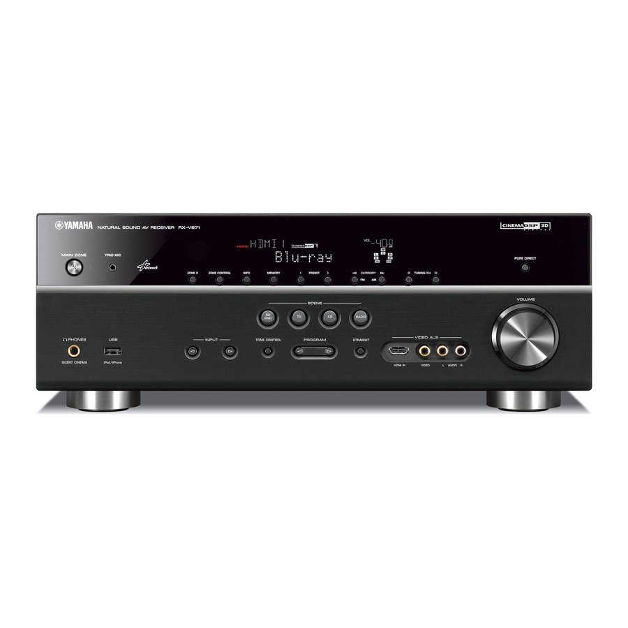
Yamaha RX-V671 Service Manual

Yamaha RX-V671 Service Manual

Av receiver
Hide thumbs Also See for RX-V671:

Advertisement

Note:
When the DIGITAL P.C.B. or IC83 on DIGITAL P.C.B. is replaced, the network function of this unit will not operate
properly without additional setting.
In such a case, report the serial number of this unit to the following e-mail address.
Yamaha Corporation will reply providing the setting procedure to make the network function of this unit operate
properly.
This manual has been provided for the use of authorized YAMAHA Retailers and their service personnel.
It has been assumed that basic service procedures inherent to the industry, and more specifi cally YAMAHA Products, are already known
and understood by the users, and have therefore not been restated.
WARNING:
IMPORTANT:
The data provided is believed to be accurate and applicable to the unit(s) indicated on the cover. The research, engineering, and service
departments of YAMAHA are continually striving to improve YAMAHA products. Modifications are, therefore, inevitable and
specifi cations are subject to change without notice or obligation to retrofi t. Should any discrepancy appear to exist, please contact the
distributor's Service Division.
WARNING:
IMPORTANT:
■ CONTENTS
TO SERVICE PERSONNEL ............................................2
FRONT PANELS .........................................................3-4
REAR PANELS ...........................................................5-8
REMOTE CONTROL PANELS .......................................9
SPECIFICATIONS ................................................... 10-15
INTERNAL VIEW .......................................................... 16
SERVICE PRECAUTIONS ............................................ 17
DISASSEMBLY PROCEDURES ............................. 18-23
UPDATING FIRMWARE ..........................................24-25
SELF-DIAGNOSTIC FUNCTION ............................26-67
CONFIRMATION OF
IDLING CURRENT OF AMP UNIT ....................68
1 0 1 2 1 4
RX-V671/HTR-6064/
E-mail: ycav-ysiss@gmx.yamaha.com
Failure to follow appropriate service and safety procedures when servicing this product may result in personal injury,
destruction of expensive components, and failure of the product to perform as specifi ed. For these reasons, we advise
all YAMAHA product owners that any service required should be performed by an authorized YAMAHA Retailer or
the appointed service representative.
The presentation or sale of this manual to any individual or fi rm does not constitute authorization, certifi cation or
recognition of any applicable technical capabilities, or establish a principle-agent relationship of any form.
Static discharges can destroy expensive components. Discharge any static electricity your body may have
accumulated by grounding yourself to the ground buss in the unit (heavy gauge black wires connect to this buss).
Turn the unit OFF during disassembly and part replacement. Recheck all work before you apply power to the unit.
Copyright © 2011
This manual is copyrighted by YAMAHA and may not be copied or
redistributed either in print or electronically without permission.
AV RECEIVER
RX-A710
SERVICE MANUAL

IMPORTANT NOTICE

DISPLAY DATA .......................................................69-70
IC DATA ...................................................................71-83
PIN CONNECTION DIAGRAMS .............................84-86
BLOCK DIAGRAMS ................................................87-91
PRINTED CIRCUIT BOARDS ............................... 92-125
SCHEMATIC DIAGRAMS ................................... 127-146
REPLACEMENT PARTS LIST ............................ 147-167
REMOTE CONTROL ........................................... 168-170
ADVANCED SETUP ............................................ 171-172
All rights reserved.
P.O.Box 1, Hamamatsu, Japan
'11.06

Advertisement

Table of Contents
loading

Summary of Contents for Yamaha RX-V671

  • Page 1: Table Of Contents

    This manual has been provided for the use of authorized YAMAHA Retailers and their service personnel. It has been assumed that basic service procedures inherent to the industry, and more specifi cally YAMAHA Products, are already known and understood by the users, and have therefore not been restated.
  • Page 2: To Service Personnel

    RX-V671/HTR-6064/RX-A710 ■ TO SERVICE PERSONNEL AC LEAKAGE WALL EQUIPMENT TESTER OR 1. Critical Components Information OUTLET UNDER TEST EQUIVALENT Components having special characteristics are marked must be replaced with parts having specifications equal to those originally installed. 2. Leakage Current Measurement (For 120V Models Only)
  • Page 3: Front Panels

    RX-V671/HTR-6064/RX-A710 ■ FRONT PANELS RX-V671 (U model) RX-V671 (C, R, T, A, B, G, F, L, S models) HTR-6064 (A, F models)
  • Page 4 RX-V671/HTR-6064/RX-A710 RX-A710 (U, C models) RX-A710 (A model)
  • Page 5: Rear Panels

    RX-V671/HTR-6064/RX-A710 ■ REAR PANELS RX-V671 (U model) RX-V671 (C model) RX-V671 (R, S models)
  • Page 6 RX-V671/HTR-6064/RX-A710 RX-V671 (T model) RX-V671 (A model) RX-V671 (B, G, F models)
  • Page 7 RX-V671/HTR-6064/RX-A710 RX-V671 (L model) HTR-6064 (A model) HTR-6064 (B, G, F models)
  • Page 8 RX-V671/HTR-6064/RX-A710 RX-A710 (U model) RX-A710 (C model) RX-A710 (A model)
  • Page 9: Remote Control Panels

    RX-V671/HTR-6064/RX-A710 ■ REMOTE CONTROL PANELS RAV436 RAV437 RAV438 (U model) (C model) (R, T, A, B, G, F, L, S models)
  • Page 10: Specifications

    RX-V671/HTR-6064/RX-A710 ■ SPECIFICATIONS ■ Audio Section Rated Output Power (Power Amp. Section) Total Harmonic Distortion (20 Hz to 20 kHz) – 1 channel driven – U, C models (50 W/8 ohms) AV5 etc. (PURE DIRECT) to FRONT SP OUT ......2.3 V (1 kHz, 0.9 % THD)
  • Page 11 ....435 x 171 x 366.6 mm (17-3/16" x 6-12/16" x 14-8/16") Weight This receiver supports network connections. [RX-V671/HTR-6064] ............... 10.52 kg (23.19 lbs.) Bluetooth is a registered trademark of the Bluetooth SIG and is used by [RX-A710] Yamaha in accordance with a license agreement................ 10.74 kg (23.68 lbs.)
  • Page 12 “x.v.Color” is a trademark of Sony Corporation. Windows is a registered trademark of Microsoft Corporation in the United “SILENT CINEMA” is a trademark of Yamaha Corporation. States and other countries. Windows XP, Windows Vista, Windows 7, Windows Media Audio, Windows...
  • Page 13 RX-V671/HTR-6064/RX-A710 • SELECT MENU Sound field parameters Category Program MOVIE THEATER Standard Spectacle Sci-Fi Adventure Drama Mono Movie ENTERTAINMENT Sports Action Game Roleplaying Game Music Video CLASSICAL Hall in Munich Hall in Vienna Chamber LIVE/CLUB Cellar Club The Roxy Theatre...
  • Page 14 RX-V671/HTR-6064/RX-A710 • SET MENU TABLE MAIN MENU SUB-MENU PARAMETER VALUE [INITIAL VALUE] Speaker Auto Measure Optimizes the speaker configuration automatically using YPAO. Setup Result Not Available Manual Power Amp Assign [Basic] / 7ch +1ZONE / 5ch BI-AMP Configuration Front Large / [Small] When “Subwoofer”...
  • Page 15 RX-V671/HTR-6064/RX-A710 MAIN MENU SUB-MENU PARAMETER VALUE [INITIAL VALUE] HDMI Setup HDMI Control [Off] / On TV Audio Input AV1 / AV2 / AV3 / [AV4] / AV5 / AV6 / AUDIO1 / AUDIO2 ARC (Audio Return Channel) Off / [On]...
  • Page 16: Internal View

    RX-V671/HTR-6064/RX-A710 ■ INTERNAL VIEW RX-V671/HTR-6064 Top view VIDEO (2) P.C.B. VIDEO (3) P.C.B. VIDEO (8) P.C.B. (R, S models) OPERATION (8) P.C.B. MAIN (2) P.C.B. DIGITAL (1) P.C.B. VIDEO (1) P.C.B. VIDEO (4) P.C.B. AM/FM TUNER VIDEO (5) P.C.B. (B, G, F models) VIDEO (10) P.C.B.
  • Page 17: Service Precautions

    RX-V671/HTR-6064/RX-A710 RX-A710 Top view VIDEO (2) P.C.B. VIDEO (3) P.C.B. OPERATION (8) P.C.B. MAIN (2) P.C.B. DIGITAL (1) P.C.B. VIDEO (1) P.C.B. VIDEO (4) P.C.B. AM/FM TUNER VIDEO (10) P.C.B. (A model) OPERATION (2) P.C.B. OPERATION (7) P.C.B. OPERATION (9) P.C.B. (U, C models) OPERATION (10) P.C.B.
  • Page 18: Disassembly Procedures

    RX-V671/HTR-6064/RX-A710 ■ DISASSEMBLY PROCEDURES RX-V671/HTR-6064 RX-V671/HTR-6064 (Remove parts in the order as numbered.) Disconnect the power cable from the AC outlet. 1. Removal of Top Cover a. Remove 4 screws ( ) and 5 screws ( ). (Fig. 1) b. Lift the rear of the top cover to remove it.
  • Page 19 RX-V671/HTR-6064/RX-A710 3. Removal of DIGITAL (1) P.C.B. 4. Removal of AMP Unit a. Remove 3 screws ( ) and 6 screws ( ). (Fig. 3) a. Remove screw ( ), 2 screws ( ) and 4 screws ( ). b. Remove 3 screws. ( ). (Fig. 2) (Fig.
  • Page 20 RX-V671/HTR-6064/RX-A710 When checking the P.C.B.s: • Follow the procedure below to place the P.C.B.s (with rear panel) upright. (Fig. 5) a. Remove the top cover. (Fig. 1) b. Remove screw ( ), 2 screws ( ) and 4 screws ( ). (Fig. 2) c.
  • Page 21 RX-V671/HTR-6064/RX-A710 RX-A710 RX-A710 (Remove parts in the order as numbered.) Disconnect the power cable from the AC outlet. 1. Removal of Top Cover a. Remove 4 screws ( ), screw ( ) and 5 screws ( ). (Fig. 1) b. Slide the top cover rearward to remove it. (Fig. 1) 2.
  • Page 22 RX-V671/HTR-6064/RX-A710 3. Removal of DIGITAL (1) P.C.B. 4. Removal of AMP Unit a. Remove 3 screws ( ) and 6 screws ( ). (Fig. 3) a. Remove screw ( ), 2 screws ( ) and 5 screws ( ). b. Remove 3 screws. ( ). (Fig. 2) (Fig.
  • Page 23 RX-V671/HTR-6064/RX-A710 When checking the P.C.B.s: • Follow the procedure below to place the P.C.B.s (with rear panel) upright. (Fig. 5) a. Remove the top cover. (Fig. 1) b. Remove screw ( ), 2 screws ( ) and 5 screws ( ). (Fig. 2) c.
  • Page 24: Updating Firmware

    USB storage device • Firmware RX-V671/HTR-6064/RX-A710: RXV671-xxxx.bin ● Preparation 1. Download the latest firmware from the specified download source to the folder of the PC. 2. Copy the latest firmware from the PC to the root folder of the USB storage device.
  • Page 25 RX-V671/HTR-6064/RX-A710 ● Operation Procedures 1. Insert the USB storage device to the USB port. (Fig. 1) 2. While pressing the “PURE DIRECT” key, connect the power cable to the AC outlet. (Fig. 1) "MAIN ZONE " key USB port "PURE DIRECT" key USB storage device Fig.
  • Page 26: Self-Diagnostic Function

    RX-V671/HTR-6064/RX-A710 ■ SELF-DIAGNOSTIC FUNCTION This unit has self-diagnostic functions that are intended for inspection, measurement and location of faulty point. There are 25 main menu items, each of which has sub-menu items. Listed in the table below are main menu items and sub-menu items.
  • Page 27 RX-V671/HTR-6064/RX-A710 Main menu Sub-menu Z: Zone system ZONE TEST (Not for service) (Not for service) (Not for service) (Not for service) (Not for service) (Not for service) AUDIO1 AUDIO2 V-AUX 10 PHONO R: Radio and satellite broadcasting system SIRIUS (U model)
  • Page 28 RX-V671/HTR-6064/RX-A710 Main menu Sub-menu HDMI INFORMATION HDMI MODEL NAME HDMI ID V: Video system ANALOG VIDEO CHECK ANALOG BYPASS DIGITAL BYPASS INVALID ITEM (Not for service) MUTE CHECK TEST PATTERN VIDEO IN DIGITAL VIDEO CHECK LOOPBACK TEST 1 LOOPBACK TEST 2...
  • Page 29 RX-V671/HTR-6064/RX-A710 Main menu Sub-menu S: System and version system FIRMWARE UPDATE F/W UPDATE (Not for service) SET INFORMATION MODEL DESTINATION DEBUG (Not for service) FACTORY PRESET PRESET INH/RSRV ROM VERSION/CHECKSUM SYSTEM VERSION MICROPROCESSOR VERSION MICROPROCESSOR CHECKSUM FLASH ROM VERSION FLASH ROM CHECKSUM...
  • Page 30 RX-V671/HTR-6064/RX-A710 ● Starting Self-Diagnostic Function While pressing the “TONE CONTROL” and “INFO” keys, press the “MAIN ZONE ” key to turn on the power. The self-diagnostic function mode is activated. Keys of this unit While pressing these keys, turn on the power.
  • Page 31 RX-V671/HTR-6064/RX-A710 ● Canceling Self-Diagnostic Function Before canceling self-diagnostic function, execute setting for “S3. FACTORY PRESET” menu. (Memory initialization inhibited or Memory initialized). In order to keep the user memory preserved, be sure to select PRESET INHIBIT (Memory initialization inhibited). Press the “MAIN ZONE ” key to turn off the power.
  • Page 32 RX-V671/HTR-6064/RX-A710 2-2. When the protection function worked due to abnormal DC output. AD conversion value when the protection function is working Cause: DC output of the power amplifier is abnormal. Supplementary information: The protection function worked due to a DC voltage appearing at the speaker terminal. A cause could be a defect in the amplifier.
  • Page 33 RX-V671/HTR-6064/RX-A710 2-4. When the protection function worked due to excessive heatsink temperature. AD conversion value when the protection function is working Cause: The temperature of the heatsink is excessive. Supplementary information: The protection function worked due to the temperature limit being exceeded. Causes could be poor ventilation or a defect related to the thermal sensor.
  • Page 34 RX-V671/HTR-6064/RX-A710 ● Operation procedure of Main menu and Sub-menu There are 25 main menu items, each of which has sub-menu items. Main menu selection Select the main menu using “SCENE TV” (forward) and “SCENE BD/DVD” (reverse) keys. Sub-menu selection Select the sub-menu using “SCENE RADIO” (forward) and “SCENE CD” (reverse) keys.
  • Page 35 RX-V671/HTR-6064/RX-A710 ● Details of Self-Diagnostic Function menu A1. DSP AUDIO This menu is used to check audio signal route via DSP. A1-1. DSP MARGIN The audio signal is output including the head margin via DSP. * When input source is stereo, signal is assigned as below.
  • Page 36 RX-V671/HTR-6064/RX-A710 A1-6. DSP FULL SURROUND BACK The audio signal is output to only SURROUND BACK L/R channels in digital full bit without including the head margin. A1-7. DSP FULL SUBWOOFER The audio signal is output to only SUBWOOFER channels in digital full bit without including the head margin.
  • Page 37 RX-V671/HTR-6064/RX-A710 A3. HDMI AUDIO This menu is used to check the route of audio signal input to HDMI IN/OUT. * Before check using “A3-3. ARC 1” menu, be sure to connect a TV monitor equipped with Audio Return Channel function to this unit in advance.
  • Page 38 RX-V671/HTR-6064/RX-A710 A4. SPEAKERS SET This menu is used to check the speaker output. A4-1. BI-AMP The FRONT L/R signal is distributed to SURROUND BACK/BI-AMP L/R terminal. A4-2. ZONE/TONE=MAX The audio signal is output with the tone control “BASS +10 dB” , “TREBLE +10 dB” .
  • Page 39 RX-V671/HTR-6064/RX-A710 INPUT: AV5 ANALOG SPEAKER OUT: 1 kHz, SUBWOOFER OUTPUT: 50 Hz SPEAKERS OUTPUT SUB- Sub-memu Input level Volume SURROUND SURROUND PRESENCE/ WOOFER FRONT L/R CENTER BACK L/R ZONE2 OUTPUT Both ch, A4-1. BI-AMP +6.5 dB +13.0 dBm +13.0 dBm +13.0 dBm...
  • Page 40 RX-V671/HTR-6064/RX-A710 A7. MANUAL TEST The built-in noise generator of DSP outputs the test noise or test tone through the channels specified by using the sub- menu. Test noise Test tone 30 Hz to 80 Hz 50 Hz for LFE pink noise...
  • Page 41 RX-V671/HTR-6064/RX-A710 A7-10. TEST FRONT PRESENCE R The test tone is output from FRONT PRESENCE R channel. A7-11. INVALID ITEM Not for service. A7-12. INVALID ITEM Not for service. A7-13. TEST LFE 1 The test tone is output from LFE 1 (SUBWOOFER) channel.
  • Page 42 RX-V671/HTR-6064/RX-A710 D1. FL CHECK This menu is used to check the FL display. FL display D1-1. INITIAL DISPLAY D1-2. ALL SEGMENT OFF D1-3. ALL SEGMENT ON * After check, change to next sub-menu at once. D1-4. CHECK PATTERN 1 Example Lighting on segments in lattice.
  • Page 43 RX-V671/HTR-6064/RX-A710 Z1. ZONE TEST This menu is used to check audio signal route to ZONE 2 PRE OUT. Z1-1. AV1 Not for service. Z1-2. AV2 Not for service. Z1-3. AV3 Not for service. Z1-4. AV4 Not for service. Z1-5. AV5 Not for service.
  • Page 44 RX-V671/HTR-6064/RX-A710 R1. SIRIUS (U model) The SIRIUS information are displayed. R1-1. SIRIUS Connection of the SIRIUS antenna module is checked. OK : Normal NG : Abnormal : No connected R1-2. SR The connection information of the SIRIUS antenna module is displayed.
  • Page 45 RX-V671/HTR-6064/RX-A710 U1. iPod This menu is used to check the DOCK jack/iPod authentication IC without connecting the iPod itself. U1-1. DOCK CHECK With the power turned off, short the pins of the DOCK jack as shown in the figure below.
  • Page 46 RX-V671/HTR-6064/RX-A710 U2. USB This menu is used to check audio signal route of USB. U2-1. BF (NETWORK microprocessor) TEST 1kHz The built-in noise generator of BF (IC901 on DIGITAL P.C.B.) outputs the 1 kHz test tone. Output: From Front L/R, Center, Surround L/R, Surround Back L/R U2-2.
  • Page 47 RX-V671/HTR-6064/RX-A710 N1. NETWORK This menu is used to check signal route of NETWORK. Connect between NETWORK port of this unit and LAN port of broadband with a network cable. When the network condition varies while sub-menu is displayed (e.g., the network is deactivated once), the correct result will not be displayed.
  • Page 48 RX-V671/HTR-6064/RX-A710 N1-5. EXT TEST Transmission/reception of the NETWORK connector is checked. With the power turned off, short the pins of the NETWORK port as shown in the figure below. Start up the self-diagnostic function and select this menu. Note) Be sure to return the shorted pins to their original condition after executing this test.
  • Page 49 RX-V671/HTR-6064/RX-A710 C1-3. BUS FPGA Communication and bus line connection between microprocessor (IC81) and FPGA (IC51) are checked. : No error detected NG : An error is detected C1-4. I2C The I2C (Inter integrated route) bus line connection is checked. : No error detected : An error is detected –...
  • Page 50 RX-V671/HTR-6064/RX-A710 C1-7. BUS DSP1 Communication and bus line connection between microprocessor (IC81) and DSP1 (IC921) are checked. : No error detected NG : An error is detected C1-8. EEPROM Reading EEPROM (IC83) is checked. : No error detected NG : An error is detected C1-9.
  • Page 51 RX-V671/HTR-6064/RX-A710 C1-12. I2C EEPROM Communication and bus line connection between microprocessor (IC81) and EEPROM (IC83) are checked. OK: No error detected NG: An error is detected Checking C1-13. BUS RAM Communication and bus line connection between RAM (IC902, IC903) and BF (NETWORK microprocessor, IC901) are checked.
  • Page 52 RX-V671/HTR-6064/RX-A710 C2. INVALID ITEM Not for service. C3. HDMI INFORMATION This menu is used to display information about HDMI. C3-1. HDMI MODEL NAME The model name of this unit written in HDMI module is displayed. RX-V671 HTR-6064 RX-A710 C3-2. HDMI PRODUCT ID The product ID of this unit written in HDMI module is displayed.
  • Page 53 RX-V671/HTR-6064/RX-A710 V1. ANALOG VIDEO CHECK This menu is used to check the analog video signal route. V1-1. ANALOG BYPASS The video signal is converted and output as shown below. ANALOG BYPASS HDMI IN HDMI OUT DIGITAL DIGITAL DIGITAL IC61 IC51...
  • Page 54 RX-V671/HTR-6064/RX-A710 V1-4. MUTE CHECK The video signal is muted. MUTE CHECK HDMI IN HDMI OUT DIGITAL DIGITAL DIGITAL IC61 IC51 HDMI HDMI FPGA Receiver Transmitter DIGITAL DIGITAL Component In Component Out IC21 IC22 MUTE VIDEO VIDEO VDEC_N_RST VIDEO VIDEO Decoder...
  • Page 55 RX-V671/HTR-6064/RX-A710 V2. DIGITAL VIDEO CHECK This menu is used to check the digital video signal route. V2-1. LOOPBACK TEST 1 Execute the test for all HDMI IN jacks by repeating the procedure below. 1. Select sub-menu other than V2-1. 2. Connect between any of the HDMI IN jacks and HDMI OUT jack with an HDMI cable.
  • Page 56 RX-V671/HTR-6064/RX-A710 V2-2. LOOPBACK TEST 2 Execute the test for all HDMI IN jacks by repeating the procedure below. 1. Select sub-menu other than V2-2. 2. Connect between any of the HDMI IN jacks and HDMI OUT jack with an HDMI cable.
  • Page 57 RX-V671/HTR-6064/RX-A710 V2-4. HDMI REPEAT * Before check using sub-menu V2-4, disconnect the HDMI cable connected between HDMI OUT jack and HDMI IN jack of this unit in advance. The video/audio signals input to HDMI IN jack are output to HDMI OUT jack.
  • Page 58 RX-V671/HTR-6064/RX-A710 V2-6. DIGITAL Y/C (B, G, F models) The s-video (Y, C) signal is converted and output as shown below. HDMI CB31 CB61 HDMI HDMI HDMI HDMI HDMI HDMI HDMI Front IC31 HDMI EQ HDMI SW HDMI SW HDMI TX...
  • Page 59 RX-V671/HTR-6064/RX-A710 V2-8. DIGITAL COMPONENT SC The component video (Y, Cb, Cr) signal is converted and output as shown below. HDMI video output up-scaling: 480i/p, 576i/p only => 1080p HDMI CB31 CB61 HDMI HDMI HDMI HDMI HDMI HDMI HDMI Front IC31...
  • Page 60 RX-V671/HTR-6064/RX-A710 V3. TEST PATTERN The video signal is output to HDMI OUT jack with its resolution converted as shown below. HDMI CB31 CB61 HDMI HDMI HDMI HDMI HDMI HDMI HDMI Front IC31 HDMI EQ HDMI SW HDMI SW HDMI TX...
  • Page 61 RX-V671/HTR-6064/RX-A710 P1. SYSTEM MONITOR This menu is used to display the A/D conversion value of the microprocessor which detects panel keys and protection functions by using the sub-menu. When “P1-7. KEY1/KEY2” sub-menu is selected, keys become non-operable due to detection of the values of all keys.
  • Page 62 RX-V671/HTR-6064/RX-A710 P1-4. INVALID ITEM Not for service. P1-5. OUTPUT LEVEL Output level of speaker output is detected. The voltage at 165 pin (AMP_OLV) of IC89 is displayed. (Reference voltage: 3.3 V=255) P1-6. LIMITER CONTROL Power limitter control is detected. The voltage at 4 pin (AMP_LMT) of IC81 is displayed.
  • Page 63 RX-V671/HTR-6064/RX-A710 P1-7. KEY1/KEY2 Panel key is detected. When the A/D conversion value of the panel key becomes out of the specified range, normal operation will not be available. In that case, check the constant of voltage dividing resistor, solder condition, etc. Refer to table.
  • Page 64 Not for service. S2. SET INFORMATION The model name and destination of this unit are displayed. S2-1. MODEL The model name of this unit is displayed. Not for service. Model name V671 : RX-V671 6064 : HTR-6064 A710 : RX-A710...
  • Page 65 RX-V671/HTR-6064/RX-A710 S2-2. DESTINATION The destination of this unit is displayed. A/D conversion value Destination Destination R, S B, G, F A/D conversion value 0 − 12 13 − 39 40 − 67 68 − 92 93 − 115 116 − 140 141 −...
  • Page 66 RX-V671/HTR-6064/RX-A710 S4. ROM VERSION/CHECKSUM The firmware version and checksum values are displayed. The checksum is obtained by adding the data at every 8-bit and expressing the result as a 4-figure hexadecimal notation. Numeric values in the figure are given as reference only.
  • Page 67 RX-V671/HTR-6064/RX-A710 S4-11. INVALID ITEM Not for service. S4-12. GUI VERSION The firmware version of GUI data is displayed. S4-13. FPGA GUI VERSION The firmware version of GUI section in FPGA (IC51 on DIGITAL P.C.B.) is displayed. S4-14. FPGA IP VERSION The firmware version of video processor section in FPGA (IC51 on DIGITAL P.C.B.) is displayed.
  • Page 68: Confirmation Of Idling Current Of Amp Unit

    RX-V671/HTR-6064/RX-A710 ■ CONFIRMATION OF IDLING CURRENT OF AMP UNIT ● Right after power is turned on, confirm that the voltage across the terminals of R1152 (SURROUND BACK Rch), R1154 (SURROUND Rch), R1150 (FRONT Rch), R1148 (CENTER), R1149 (FRONT Lch), R1153 (SURROUND Lch), R1151 (SURROUND BACK Lch) are between 0.1 mV and 10.0 mV.
  • Page 69: Display Data

    RX-V671/HTR-6064/RX-A710 ■ DISPLAY DATA ● V4001 : HNA-18MM03T (OPERATION P.C.B.) PATTERN AREA ● PIN CONNECTION Pin No. 68 67 Connection F2 F2 29 28 Pin No. Connection Note : 1) F1, F2 ..Filament pin 2) 1G–18G ..Grid pin 3) P1–P36 ..
  • Page 70 RX-V671/HTR-6064/RX-A710 ● ANODE CONNECTION 1G–14G –...
  • Page 71: Ic Data

    RX-V671/HTR-6064/RX-A710 ■ IC DATA IC81: R5F6416MADFE (DIGITAL P.C.B.) Microprocessor * No replacement part available. Port P0 Port P1 Port P2 Port P3 Port P4 Port P5 Port P6 Port P7 Peripheral functions A/D converter: Clock generator: Timer: 10 bits × 1 circuit 4 circuits Timer A16 bits ×...
  • Page 72 RX-V671/HTR-6064/RX-A710 Related Power Supply Port Name Function Name Detail of Function Logic Logic SRXD4/SDA4/TXD4/ TUN_SDA Data Tuner I2C data ANEX1/P9_6 HDR_MOSI Data HD Radio transmission data (U model) CLK4/ANEX0/P9_5 VOL1_SCK Clock VOL1 (R2A15220FP #1) communication clock N_CTS4/N_N_RTS4/ N_SS4/TB4IN/DA1/ VOL_MOSI Data...
  • Page 73 RX-V671/HTR-6064/RX-A710 Related Power Supply Port Name Function Name Detail of Function Logic Logic IIO1_0/TXD8/N_SS2/ N_RTS2/N_CTS2/V/ DK1_N_IPDET L act Dock iPod detect TA1IN/P7_3 CLK2/V/TA1OUT/ SR_PON H act SIRIUS power supply control P7_2 MSCL/IEIN/ISRXD2/ OUTC2_2/IIO1_7/ SR_MISO Data SIRIUS reception data STXD2/SCL2/RXD2/ TA0IN/TB5IN/P7_1...
  • Page 74 RX-V671/HTR-6064/RX-A710 Related Power Supply Port Name Function Name Detail of Function Logic Logic 79 P19_3 DK1_AP L act iPod accessory power 80 P17_3 DK1_PON H act Dock power supply 81 P17_2 UAW_PON H act UAW power supply control 82 P17_1...
  • Page 75 RX-V671/HTR-6064/RX-A710 Related Power Supply Port Name Function Name Detail of Function Logic Logic A4/[A4/D4]/AN2_4/ P2_4/N_CTS10/N_ A[4] External bus RTS10 A3/[A3/D3]/AN2_3/ A[3] External bus P2_3/TXD9 A2/[A2/D2]/AN2_2/ A[2] External bus P2_2/RXD9 A1/[A1/D1]/BC2/ [BC2/D1]/AN2_1/ A[1] External bus P2_1/CLK9 A0/[A0/D0]/BC0/ [BC0/D0]/AN2_0/ A[0] External bus...
  • Page 76 RX-V671/HTR-6064/RX-A710 Related Power Supply Port Name Function Name Detail of Function Logic Logic IIO0_4/TXD6/SDA6/ SRXD6/AN15_4/ EX1_N_RST L act Expansion IO 1 reset P15_4 IIO0_3/N_RTS7/N_ AD_SEL_A AD select A CTS7/AN15_3/P15_3 IIO0_2/RXD7/ AD_SEL_B AD select B AN15_2/P15_2 IIO0_1/CLK7/ IR_OUT Data Remote control cord output...
  • Page 77 RX-V671/HTR-6064/RX-A710 • Microprocessor extended port IC84, 85: TC74VHC273FT (DIGITAL P.C.B.) Octal D-type flip-flop with clear 20 V CC CK Q CK Q CK Q CK Q CK Q CK Q CK Q CK Q Inputs Output Function Clear − −...
  • Page 78 RX-V671/HTR-6064/RX-A710 IC89: SN74LV4051APWR (DIGITAL P.C.B.) 8-channel analog multiplexers/demultiplexers INPUTS CHANNEL None Related Power Supply Port Name Function Name Detail of Function Logic Logic AD selector 1 (AD1_COM signal is input into AN_5 of R32C) PS2_PRT Power supply protection 2 PS1_PRT...
  • Page 79 RX-V671/HTR-6064/RX-A710 IC308: LC709004A-TLM-E (VIDEO P.C.B.) I/O-expander for microcontroller Serial/parallel converter/shift register DOUT CLK# RES# I/O control/output register port 0 I/O buffer port 1 I/O buffer Related Power Supply Port Name Function Name Detail of Function Logic Logic VID_N_MMT L act...
  • Page 80 RX-V671/HTR-6064/RX-A710 IC901: ADSST-DR-11Z (DIGITAL P.C.B.) Network microprocessor * No replacement part available. OTP MEMORY WATCHDOG TIMER VOLTAGE REGULATOR JTAG TEST AND EMULATION COUNTER PERIPHERAL SPORT0 ACCESS BUS SPORT1 INTERRUPT GPIO UART1 CONTROLLER PORT F UART0 L1 INSTRUCTION L1 DATA GPIO...
  • Page 81 RX-V671/HTR-6064/RX-A710 Pin No. Port Name Function Name Detail of Function Logic PH5/ND_D5/ETXD0/HOST_D5 RMII_TXD0 Data PHY: RMII TXD0 PH6/ND_D6/ERXD0/HOST_D6 RMII_RXD0 Data PHY: RMII RXD0 PH7/ND_D7/ETXD1/HOST_D7 RMII_TXD1 Data PHY: RMII TXD1 PH9/%SPISEL5%/ETXD2/HOST_ SPI_N_ON Data R32C to/from Blackfin SPI_I/F switch control (L: active, H: off)
  • Page 82 RX-V671/HTR-6064/RX-A710 Pin No. Port Name Function Name Detail of Function Logic VDDINT /AMS0 EXT_WAKE0 Data Wake up indication 0 PG9/TMR5/RSCLK0A/TACI5 NCPU_PIC_MISO L act Buffer overflow flag of FPGA PG10/TMR6/TSCLK0A/TACI6 MT_DAC_Z H act ZONE DAC mute VDDEXT VDDEXT VDDINT /AMS1 CLKOUT...
  • Page 83 RX-V671/HTR-6064/RX-A710 Pin No. Port Name Function Name Detail of Function Logic BF_JTAG_TDI Data ICE Debug TDI Inter- PG0/HWAIT BF_JTAG_N_INT rupt /SMS BF_N_SMS L act SDRAM chip select VDDOTP BF_JTAG_TDO Data ICE Debug TDO /EMU BF_JTAG_N_EMU Data ICE Debug /EMU /SRAS...
  • Page 84: Pin Connection Diagrams

    RX-V671/HTR-6064/RX-A710 ■ PIN CONNECTION DIAGRAMS • ICs ADV7172KST ADV7181CBSTZ BD9329AEFJ-E2 D70YE101BRFP266 SiI9233ACTU EP2C8F256C8N FHP3350IM14X 5V49EE503-027NLGI8 KIA7805API KIA7912PI KSZ8051RNL LA73050-TLM-E LC709004A-TLM-E LC4032ZE-7TN48C LM19CIZ/LF LM833MX M12L128168A-5TG2T M12L64164A-5TG M66003-0131FP-R MFI341S2164 MX29LV160DBTI-70G MX29LV640EBTI-70G NT5SV32M8CS-6K NJM2068MD-TE2 NJM2388F05 NJM2505A NJM2888F05 1. V 2. V 3. GND 4.
  • Page 85 RX-V671/HTR-6064/RX-A710 PCM9210PTR R1172H121D-T1-F R1172H501D-T1-F R1172N501D-TR-F R1172S331D-E2-F R1EX24128BTAS0A R1EX25512ATA00A 1: CE 2: GND 3: NC 4: V 5: V R2A15220FP R5F6416MADFE RP130Q121D-TR-F SiI9134CTU RP130Q181D-TR-F RP130Q331D-TR-F RP130Q501D-TR-F SiI9185ACTU SN74LV4051APWR SN74LVC1G17DCKR STR2A153 TC74HC4051AFEL TC74HC4053AF TC74LCX245FT TC74VHC157FT TC74VHC273FT (EL,K) TC74VHC86FT (EL) TC74VHCU04FT TC7SET08FU TC7SH08FU...
  • Page 86 RX-V671/HTR-6064/RX-A710 • Diodes 1SS355 D1FL20U-5063 D6SBN20 DBL155G HZU4.3B3 TRF-E MTZJ2.4B 1SS355VMTE-17 MTZJ5.1C MTZJ6.8C Anode MTZJ13B Anode Anode Anode – – Cathode Cathode Cathode + AC Cathode RB215T-90 RB501V-40 RLZ7.5B 7.5V RS203M-B-C-J80 RS603M-B-C-J80 SARS05 UDZS12B 12V RB521S-30 UDZS36B 36V UDZS5.1B 5.1V...
  • Page 87: Block Diagrams

    RX-V671/HTR-6064/RX-A710 ■ BLOCK DIAGRAMS AUDIO Section Block Diagram → OPERATION → DIGITAL → VIDEO → MAIN VIDEO →...
  • Page 88 RX-V671/HTR-6064/RX-A710 DIGITAL P.C.B. Section Block Diagram Front USB HDMI REAR IN Front HDMI HDMI OUT HDMI SW Rear USB NETWORK TMDS261B DOCK2 DOCK1 (for WiFi) OUT1 HDMI DK1_AUDIO DK1_VIDEO R32C R32C HDMI HDMI UART2 UART10 DK2_AUDIO Switcher Switcher IC61 IC906...
  • Page 89 RX-V671/HTR-6064/RX-A710 NET/USB Section Block Diagram Front USB NERWORK → DIGITAL SCHEMATIC DIAGRAM Bus Power 1A USB_24M PHY_25M IC909 IC910 EEPROM IC906 Apple 128Kbit Ethernet PHY Coprocessor R1EX24128ASAS0A KSZ8051RNL High Side MFI341S2164 Switch VOUT IC908 2SC4081 Clock IC IDT5V49EE903NLG BF_I2C_SCL SDAT...
  • Page 90 RX-V671/HTR-6064/RX-A710 VIDEO Section Block Diagram → VIDEO → DIGITAL...
  • Page 91 RX-V671/HTR-6064/RX-A710 Power Supply Section Block Diagram → → VIDEO DIGITAL IC65 IC493 IC945 AC IN IC494 IC946 IC97 Microprocessor IC98 IC26 IC99 IC27 IC929 IC930 IC481 OPERATION → IC54...
  • Page 92: Printed Circuit Boards

    RX-V671/HTR-6064/RX-A710 Ref no. Location Ref no. Location IC34 IC903 RX-V671/HTR-6064 RX-A710 IC51 IC904 ■ PRINTED CIRCUIT BOARDS IC52 IC906 IC53 IC907 IC54 IC908 IC61 IC916 DIGITAL (1) IC63 IC921 (Side A) IC64 IC923 IC68 IC924 IC81 IC926 No replacement part available.
  • Page 93 RX-V671/HTR-6064/RX-A710 RX-V671/HTR-6064 RX-A710 DIGITAL (1) (Side B) No replacement part available. • Semiconductor Location Ref no. Location Ref no. Location D201 D202 D351 IC917 IC915 D360 D361 D362 D605 D801 Q201 Q203 IC65 IC80 Q351 IC909 IC83 Q804 IC91 Q805...
  • Page 94 RX-V671/HTR-6064/RX-A710 RX-V671/HTR-6064 OPERATION (1) (Side A) DIGITAL (1) (CB81) FDL_N_RST FDL_N_CS FDL_SCK FDL_MOSI MIC_N_DET REM_IN RMS_OUT DGND DGND PRV2 DGND PSW_DET KEY1 KEY2 VDL_RA VDL_RB PD_LED FL_PON Remote control sensor +3.3M STBY_LED +5.5 +5.5 DGND DGND -12V OPERATION (2) +12V...
  • Page 95 RX-V671/HTR-6064/RX-A710 RX-V671/HTR-6064 OPERATION (1) (Side B) IC401 • Semiconductor Location Ref no. Location Ref no. Location Ref no. Location Ref no. Location D4001 D4083 IC401 Q4008 D4002 D4084 IC481 Q4009 D4085 Q4001 Q4012 D4006 D4007 D4086 Q4002 Q4081 D4010 D4091...
  • Page 96 RX-V671/HTR-6064/RX-A710 RX-V671/HTR-6064 DIGITAL (1) DIGITAL (1) DIGITAL (1) (CB945) (CB944) (CB943) OPERATION (2) (Side A) OPERATION (1) (CB402) CB458 CB461 CB460 CB459 U model SIRIUS C, R, T, A, B, G, F, L, S models IC457 R, T, A, B, G, F, L, S models...
  • Page 97 RX-V671/HTR-6064/RX-A710 RX-V671/HTR-6064 OPERATION (2) (Side B) IC456 U model IC453 IC454 IC452 IC451 • Semiconductor Location Ref no. Location D4203 D4204 IC458 D4205 IC451 IC452 IC453 IC454 IC455 IC456 IC458 IC459...
  • Page 98 RX-V671/HTR-6064/RX-A710 RX-V671/HTR-6064 OPERATION (3) OPERATION (4) (Side A) (Side A) PHONES SILENT CINEMA to chassis W4401 JK471 HDMI Through/ iPod Change indicator JK472 YPAO MIC HP_N_DET CB473 MAIN ZONE VIDEO (1) (W3401) OPERATION (1) (CB407) • Semiconductor Location Ref no. Location...
  • Page 99 RX-V671/HTR-6064/RX-A710 RX-V671/HTR-6064 OPERATION (3) OPERATION (4) (Side B) (Side B) • Semiconductor Location Ref no. Location D4411 D4412 D4421 D4422 D4423 OPERATION (5) OPERATION (6) (Side B) (Side B) IC471 Q4001 Q4401 Q4402...
  • Page 100 RX-V671/HTR-6064/RX-A710 RX-V671/HTR-6064 OPERATION (7) OPERATION (8) OPERATION (9) (Side A) (Side A) (Side A) U, C models CB463 ZONE 2/ CB491 PRESENCE VIDEO (1) (CB347) DIGITAL (1) (CB83) OPERATION (10) OPERATION (11) (Side A) (Side A) R, T, A, B, G, F, L, S models...
  • Page 101 RX-V671/HTR-6064/RX-A710 RX-V671/HTR-6064 OPERATION (7) OPERATION (8) OPERATION (9) (Side B) (Side B) (Side B) U, C models • Semiconductor Location Ref no. Location D4303 D4901 D4902 D4903 Q4301 Q4302 OPERATION (10) OPERATION (11) (Side B) (Side B) R, T, A, B, G, F, L, S models...
  • Page 102 RX-V671/HTR-6064/RX-A710 RX-A710 OPERATION (1) (Side A) DIGITAL (1) (CB81) OPERATION (5) FDL_N_RST FDL_N_CS (CB473) FDL_SCK FDL_MOSI MIC_N_DET REM_IN RMS_OUT MASW PURE DIRECT DGND ISEL_RA DGND ISEL_RB indicator PRV2 Remote control +3.3M DGND STBY_LED PSW_DET KEY1 sensor KEY2 VDL_RA VDL_RB PD_LED FL_PON +3.3M...
  • Page 103 RX-V671/HTR-6064/RX-A710 RX-A710 OPERATION (1) (Side B) IC401 16 17 OPERATION (4) (Side B) OPERATION (12) (Side B) • Semiconductor Location Ref no. Location Ref no. Location Ref no. Location D4086 Q4007 D4003 D4004 IC401 Q4008 D4007 IC481 Q4009 IC471 D4008...
  • Page 104 RX-V671/HTR-6064/RX-A710 RX-A710 DIGITAL (1) DIGITAL (1) DIGITAL (1) (CB945) (CB944) (CB943) OPERATION (2) (Side A) OPERATION (1) (CB402) CB458 CB461 CB460 CB459 U model SIRIUS C, A models IC457 A model -12V +12V CB455 VIDEO (10) (CB383) (A model) VIDEO (1)
  • Page 105 RX-V671/HTR-6064/RX-A710 RX-A710 OPERATION (2) (Side B) IC455 IC459 IC456 U model IC453 IC452 IC454 IC451 IC458 • Semiconductor Location Ref no. Location D4203 D4204 D4205 IC451 IC452 IC453 IC454 IC455 IC456 IC458 IC459...
  • Page 106 RX-V671/HTR-6064/RX-A710 RX-A710 OPERATION (3) OPERATION (5) (Side A) (Side A) POWER indicator • Semiconductor Location MAIN ZONE Ref no. Location CB473 D4407 HP_N_DET PHONES SILENT CINEMA OPERATION (1) VIDEO (1) (CB404) (W3401) OPERATION (7) (Side A) OPERATION (6) (Side A)
  • Page 107 RX-V671/HTR-6064/RX-A710 RX-A710 OPERATION (3) OPERATION (5) (Side B) (Side B) • Semiconductor Location Ref no. Location D4402 D4404 Q4401 OPERATION (7) (Side B) OPERATION (6) (Side B)
  • Page 108 RX-V671/HTR-6064/RX-A710 RX-A710 OPERATION (8) OPERATION (9) (Side A) (Side A) U, C models CB463 +3.3S ZONE 2/ PRESENCE VIDEO (1) DIGITAL (1) (CB347) (CB83) OPERATION (10) OPERATION (11) (Side A) (Side A) A model DIGITAL (1) (CB83) CB446 iPod/iPhone +3.3S...
  • Page 109 RX-V671/HTR-6064/RX-A710 RX-A710 OPERATION (8) OPERATION (9) (Side B) (Side B) U, C models • Semiconductor Location Ref no. Location D4303 D4901 D4902 D4903 Q4301 Q4302 OPERATION (10) OPERATION (11) (Side B) (Side B) A model...
  • Page 110 RX-V671/HTR-6064/RX-A710 RX-V671/HTR-6064 RX-A710 MAIN (1) (Side A) AUDIO1 AUDIO2 AUDIO ZONE2 SUBWOOFER 5 k-ohms OPTICAL COAXIAL COAXIAL OPTICAL (CD) (TV) 10 W 5 k-ohms 5 k-ohms 5 k-ohms 10 W 10 W 10 W OPERATION (2) (CB451) PJ159 +5DSP DGND...
  • Page 111 RX-V671/HTR-6064/RX-A710 RX-V671/HTR-6064 RX-A710 MAIN (1) (Side B) IC152 IC154 51 50 • Semiconductor Location Ref no. Location Ref no. Location D1001 Q1002 100 1 D1002 Q1003 Q1004 D1003 D1004 Q1005 D1005 Q1006 D1006 Q1007 D1007 Q1008 D1008 Q1009 D1009 Q1010...
  • Page 112 RX-V671/HTR-6064/RX-A710 RX-V671/HTR-6064 RX-A710 MAIN (2) MAIN (6) (Side A) (Side A) MAIN (1) MAIN (1) (CB101) (W101A)(W102A)(W103A)(W104A)(W105A) CB102 W102B W104B W101B W105B W103B POWER TRANSFORMER...
  • Page 113 RX-V671/HTR-6064/RX-A710 RX-V671/HTR-6064 RX-A710 MAIN (2) MAIN (6) (Side B) (Side B)
  • Page 114 RX-V671/HTR-6064/RX-A710 RX-V671/HTR-6064 VIDEO (1) (Side A) SPEAKERS FRONT CENTER SURROUND R SURROUND BACK/ BI-AMP COMPONENT VIDEO VIDEO MONITOR OUT TRIGGER COMPONENT VIDEO VIDEO JK321 CB301 CB342 CB343 W3401 CB347 CB340 CB346 CB344 CB303 OPERATION (8) MAIN (1) MAIN (1) (CB463)
  • Page 115 RX-V671/HTR-6064/RX-A710 RX-V671/HTR-6064 VIDEO (1) (Side B) IC307 IC305 IC306 IC308 IC301 IC302 IC310 IC303 • Semiconductor Location Ref no. Location Ref no. Location D3310 IC310 D3350 Q3001 D3403 Q3306 D3404 Q3405 D3405 Q3406 D3406 Q3407 D3407 Q3408 Q3409 IC301 IC302...
  • Page 116 RX-V671/HTR-6064/RX-A710 RX-V671/HTR-6064 VIDEO (2) VIDEO (3) (Side A) (Side A) VIDEO (9) VIDEO (6) (W3805A)(W3805B) (W3701B)(W3702B) (R, S models) (U, C, T, A, B, G, F, L models) W3701A W3702A AC IN CB377 W3703 CB375 CB376 DIGITAL (1) (CB947) DIGITAL (1) (CB948) •...
  • Page 117 RX-V671/HTR-6064/RX-A710 RX-V671/HTR-6064 VIDEO (2) VIDEO (3) (Side B) (Side B) • Semiconductor Location Ref no. Location D3702 D3703 D3706 D3707 D3708 D3709 D3710 D3711 D3712 D3713 D3714 D3715 Q3701 Q3702 Q3703...
  • Page 118 RX-V671/HTR-6064/RX-A710 RX-V671/HTR-6064 VIDEO (4) VIDEO (5) VIDEO (6) VIDEO (7) (Side A) (Side A) (Side A) (Side A) B, G, F models U, C, T, A, B, G, F, L models S VIDEO REMOTE W3701B JK391 VIDEO (1) (CB331) JK362...
  • Page 119 RX-V671/HTR-6064/RX-A710 RX-V671/HTR-6064 VIDEO (4) VIDEO (5) VIDEO (6) VIDEO (7) (Side B) (Side A) (Side B) (Side B) B, G, F models U, C, T, A, B, G, F, L models • Semiconductor Location Ref no. Location D3601 D3602 D3801...
  • Page 120 RX-V671/HTR-6064/RX-A710 RX-A710 VIDEO (1) (Side A) SPEAKERS FRONT CENTER SURROUND R SURROUND BACK/ BI-AMP COMPONENT VIDEO VIDEO MONITOR OUT TRIGGER COMPONENT VIDEO VIDEO JK321 CB301 CB342 CB343 W3401 CB347 CB340 CB346 CB344 CB303 OPERATION (8) (CB463) MAIN (1) MAIN (1)
  • Page 121 RX-V671/HTR-6064/RX-A710 RX-A710 VIDEO (1) (Side B) IC307 IC305 IC306 IC308 IC301 IC302 IC310 IC303 • Semiconductor Location Ref no. Location Ref no. Location D3310 IC310 D3403 Q3001 Q3306 D3404 D3405 Q3405 D3406 Q3406 D3407 Q3407 IC301 Q3408 IC302 Q3409 IC303...
  • Page 122 RX-V671/HTR-6064/RX-A710 RX-A710 VIDEO (2) VIDEO (3) (Side A) (Side A) VIDEO (6) (W3701B)(W3702B) (U, C models) W3701A W3702A CB377 W3703 CB375 AC IN CB376 DIGITAL (1) (CB947) DIGITAL (1) (CB948) • Semiconductor Location Ref no. Location D3701 Notes) D3704 Safety measures IC371 •...
  • Page 123 RX-V671/HTR-6064/RX-A710 RX-A710 VIDEO (2) VIDEO (3) (Side B) (Side B) • Semiconductor Location Ref no. Location D3702 D3703 D3706 D3707 D3708 D3709 D3710 D3711 D3712 D3713 D3714 D3715 Q3701 Q3702 Q3703...
  • Page 124 RX-V671/HTR-6064/RX-A710 RX-A710 VIDEO (4) VIDEO (6) VIDEO (7) (Side A) (Side A) (Side A) U, C models REMOTE W3701B VIDEO (1) (CB331) JK362 JK361 POWER TRANSFORMER CB334 W3601 DIGITAL (1) W3702B (CB82) VIDEO (2) (W3701A)(W3702A) POWER TRANSFORMER VIDEO (10) (Side A)
  • Page 125 RX-V671/HTR-6064/RX-A710 RX-A710 VIDEO (4) VIDEO (6) VIDEO (7) (Side B) (Side B) (Side B) U, C models VIDEO (10) (Side B) A model • Semiconductor Location Ref no. Location D3601 D3602 IC381 D3801 D3802 IC381...
  • Page 126: Schematic Diagrams

    RX-V671/HTR-6064/RX-A710 SCHEMATIC DIAGRAMS DIGITAL 1/8 Page 128 HDMI 5 HDMI 4 HDMI 3 HDMI 2 HDMI 1 to DIGITAL (2)_CB32 (BD/DVD) CB10 HDMI SWITCHER HDMI SWITCHER to DIGITAL 4/8 to DIGITAL 3/8 HDMI RECEIVER to DIGITAL 5/8 DIGITAL (1) No replacement part available.
  • Page 127 RX-V671/HTR-6064/RX-A710 DIGITAL 2/8 Page 141 RX-V671/HTR-6064 Page 143 to VIDEO (1)_CB303 VIDEO AUX to VIDEO (5)_CB391 HDMI IN (B, G, F models) Page 144 RX-A710 CB31 to VIDEO (1)_CB303 CB22 DIGITAL (1) DIGITAL (2) IC31: TMDS141RHAR HDMI switch IC27 VSADJ...
  • Page 128 RX-V671/HTR-6064/RX-A710 DIGITAL 3/8 to DIGITAL 4/8 to DIGITAL 1/8 No replacement part available. No replacement part available. to DIGITAL 5/8 IC51 IC51 IC51 FPGA FPGA FPGA to DIGITAL 2/8 IC53 IC54 IC53 No replacement part available. SDRAM 128 Mbit IC52...
  • Page 129 RX-V671/HTR-6064/RX-A710 DIGITAL 4/8 HDMI OUT CB61 CB62 IC68 IC67 IC66 IC65 to DIGITAL 1/8 to DIGITAL 5/8 HDMI TRANSMITTER IC61 IC62 IC64 to DIGITAL 8/8 IC63 IC61: SiI9134CTU to DIGITAL 3/8 HDMI transmitter INT HPD IC65: NJM2888F05 IC64: TC74LCX245FT Low dropout voltage regulator...
  • Page 130 RX-V671/HTR-6064/RX-A710 DIGITAL 5/8 to DIGITAL 1/8 to DIGITAL 2/8 to DIGITAL 3/8 to DIGITAL 4/8 to DIGITAL 7/8 to DIGITAL 6/8 to DIGITAL 8/8 IC80, 96: TC7WZ32FK (TE85L, F) Dual 2-input OR gate 8 Vcc 7 1Y 6 2B 5 2A...
  • Page 131 RX-V671/HTR-6064/RX-A710 DIGITAL 6/8 IC901: ADSST-DR-11Z CB905 Blackfin embedded processor DIGITAL (1) WATCHDOG TIMER OTP MEMORY VOLTAGE REGULATOR JTAG TEST AND EMULATION COUNTER PERIPHERAL IC916 SPORT0 ACCESS BUS to DIGITAL 5/8 SPORT1 INTERRUPT GPIO CONTROLLER UART1 PORT F UART0 L1 INSTRUCTION...
  • Page 132 RX-V671/HTR-6064/RX-A710 DIGITAL 7/8 IC924: PCM9210PTR 216-kHz digital audio interface transceiver (DIX) with stereo ADC and routing to DIGITAL 5/8 to DIGITAL 6/8 FILT AUXIN0 AUTO RXIN7 RXIN0 RXIN0 SCKO RXIN1 DOUT RXIN1 MAIN OUTPUT RXIN2 AUXIN0 RXIN2 PORT LRCK SCKO/BCK/LRCK...
  • Page 133 RX-V671/HTR-6064/RX-A710 DIGITAL 8/8 CB943 Page 136 RX-V671/HTR-6064 to OPERATION (2)_CB459 Page 138 RX-A710 to OPERATION (2)_CB459 DOCK CB944 Page 136 RX-V671/HTR-6064 to OPERATION (2)_CB460 Page 138 RX-A710 to OPERATION (2)_CB460 IC948 IC946 CB945 W941 CB949 IC943 IC944 Page 136 RX-V671/HTR-6064...
  • Page 134 RX-V671/HTR-6064/RX-A710 OPERATION 1/2 VOLUME W4402 Page 134 to DIGITAL (1)_CB951 W4481 W4482 FL DRIVER CB406 W4002 CB471 Page 132 to DIGITAL (1)_CB902 IC401 OPERATION (11) OPERATION (3) OPERATION (7) PURE to chassis PURE DIRECT DIRECT indicator W4401 CB472 JK471 Page 142...
  • Page 135 RX-V671/HTR-6064/RX-A710 OPERATION 2/2 OPERATION (10) R, T, A, B, G, F, L, S models IC491 Page 131 to DIGITAL (1)_CB83 CB494 ZONE 2/ OPERATION (9) U, C models PRESENCE SURROUND BACK L W4901 Page 131 to DIGITAL (1)_CB83 CB491 OPERATION (8)
  • Page 136 RX-V671/HTR-6064/RX-A710 OPERATION 1/2 IC401: M66003-0131FP-R 18 digit 5 x 7 segment VFD controller/driver Display code CGROM SEG00 (8-bit x 60) (35-bit x 166) Segment SEG25 Code output write SEG26 circuit CGROM OPERATION (1) Serial dot data SEG34 data (35-bit x 16)
  • Page 137 RX-V671/HTR-6064/RX-A710 OPERATION 2/2 OPERATION (10) A model IC491 Page 131 to DIGITAL (1)_CB83 CB494 SURROUND BACK L ZONE 2/ PRESENCE OPERATION (9) U, C models W4901 Page 131 to DIGITAL (1)_CB83 CB491 OPERATION (8) CB463 Page 134 Page 134 Page 145...
  • Page 138 RX-V671/HTR-6064/RX-A710 MAIN 1/2 MAIN (1) CENTER Page 142 RX-V671/HTR-6064 W107 to VIDEO (1)_CB342 Page 145 RX-A710 to VIDEO (1)_CB342 CB104 Page 142 RX-V671/HTR-6064 FRONT L to VIDEO (1)_CB343 Page 145 RX-A710 to VIDEO (1)_CB343 Page 142 RX-V671/HTR-6064 to VIDEO (1)_CB340...
  • Page 139 RX-V671/HTR-6064/RX-A710 MAIN 2/2 AV 1 AV 2 AV 3 AV 4 AV 5 AV 6 AV OUT AUDIO 1 AUDIO 2 AUDIO OUT ZONE 2 OUT SUBWOOFER OPTICAL COAXIAL COAXIAL OPTICAL (CD) (TV) DIGITAL IN ANALOG IN CB152 W117B W117A...
  • Page 140 RX-V671/HTR-6064/RX-A710 VIDEO 1/3 CB301 to VIDEO 2/3 IC301-303: TC74HC4053AF Analog multiplexer/demultiplexer IC301 INHIBIT AV 1 COMPONENT IC301 INPUT STATES "ON" CHANNEL (S) LEVEL BINARY TO 1-OF-8 VIDEO INHIBIT CONVERTER DECODER WITH INHIBIT 0X, 0Y, 0Z 1X, 0Y, 0Z 0X, 1Y, 0Z...
  • Page 141 RX-V671/HTR-6064/RX-A710 VIDEO 2/3 VIDEO (1) JK321 TRIGGER Page 136 to OPERATION (8)_CB463 W3402 to AM/FM TUNER CB323 Page 135 to OPERATION (3)_CB472 W3401 FRONT FRONT L to VIDEO 1/3 CB322 CB324 SPEAKERS Page 139 to MAIN (1)_W107 DRIVERS CB342 CENTER...
  • Page 142 RX-V671/HTR-6064/RX-A710 VIDEO 3/3 IC371: STR2A153 Switching regulator VIDEO (4) STRATUP D/ST JK361 UVLO VREG W3801A W3801B W3601 JK362 W3802A W3802A REMOTE W3803A W3803A Page 131 CB381 CB382 W3804A W3804A to DIGITAL (1)_CB82 PWM OSC W3805B W3805A to POWER TRANSFORMER Drain Peak current...
  • Page 143 RX-V671/HTR-6064/RX-A710 VIDEO 1/3 CB301 to VIDEO 2/3 IC301-303: TC74HC4053AF Analog multiplexer/demultiplexer IC301 INHIBIT AV 1 COMPONENT IC301 INPUT STATES "ON" CHANNEL (S) LEVEL BINARY TO 1-OF-8 VIDEO INHIBIT CONVERTER DECODER WITH INHIBIT 0X, 0Y, 0Z 1X, 0Y, 0Z 0X, 1Y, 0Z...
  • Page 144 RX-V671/HTR-6064/RX-A710 VIDEO 2/3 VIDEO (1) JK321 TRIGGER Page 138 to OPERATION (8)_CB463 W3402 to AM/FM TUNER CB323 Page 137 to OPERATION (3)_CB471 W3401 FRONT FRONT L to VIDEO 1/3 CB322 CB324 SPEAKERS Page 139 to MAIN (1)_W107 DRIVERS CB342 CENTER...
  • Page 145 RX-V671/HTR-6064/RX-A710 VIDEO 3/3 IC371: STR2A153 Switching regulator VIDEO (4) STRATUP D/ST JK361 UVLO VREG W3801A W3801B W3601 JK362 W3802A W3802A REMOTE W3803A W3803A Page 131 CB381 CB382 W3804A W3804A to DIGITAL (1)_CB82 PWM OSC W3805B W3805A Drain Peak current Compensation...
  • Page 146: Replacement Parts List

    RX-V671/HTR-6064/RX-A710 ■ REPLACEMENT PARTS LIST ● ELECTRICAL COMPONENT PARTS WARNING • Components having special characteristics are marked and must be replaced with parts having specifications equal to those originally installed. ABBREVIATIONS IN THIS LIST ARE AS FOLLOWS: C.A.EL.CHP : CHIP ALUMI.ELECTROLYTIC CAP L.DTCT...
  • Page 147 RX-V671/HTR-6064/RX-A710 RX-V671/HTR-6064 RX-A710 DIGITAL Ref No. Part No. Description Markets Ref No. Part No. Description Markets WY331100 P.C.B. DIGITAL * C275 US660800 C.CE.CHP WY331200 P.C.B. DIGITAL CRTALS C276 US661100 C.CE.CHP 10pF 50V D WY331300 P.C.B. DIGITAL C351 US662220 220pF CB1-5 WW271700 CN.HDMI...
  • Page 148 RX-V671/HTR-6064/RX-A710 RX-V671/HTR-6064 RX-A710 DIGITAL Ref No. Part No. Description Markets Ref No. Part No. Description Markets C9003-9006 WG251600 C.CE.CHP 4.7uF 6.3V C9431 US643680 C.CE.CHP 6800pF C9008 US663100 C.CE.CHP 1000pF C9432-9433 WD758300 C.CE.CHP 10uF C9009 US634100 C.CE.CHP 0.01uF C9434 UF037100 C.EL.CHP...
  • Page 149 RX-V671/HTR-6064/RX-A710 RX-V671/HTR-6064 RX-A710 RX-V671/HTR-6064 DIGITAL OPERATION Ref No. Part No. Description Markets Ref No. Part No. Description Markets IC904 YD404B00 IC.MEMORY W25Q128BVFIG (written) WY327100 P.C.B. OPERATION IC905 X7787A00 IC TC74LCX245FT(EL,K) WY327200 P.C.B. OPERATION IC914 YC287A00 IC RP130Q181D-TR-F WY327300 P.C.B. OPERATION...
  • Page 150 RX-V671/HTR-6064/RX-A710 RX-V671/HTR-6064 OPERATION Ref No. Part No. Description Markets Ref No. Part No. Description Markets C4226 UR067100 C.EL 10uF RTABGFLS C4284 US135100 C.CE.CHP 0.1uF C4227-4228 UR237100 C.EL 10uF C4285 UR067470 C.EL 47uF C4229 WJ608100 C.MYLAR 100pF 100V C4287 WJ608800 C.MYLAR...
  • Page 151 RX-V671/HTR-6064/RX-A710 RX-V671/HTR-6064 RX-A710 OPERATION OPERATION Ref No. Part No. Description Markets Ref No. Part No. Description Markets IC471 X7378A00 IC NJM4565M(TE1) WY328100 P.C.B. OPERATION IC481 YC288A00 IC RP130Q331D-TR-F WY328200 P.C.B. OPERATION IC491 YA381A00 IC LM19CIZ/LF THERMAL RTABGFLS WY328300 P.C.B. OPERATION...
  • Page 152 RX-V671/HTR-6064/RX-A710 RX-A710 OPERATION Ref No. Part No. Description Markets Ref No. Part No. Description Markets C4227-4228 UR237100 C.EL 10uF * C4405 WJ609500 C.MYLAR 3300pF 100V C4229 WJ608100 C.MYLAR 100pF 100V C4406 WV360900 C.EL 22uF C4230 WY466700 C.PP 820pF 100V C4407 US064100 C.CE.CHP...
  • Page 153 RX-V671/HTR-6064/RX-A710 RX-A710 RX-V671/HTR-6064 RX-A710 OPERATION MAIN Ref No. Part No. Description Markets Ref No. Part No. Description Markets R4331-4332 WQ072300 R.MTL.OXD 2.2Ω WY332600 P.C.B. MAIN UCRTALS R4407-4408 V8071400 R.MTL.FLM 560Ω WY332700 P.C.B. MAIN RY461 WJ122400 RELAY 981-2A-24DS-SP7 CB152 VQ962900 CN.BS.PIN ST451 V4040500 SCR.TERM...
  • Page 154 RX-V671/HTR-6064/RX-A710 RX-V671/HTR-6064 RX-A710 MAIN Ref No. Part No. Description Markets Ref No. Part No. Description Markets C1053 UR067100 C.EL 10uF UCRTALS C1536 UR238100 C.EL 100uF C1053 UR267100 C.EL 10uF C1542 US135100 C.CE.CHP 0.1uF C1054 UR067100 C.EL 10uF UCRTALS C1545 US135100 C.CE.CHP 0.1uF...
  • Page 155 RX-V671/HTR-6064/RX-A710 RX-V671/HTR-6064 RX-A710 RX-V671/HTR-6064 MAIN VIDEO Ref No. Part No. Description Markets Ref No. Part No. Description Markets Q1057-1063 V7421700 TR.CHP 2SC3324-GR,BL WY328900 P.C.B. VIDEO Q1064 V7421800 TR 2SA1312-GR,BL WY329000 P.C.B. VIDEO Q1065 WF549900 TR 2SC3906K T146 R,S WY329100 P.C.B.
  • Page 156 RX-V671/HTR-6064/RX-A710 RX-V671/HTR-6064 VIDEO Ref No. Part No. Description Markets Ref No. Part No. Description Markets C3080-3085 WD758300 C.CE.CHP 10uF D3350 VU172800 DIODE.ZENR UDZS12B C3201 US135100 C.CE.CHP 0.1uF D3403-3407 VT332900 DIODE 1SS355 C3217 US062100 C.CE.CHP 100pF 50V B D3601-3602 VT332900 DIODE...
  • Page 157 RX-V671/HTR-6064/RX-A710 RX-V671/HTR-6064 RX-A710 VIDEO VIDEO Ref No. Part No. Description Markets Ref No. Part No. Description Markets Q3701-3702 VQ986700 TR 2SC4081 T106 WY329700 P.C.B. VIDEO Q3703 VV655700 TR.DGT DTC144EKA WY329800 P.C.B. VIDEO R3021 WW964500 R.MTL.OXD 1Ω 1/4W WY330400 P.C.B. VIDEO R3025 WW964500 R.MTL.OXD...
  • Page 158 RX-V671/HTR-6064/RX-A710 RX-A710 VIDEO Carbon Resistors Value 1/4W Type Part No. 1/6W Type Part No. Value 1/4W Type Part No. 1/6W Type Part No. Ref No. Part No. Description Markets Ref No. Part No. Description Markets 1.0 Ω HJ35 3100 HF85 3100 11 kΩ...
  • Page 159 RX-V671/HTR-6064/RX-A710 RX-V671/HTR-6064 R, S models • OVERALL ASSEMBLY 5 (1) 1-17 U model C, R, T, A, B, G, F, L, S models 200-1 AMP unit U, C, R, T, L, S models A, B, G, F models B, G, F models...
  • Page 160 RX-V671/HTR-6064/RX-A710 RX-V671/HTR-6064 Ref No. Part No. Description Remarks Markets Ref No. Part No. Description Remarks Markets * 1-1 WY327100 P.C.B. ASSEMBLY OPERATION WB870100 DAMPER 30x10x4 * 1-1 WY327200 P.C.B. ASSEMBLY OPERATION WC879000 DAMPER SCREW MASK * 1-1 WY327300 P.C.B. ASSEMBLY...
  • Page 161 RX-V671/HTR-6064/RX-A710 RX-V671/HTR-6064 • FRONT PANEL UNIT Ref No. Part No. Description Remarks Markets * 1-1 WY327100 P.C.B. ASSEMBLY OPERATION * 1-1 WY327200 P.C.B. ASSEMBLY OPERATION * 1-1 WY327300 P.C.B. ASSEMBLY OPERATION RTABGFLS 1-25 1-1 (4) * 1-4 WW871000 FRONT PANEL...
  • Page 162 RX-V671/HTR-6064/RX-A710 RX-V671/HTR-6064 • AMP UNIT Ref No. Part No. Description Remarks Markets U, C models * 1-1 WY327100 P.C.B. ASSEMBLY OPERATION 2-2 (9) * 1-1 WY327200 P.C.B. ASSEMBLY OPERATION 2-1 (2) * 1-1 WY327300 P.C.B. ASSEMBLY OPERATION RTABGFLS * 2-1 WY332600 P.C.B.
  • Page 163 RX-V671/HTR-6064/RX-A710 RX-A710 • OVERALL ASSEMBLY 200-1 A model U model 1-17 U, C models U, C models C, A models AMP unit A model Sub-chassis unit A model (10) Front panel unit...
  • Page 164 RX-V671/HTR-6064/RX-A710 RX-A710 Ref No. Part No. Description Remarks Markets Ref No. Part No. Description Remarks Markets 1-17 WQ083500 FLEXIBLE FLAT CABLE 20P 180mm P=1.0 ACCESSORIES * 2-2 WY329700 P.C.B. ASSEMBLY VIDEO * 200 WW510800 REMOTE CONTROL RAV436 000-213240060 * 2-2 WY330400 P.C.B.
  • Page 165 RX-V671/HTR-6064/RX-A710 RX-A710 • FRONT PANEL UNIT and SUB-CHASSIS UNIT Ref No. Part No. Description Remarks Markets * 1-1 WW983800 FRONT PANEL 3-102 3-101 * 1-1 WW988600 FRONT PANEL 3-1 (3) 3-1 (1) * 1-2 WW977200 WINDOW SHEET 3-101 * 1-2...
  • Page 166 RX-V671/HTR-6064/RX-A710 RX-A710 • AMP UNIT Ref No. Part No. Description Remarks Markets * 2-1 WY332600 P.C.B. ASSEMBLY MAIN * 2-2 WY329700 P.C.B. ASSEMBLY VIDEO * 2-2 WY330400 P.C.B. ASSEMBLY VIDEO 2-2 (6) 2-1 (2) * 2-2 WY329800 P.C.B. ASSEMBLY VIDEO...
  • Page 167: Remote Control

    RX-V671/HTR-6064/RX-A710 ■ REMOTE CONTROL SCHEMATIC DIAGRAM PANELS RAV346 RAV347 RAV348 OPTION MODEL (U model) (C model) (R, T, A, B, G, F, L, S models) RAV436 RAV437 In-system programming point RAV438 Green 10 ohms INPUT TV VOL TV CH 200 ohms...
  • Page 168 RX-V671/HTR-6064/RX-A710 KEY NO. LAYOUT KEY CODE AMP MODE FUNCTION ID-1 (5019) ID-2 (5020) RAV437 (C model), RAV436 (U model) MAIN ZONE2 MAIN ZONE2 RAV348 (R, T, A, B, G, F, L, S models) MAIN / ZONE MAIN / ZONE [ MAIN ]...
  • Page 169 RX-V671/HTR-6064/RX-A710 SOURCE MODE FUNCTION IR code in “RECEIVER” mode IR code in “SOURCE” mode RAV437 (C model), ID-1 (5019) ID-2 (5020) ID-1 / ID-2 [SIRIUS] / RAV436 (U model) [USB] [NET] [TUNER] [DOCK] [AUDIO] [AV-6] [AV-5] [AV-4] [AV-3] [AV-2] [AV-1]...
  • Page 170: Advanced Setup

    RX-V671/HTR-6064/RX-A710 ■ ADVANCED SETUP...
  • Page 171 RX-V671/HTR-6064/RX-A710 RX-V671/HTR-6064/ RX-A710...

This manual is also suitable for:

Htr-6064Rx-a710

Table of Contents