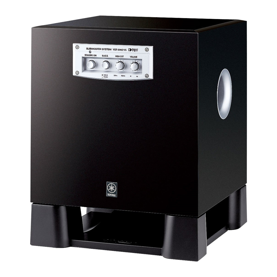
Yamaha YST-SW215 Service Manual
Subwoofer system
Hide thumbs
Also See for YST-SW215:
- Owner's manual (24 pages) ,
- Product catalog (44 pages) ,
- Owner's manual (142 pages)
Advertisement
Table of Contents
QQ
3 7 63 1515 0
TE
L 13942296513
CONTENTS
TO SERVICE PERSONNEL .......................................... 2
INTERNAL VIEW ........................................................... 2
REAR PANELS .......................................................... 3~4
www
.
1 0 0 8 5 4
http://www.xiaoyu163.com
YST-SW215
........................................ 3
............. 5~6
x
ao
y
i
http://www.xiaoyu163.com
8
SUBWOOFER SYSTEM
SERVICE MANUAL
This manual has been provided for the use of authorized YAMAHA
Retailers and their service personnel.
It has been assumed that basic service procedures inherent to the industry,
and more specifically YAMAHA Products, are already known and
understood by the users, and have therefore not been restated.
WARNING:
IMPORTANT:
Q Q
3
6 7
1 3
The data provided is believed to be accurate and applicable to the unit(s)
indicated on the cover. The research, engineering, and service departments
of YAMAHA are continually striving to improve YAMAHA products.
Modifications are, therefore, inevitable and specifications are subject to
change without notice or obligation to retrofit. Should any discrepancy
appear to exist, please contact the distributor's Service Division.
WARNING:
IMPORTANT:
BLOCK DIAGRAM ......................................................... 8
PRINTED CIRCUIT BOARD .................................... 9~10
SCHEMATIC DIAGRAM .............................................. 11
PARTS LIST ........................................................... 13~20
7
u163
.
2 9
9 4
2 8
IMPORTANT NOTICE
Failure to follow appropriate service and safety
procedures when servicing this product may result in
personal injury, destruction of expensive components,
and failure of the product to perform as specified. For
these reasons, we advise all YAMAHA product owners
that any service required should be performed by an
authorized YAMAHA Retailer or the appointed service
representative.
The presentation or sale of this manual to any individual
or firm does not constitute authorization, certification or
1 5
0 5
8
2 9
9 4
recognition of any applicable technical capabilities, or
establish a principle-agent relationship of any form.
Static discharges can destroy expensive components.
Discharge any static electricity your body may have
accumulated by grounding yourself to the ground buss in
the unit (heavy gauge black wires connect to this buss).
Turn the unit OFF during disassembly and part
replacement. Recheck all work before you apply power
to the unit.
m
co
P.O.Box 1, Hamamatsu, Japan
9 9
2 8
9 9
Advertisement
Table of Contents

Related Manuals for Yamaha YST-SW215


Summary of Contents for Yamaha YST-SW215
-
Page 1: Table Of Contents
YST-SW215 SERVICE MANUAL IMPORTANT NOTICE This manual has been provided for the use of authorized YAMAHA Retailers and their service personnel. It has been assumed that basic service procedures inherent to the industry, and more specifically YAMAHA Products, are already known and understood by the users, and have therefore not been restated. -
Page 2: To Service Personnel
YST-SW215 3 7 63 1515 0 AC LEAKAGE TO SERVICE PERSONNEL WALL EQUIPMENT TESTER OR OUTLET UNDER TEST EQUIVALENT 1. Critical Components Information Components having special characteristics are marked s and must be replaced with parts having specifications equal to those originally installed. -
Page 3: Specifications
YST-SW215 3 7 63 1515 0 SPECIFICATIONS / Type / Advanced Yamaha Active Servo Technology Weight / 11.5 kg (25 lbs. 6 oz.) 120 W (100 Hz, 5 Ω, 10% T.H.D.) Output Power / Finish Cherry Color ....... U, C, A, B, G, R, T, K, J models Input Sensitivity / Black Color ........ - Page 4 YST-SW215 3 7 63 1515 0 B, G models R model T model K model L 13942296513 J model u163 http://www.xiaoyu163.com...
-
Page 5: Disassembly Procedures
YST-SW215 3 7 63 1515 0 DISASSEMBLY PROCEDURES (Remove parts in the order as numbered.) Disconnect the power cable from the AC outlet. 1. Removal of Driver a. Remove 4 screws (1) and then remove the Base. (Fig. 1) b. - Page 6 YST-SW215 3 7 63 1515 0 3. Removal of Rear Panel Ass'y a. Remove 8 screws (4). (Fig. 3) * Screws (4) are identified with arrow marks ( b. Pull out the rear panel ass'y. (Fig. 3) a. Remove 2 screws (5). (Fig. 3) * Screws (5) are identified with arrow marks ( b.
-
Page 7: Confirmation Of Auto Standby Operation
YST-SW215 3 7 63 1515 0 CONFIRMATION OF AUTO STANDBY OPERATION / Setting 1) Turn off the power switch located on the rear panel. 2) In order to shorten the time required for operation check; connect a 10 kΩ resistor at both ends of R252 on the MAIN P.C.B. -
Page 8: Block Diagram
YST-SW215 3 7 63 1515 0 BLOCK DIAGRAM L 13942296513 u163 http://www.xiaoyu163.com... -
Page 9: Printed Circuit Board
YST-SW215 3 7 6 3 1 5 1 5 0 PRINTED CIRCUIT BOARD (Foil side) • Semiconductor Location DRIVER Ref. No. Location MAIN (6) P.C.B. MAIN ( 3 ) P.C.B. MAIN ( 1 ) P.C.B. – D202 IC10 IC11... - Page 10 YST-SW215 3 7 6 3 1 5 1 5 0 PRINTED CIRCUIT BOARD (Foil side) POWER MAIN (1) P.C.B. • Semiconductor Location Ref. No. Location D203 D204 D205 MAIN ( 5 ) P.C.B. IC202 Q207 Q208 Q209 MAIN ( 2 ) P.C.B.
-
Page 11: Schematic Diagram
YST-SW215 SCHEMATIC DIAGRAM IC1: STK404-120 Power Amp. 3 7 6 3 1 5 1 5 0 B.P.F L.P.F -14.6 10.7 10.7 10.0 14.8 14.0 10.7 L.P.F. POWER AMP PROTECTION 50.1 IC2, 4, 7, 10: µPC4570HA -14.6 50.0 Dual OP-Amp -0.1... - Page 12 YST-SW215 PARTS LIST 3 7 63 1515 0 ELECTRICAL PARTS WARNING Components having special characteristics are marked s and must be replaced with parts having specifications equal to those originally installed. Carbon resistors (1/6W or 1/4W) are not included in the ELECTRICAL PARTS List. For the parts No. of the carbon resistors, refer to last page.
-
Page 13: Parts List
YST-SW215 3 7 63 1515 0 P.C.B. MAIN L 13942296513 u163 New Parts http://www.xiaoyu163.com... - Page 14 YST-SW215 3 7 63 1515 0 P.C.B. MAIN L 13942296513 u163 New Parts http://www.xiaoyu163.com...
- Page 15 YST-SW215 3 7 63 1515 0 P.C.B. MAIN L 13942296513 u163 New Parts http://www.xiaoyu163.com...
- Page 16 YST-SW215 3 7 63 1515 0 P.C.B. MAIN L 13942296513 u163 New Parts http://www.xiaoyu163.com...
- Page 17 YST-SW215 3 7 63 1515 0 Parts List for Carbon Resistors Value 1/4W Type Part No. 1/6W Type Part No. Value 1/4W Type Part No. 1/6W Type Part No. 1.0 Ω 3100 3100 10 kΩ 7100 7100 HJ35 HF85...
- Page 18 YST-SW215 3 7 6 3 1 5 1 5 0 4-32 EXPLODED VIEW MECHANICAL PARTS 4-1 (3) 4-22 4-11 4-38 4-37 4-32 4-32 4-34 4-16 4-32 4-35 4-19 4-37 4-32 4-32 4-32 4-31 4-32 4-35 4-21 4-33 4-35 4-18...
- Page 19 YST-SW215 3 7 6 3 1 5 1 5 0 YST-SW215 1 3 9 4 2 2 9 6 5 1 3 w w w u 1 6 3 New Parts http://www.xiaoyu163.com...
Need help?
Do you have a question about the YST-SW215 and is the answer not in the manual?
Questions and answers