Table of Contents
Advertisement
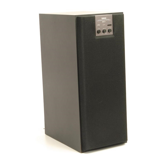
Thank you for selecting this YAMAHA Subwoofer System.
OWNER'S MANUAL
CONTENTS
Safety Instructions.................... 2
Supplied Accessories............... 3
Features ................................... 4
Placement ................................ 4
Connections ............................. 5
Adjusting Volume Balance...... 10
Control Transmitter ................. 12
Troubleshooting ...................... 12
Specifications ......................... 13
Active Servo Technology ........ 13
YST -SW200
Active Servo Processing Subwoofer System
High Frequency Cut-off Point (HIGH CUT) Control
IMPORTANT!
Please record the serial number of this
unit in the space below.
Model:
Serial No.:
The serial number is located on the rear
of the unit.
Retain this Owner's Manual in a safe
place for future reference.
WARNING
TO REDUCE THE RISK OF FIRE OR
ELECTRIC SHOCK, DO NOT EXPOSE
THIS UNIT TO RAIN OR MOISTURE.
Built-in 100W Power Amplifier
2 Way Selectability for Connections
Remote Control Capability
CAUTION: TO REDUCE THE RISK OF
ELECTRIC SHOCK, DO NOT REMOVE
COVER (OR BACK), NO USER-SERVICEABLE
PARTS INSIDE, REFER SERVICING TO
• Explanation of Graphical Symbols
PHASE Switch
Active Servo
Technology
CAUTION
RISK OF ELECTRIC SHOCK
DO NOT OPEN
QUALIFIED SERVICE PERSONNEL.
The lightning flash with arrowhead
symbol, within an equilateral triangle,
is intended to alert you to the
presence of uninsulated "dangerous
voltage" within the product's
enclosure that may be of sufficient
magnitude to constitute a risk of
electric shock to persons.
The exclamation point within an
equilateral triangle is intended to alert
you to the presence of important
operating and maintenance
(servicing) instructions in the
literature accompanying the
appliance.
Advertisement
Table of Contents

Related Manuals for Yamaha YST-SW200


Summary of Contents for Yamaha YST-SW200
-
Page 1: Table Of Contents
Thank you for selecting this YAMAHA Subwoofer System. OWNER’S MANUAL CONTENTS Safety Instructions... 2 Supplied Accessories... 3 Features ... 4 Placement ... 4 Connections ... 5 Controls and Their Functions ... 8 Adjusting Volume Balance... 10 Notes about the Remote Control Transmitter ... -
Page 2: Safety Instructions
SAFETY INSTRUCTIONS Read Instructions – All the safety and operating instructions should be read before the unit is operated. Retain Instructions – The safety and operating instructions should be retained for future reference. Heed Warnings – All warnings on the unit and in the operating instructions should be adhered to. -
Page 3: Supplied Accessories
This product, when installed as indicated in the instructions contained in this manual, meets FCC requirements. Modifications not expressly approved by Yamaha may void your authority, granted by the FCC, to use the product. 2. IMPORTANT : When connecting this product to accessories and/or another product use only high quality shielded cables. -
Page 4: Features
FEATURES • This subwoofer system employs YAMAHA Active Servo Technology which YAMAHA developed for reproducing higher quality super-bass sound. (Refer to page 13 for details on Active Servo Technology.) This unit does not only enhance bass frequency response of sound output in your audio system, but, by reproducing... -
Page 5: Connecting To Speaker Terminals
CONNECTING TO SPEAKER TERMINALS OF THE AMPLIFIER • Disconnect your main speakers from the amplifier and connect them to this unit. • To connect this unit to the amplifier, use the provided speaker cords. If using one YST-SW200 Right speaker This unit... -
Page 6: Connecting To Unit’s Output/Input Terminals
If your amplifier has two sets of speaker terminals Right speaker Connecting to this unit’s OUTPUT/INPUT terminals For connections, use speaker wires of the proper gauge, cut as short as possible. If the connections are faulty, no sound will be heard from the speakers. Make sure that the polarity of the speaker wires is correct, that is, + and –... -
Page 7: Connecting To Line Output Terminals
• Leave the main speakers connected to the amplifier. • Line output terminals may be labeled PRE OUT, REC OUT or SUBWOOFER OUT. * For PRE OUT terminal connection, the amplifier must possess at least two sets of PRE OUT terminals. With some amplifiers with only one set of PRE OUT terminals, connection can result in no sound from the main left and right speakers. -
Page 8: Controls And Their Functions
CONTROLS AND THEIR FUNCTIONS Front panel OUTPUT POWER HIGH CUT VOLUME 40 Hz 140 Hz Rear panel OUTPUT INPUT2 PHASE TO SPEAKERS NOM REV FROM AMPLIFIER INPUT1 Remote control transmitter OUTPUT POWER HIGH CUT VOLUME 40 Hz 140 Hz OUTPUT INPUT2 TO SPEAKERS FROM AMPLIFIER... - Page 9 POWER indicator Illuminates when the POWER switch is turned ON, and goes off when turned OFF. * STANDBY mode (Australia, U.K. and Europe models) While the power is on, pressing the POWER key on the remote control transmitter switches the unit to the STANDBY mode.
-
Page 10: Adjusting Volume Balance
VOLUME 40 Hz 140 Hz Rear Panel OUTPUT INPUT2 TO SPEAKERS FROM AMPLIFIER INPUT1 (except PRE OUT or SUBWOOFER OUT terminals) of the amplifier, you must adjust the volume controls of this unit and the amplifier individually. PHASE NOM REV... -
Page 11: Frequency Characteristics
FREQUENCY CHARACTERISTICS Adjustment of the VOLUME control, the HIGH CUT control and the PHASE switch should be changed according to the main speakers, listening condition, the source, etc. The following figures show the optimum adjusting level of each control and the frequency characteristics on the condition that this unit is combined with a typical speaker system. -
Page 12: Notes About The Remote Control Transmitter
If the unit fails to operate normally, check the following points to determine whether the fault can be corrected by the simple measures suggested. If it cannot be corrected, or if the fault is not listed in the SYMPTOM column, disconnect the power cord and contact your authorized YAMAHA dealer or service center for help. SYMPTOM Power is not supplied even though the POWER switch is ON. -
Page 13: Specifications
SPECIFICATIONS Speaker Unit ...18 cm (7-1/16”) cone woofer (JA1815) Amplifier Output ...100W/5 ohms (THD 0.1%, 100 Hz) High-Cut Filter...40 Hz–140 Hz (–24 dB/oct.) Frequency Response ...20 Hz–160 Hz (–10 dB) Power Supply U.S.A. and Canada models...AC 120V, 60 Hz Australia and U.K. models...AC 240V, 50 Hz Europe model ...AC 230V, 50 Hz General model ...AC 110/120/220/240V, 50/60 Hz ACTIVE SERVO TECHNOLOGY... - Page 14 YAMAHA ELECTRONICS (UK) LTD. YAMAHA HOUSE, 200 RICKMANSWORTH ROAD WATFORD, HERTS WD1 7JS, ENGLAND YAMAHA SCANDINAVIA A.B. J A WETTERGRENS GATA 1, BOX 30053, 400 43 VÄSTRA FRÖLUNDA, SWEDEN YAMAHA MUSIC AUSTRALIA PTY, LTD. 17-33 MARKET ST., SOUTH MELBOURNE, 3205 VIC., AUSTRALIA...
Need help?
Do you have a question about the YST-SW200 and is the answer not in the manual?
Questions and answers