Table of Contents
Advertisement
Service Literature
WARNING
Improper installation, adjustment, alteration, service or
maintenance can cause personal injury, loss of life, or
damage to property.
Installation and service must be performed by a licensed
professional installer (or equivalent) or a service agency.
IMPORTANT
The Clean Air Act of 1990 bans the intentional venting of
refrigerant (CFCs, HCFCs AND HFCs) as of July 1,
1992. Approved methods of recovery, recycling or
reclaiming must be followed. Fines and/or incarceration
may be levied for noncompliance.
WARNING
Electric Shock Hazard. Can cause injury
or death. Unit must be grounded in
accordance with national and local
codes.
Line voltage is present at all components
when unit is not in operation on units with
single-pole contactors. Disconnect all
remote electric power supplies before
opening access panel. Unit may have
multiple power supplies.
Corp. 0923−L10
01−2010
T−CLASSt
TPA*S4
M and T Voltage Units
Page 1
TABLE OF CONTENTS
Specifications and Electrical Data
Unit Dimensions
. . . . . . . . . . . . . . . . . . . . . . . . . . . . . . . . .
Typical Control Panel Parts Arrangement
Typical Unit Parts Arrangement
Model Number Identification
Unit Components
. . . . . . . . . . . . . . . . . . . . . . . . . . . . . . . .
General Information
. . . . . . . . . . . . . . . . . . . . . . . . . . . . .
Operating Gauge Set and Service Valves
Recovering Refrigerant from Existing System
Unit Placement
. . . . . . . . . . . . . . . . . . . . . . . . . . . . . . . . .
New or Replacement Line Set
Metering Devices and Flushing the System
Testing for Leaks
. . . . . . . . . . . . . . . . . . . . . . . . . . . . . . .
Evacuating the System
Electrical Connections
Servicing Unit Void of Charge
Unit Start−Up
. . . . . . . . . . . . . . . . . . . . . . . . . . . . . . . . . . .
System Refrigerant
. . . . . . . . . . . . . . . . . . . . . . . . . . . . .
System Operation
. . . . . . . . . . . . . . . . . . . . . . . . . . . . . .
Defrost System
. . . . . . . . . . . . . . . . . . . . . . . . . . . . . . . .
Maintenance
. . . . . . . . . . . . . . . . . . . . . . . . . . . . . . . . . . .
Start−Up and Performance Checklist
Wiring Diagrams and Sequence of Operations
The TPA*S4 is a commercial split-system heat pump. All
major components (indoor blower and coil) must be
matched according to Lennox recommendations for the
compressor to be covered under warranty. Refer to the
Engineering Handbook for approved system matchups.
IMPORTANT
This model is designed for use in expansion valve
systems only. An indoor check expansion valve
approved for use with
ordered separately, and installed prior to operating the
system.
This instruction is specifically for the following model
voltage configurations:
S
M Voltage
380/420VAC, 3−Phase, 50 Hertz
S
T Voltage
220/240VAC, 1−Phase, 50 Hertz
TPA*S4
M and T Voltages
. . . . . . . . . . . . . . . . . .
. . . . . . . . . . .
. . . . . . . . . . . . . . . . . . .
. . . . . . . . . . . . . . . . . . . . . .
. . . . . . . . . . .
. . . . . .
. . . . . . . . . . . . . . . . . . . .
. . . . . . . .
. . . . . . . . . . . . . . . . . . . . . . . . . .
. . . . . . . . . . . . . . . . . . . . . . . . . .
. . . . . . . . . . . . . . . . . . . .
. . . . . . . . . . . . . .
HFC−410A
refrigerant must be
2
2
4
5
5
6
8
8
10
11
12
15
16
17
18
20
20
20
24
24
24
28
. . . . .
29
Advertisement
Table of Contents

Subscribe to Our Youtube Channel
Related Manuals for Lennox T?CLASS TPA024S4


Summary of Contents for Lennox T?CLASS TPA024S4
- Page 1 (CFCs, HCFCs AND HFCs) as of July 1, major components (indoor blower and coil) must be 1992. Approved methods of recovery, recycling or matched according to Lennox recommendations for the reclaiming must be followed. Fines and/or incarceration compressor to be covered under warranty. Refer to the may be levied for noncompliance.
-
Page 2: Specifications And Electrical Data
Specifications and Electrical Data1 SPECIFICATIONS − SINGLE PHASE General Model No. TPA024S4 TPA036S4 TPA048S4 Data Nominal kW 10.5 14.0 Connections Liquid line o.d. − in. (sweat) Vapor line o.d. − in. Refrigerant (R−410A) furnished 2.95 kg (6 lbs. 8 oz.) 2.86 kg (6 lbs. - Page 3 Heating Air Conditioning and Refrigeration type circuit breaker or fuse. Refer to local codes to determine wire, fuse and disconnect size requirements. OPTIONAL ACCESSORIES For update−to−date information, see any of the following publications: Lennox TPA*S4 Engineering Handbook Lennox Commercial Price Book Page 3...
-
Page 4: Unit Dimensions
Unit Dimensions − inches (mm)2 Outdoor Coil Fan Discharge Air Compressor Electrical Vapor and Liquid Inlets Line Connections Optional Unit Stand-off Kit (4) (Field−installed) 2-3/4 (70) 2 (51) SIDE VIEW SIDE VIEW 3/4 (19) Model No. TPA024S4N41T 24−1/4 (616) 33−1/4 (845) 32−1/2 (826) TPA036S4N41M 24−1/4 (616) -
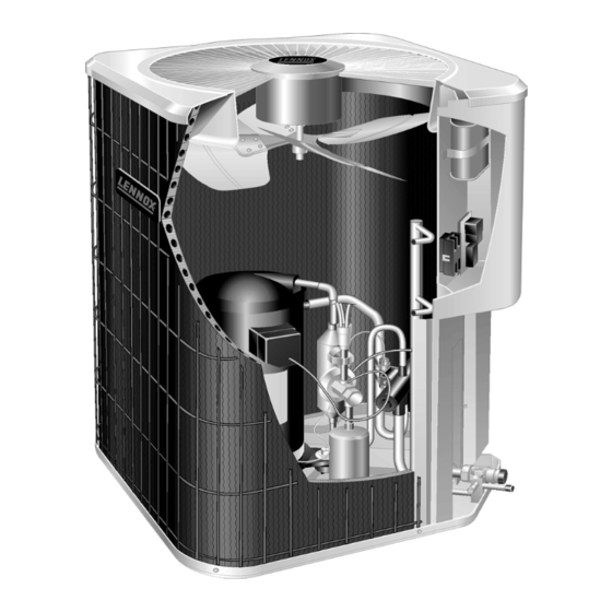
Page 5: Typical Unit Parts Arrangement
Typical Unit Parts Arrangement4 NOTE: PLUMBING LAYOUT MAY VARY SLIGHTLY BETWEEN MODEL SIZES. COMPRESS0R COMPRESSOR HARNESS DISCHARGE LINE DEFROST THERMOSTAT MUFFLER LOW PRESSURE SWITCH CHECK EXPANSION VALVE REVERSING VALVE EQUALIZER LINE REVERSING VALVE SOLENOID BI−FLOW FILTER DRIER TRUE SUCTION PORT HIGH PRESSURE SWITCH (S4) VAPOR LINE SERVICE VALVE LIQUID LINE SERVICE VALVE... -
Page 6: Unit Components
IMPORTANT RACEWAY This unit must be matched with an indoor coil as speci- REMOVE (7) SCREWS fied in Lennox Engineering Handbook. Coils previous- SECURING FAN GUARD. REMOVE FAN GUARD/FAN AS- Remove (4) nuts ly charged with HCFC−22 must be flushed. - Page 7 DETAIL A SUCTION SUCTION INTERMEDIATE PRESSURE ORBITING SCROLL CRESCENT SHAPED GAS POCKET STATIONARY SCROLL DETAIL B SUCTION POCKET FLANKS SEALED BY CENTRIFUGAL SUCTION SUCTION FORCE MOVEMENT OF ORBIT DISCHARGE DETAIL C DETAIL D HIGH PRESSURE GAS POCKET Figure 3. Scroll Compressors REVERSING VALVE L1 AND SOLENOID A refrigerant reversing valve with electromechanical DISCHARGE...
-
Page 8: General Information
(tips) of the scrolls as illustrated in recess. Figure 5. During a single orbit, several pockets of gas are See the Lennox Service and Application Notes #C−08−1 compressed simultaneously providing smooth continuous for further details and information. -
Page 9: Service Valves
SERVICE VALVES SERVICE PORT CAP SERVICE PORT VARIOUS TYPES SERVICE PORT CORE (VALVE STEM SHOWN OPEN TO BOTH INDOOR AND CLOSED) INSERT HEX OUTDOOR UNITS WRENCH HERE SERVICE PORT CAP VALVE STEM FRONT-SEATED SERVICE PORT SERVICE PORT CORE TO INDOOR (VALVE STEM UNIT SHOWN OPEN) -
Page 10: Recovering Refrigerant From Existing System
Recovering Refrigerant from Existing System9 RECOVERING REFRIGERANT FROM SYSTEM DISCONNECT POWER CONNECT MANIFOLD GAUGE SET Disconnect all power to the existing outdoor unit at the disconnect Connect a gauge set, clean recovery cylinder and a recovery switch or main fuse box/breaker panel. machine to the service ports of the existing unit. -
Page 11: Unit Placement
Unit Placement10 See Unit Dimensions on Page3 for sizing mounting slab, INSTALL UNIT AWAY FROM WINDOWS platforms or supports. Refer to Figure 7 for mandatory installation clearance requirements. TWO 90° ELBOWS INSTALLED IN LINE SET WILL REDUCE LINE SET VIBRATION. Figure 8. -
Page 12: New Or Replacement Line Set
LINE SET ISOLATION from the outdoor unit (braze connections) to the indoor unit CAUTION coil (flare or braze connections). Use Lennox L15 (braze, non−flare) series line set, or use field−fabricated refrigerant Brazing alloys and flux contain materials which are lines as listed in Table 2. - Page 13 LINE SET IMPORTANT Refrigerant lines must not contact structure. INSTALLATION REFRIGERANT LINE SET INSTALLING Line Set Isolation The following illustrations are VERTICAL RUNS (NEW CONSTRUCTION SHOWN) examples of proper refrigerant line set isolation: NOTE Insulate liquid line when it is routed through areas where the surrounding ambient temperature could become higher than the REFRIGERANT LINE SET TRANSITION...
- Page 14 BRAZING NOTE − Use silver alloy brazing rods with five or six percent minimum silver alloy for copper−to−copper brazing, 45 percent alloy for copper−to−brass and copper−to−steel brazing. CONNECTIONS13 CAP AND CORE REMOVAL Remove service cap and core CUT AND DEBUR from both the vapor and liquid line service ports.
-
Page 15: Metering Devices And Flushing The System
Metering Devices and Flushing the System14 TYPICAL EXPANSION VALVE REMOVAL AND FLUSHING REPLACEMENT PROCEDURE (Uncased Coil Shown) LINE SET AND INDOOR COIL STUB END TWO PIECE PATCH PLATE LIQUID LINE EXPANSION (UNCASED COIL ONLY) ORIFICE VALVE TYPICAL FIXED ORIFICE REMOVAL HOUSING DISTRIBUTOR TUBES... -
Page 16: Leak Testing The System
Leak Testing the System15 LEAK TEST LINE SET AND INDOOR COIL NOTE Normally, the high pressure hose is connected to the liquid line port. How- ever, connecting it to the vapor port better protects the manifold gauge set from high pressure damage. -
Page 17: Evacuating The System
Evacuating the System16 EVACUATING MANIFOLD GAUGE SET LINE SET AND INDOOR COIL CONNECT GAUGE SET HIGH NOTE Remove cores from service valves (if not al- ready done). Connect low side of manifold gauge set with 1/4 SAE in−line tee to vapor line service valve A34000 1/4 SAE TEE WITH Connect high side of manifold gauge... - Page 18 temperatures and pressures present during operation of IMPORTANT an air conditioning system. Non−condensables and water suction combine with refrigerant to produce substances Use a thermocouple or thermistor electronic vacuum that corrode copper piping and compressor parts. gauge that is calibrated in microns. Use an instrument capable of accurately measuring down to 50 microns.
-
Page 19: Control Wiring
ROUTING HIGH VOLTAGE/ GROUND AND CONTROL WIRING HIGH VOLTAGE / GROUND WIRES Any excess high voltage field wiring should be trimmed and secured away from any low voltage field wiring. To facilitate a conduit, a cutout is located in the bottom of the control panel. Connect conduit to the control panel using a proper conduit fitting. CONTROL WIRING DEFROST CONTROL THREE PHASE... -
Page 20: System Refrigerant
GAUGE SET MANIFOLD GAUGE SET CONNECTIONS FOR TESTING AND CHARGING HIGH TRUE SUCTION PORT CONNECTION OUTDOOR UNIT REFRIGERANT TANK CHARGE IN LIQUID PHASE DIGITAL SCALE TEMPERATURE SENSOR (LIQUID LINE) LIQUID LINE TO LIQUID SERVICE LINE SERVICE PORT VALVE TEMPERATURE SENSOR Close manifold gauge set valves and connect the center hose to a cylinder of HFC−410A. - Page 21 ADDING OR REMOVING REFRIGERANT This system uses HFC−410A refrigerant which operates at much higher pressures than HCFC−22. The pre−installed liquid line filter drier is approved for use with HFC−410A only. Do not replace it with components designed for use with HCFC−22. This unit is NOT approved for use with coils which use capillary tubes or fixed orifices as a refrigerant metering device.
- Page 22 WEIGH IN SUBCOOLING method for adding initial refrigerant charge, and then use method for verifying refrigerant charge. WEIGH IN CALCULATING SYSTEM CHARGE FOR OUTDOOR UNIT VOID OF CHARGE CHARGING METHOD If the system is void of refrigerant, first, locate and repair any leaks and then weigh in the refrigerant charge into the unit.
- Page 23 Table 3. Subcooling (SC) Values TXV System − ºF Table 4. Subcooling (SC) Values TXV System − ºF (ºC) +1ºF (0.5ºC) (ºC) +1ºF (0.5ºC) T Voltage 220/240VAC, 1−Phase, 50 Hertz M Voltage 380/420VAC, 3−Phase, 50 Hertz 5F(5C)* 5F(5C)* −024 −036 −048 −036 −048...
-
Page 24: System Operation
Table 7. HFC−410A Temp. (°F) − Pressure (Psig) °F °C Psig °F °C Psig −40 −40.0 11.6 15.6 −35 −37.2 14.9 18.3 −30 −34.4 18.5 21.1 −25 −31.7 22.5 23.9 −20 −28.9 26.9 26.7 −15 −26.1 31.7 29.4 −10 −23.3 36.8 32.2 −5... - Page 25 Defrost Control Timing Pins Table 8. Defrost Control Board Diagnostic LEDs Each timing pin selection provides a different DS2 Green DS1 Red Condition accumulated compressor run time period during one thermostat run cycle. This time period must occur before Power problem a defrost cycle is initiated.
- Page 26 TEST Placing the jumper on the field test pins allows the technician to: Clear short cycle lockout Clear five−strike fault lockout Cycle the unit in and out of defrost mode Place the unit in defrost mode to clear the coil When Y1 is energized and 24V power is being applied to the Control, a test cycle can be initiated by placing a jumper on the Control’s TEST pins for 2 to 5 seconds.
-
Page 27: Maintenance
Indoor Unit Installation and service must be performed by a licensed 1. Clean or change filters. professional installer (or equivalent) or a service agency. 2. Lennox blower motors prelubricated permanently sealed. No more lubrication is needed. Maintenance and service must be performed by a qualified 3. -
Page 28: Start−Up And Performance Checklist
Checklists24 Field Operational Checklist Cooling*** Heating*** Expected results Expected results Unit Readings Y2 Second First during Y2 demand Second during Y2 demand First Stage Stage Stage (Toggle switch On) Stage (Toggle switch On) Compressor Voltage Same Same Amperage Higher Higher Condenser Fan motor Amperage Same or Higher... -
Page 29: Wiring Diagrams And Sequence Of Operations
Wiring Diagrams and Sequence of Operations27 M Voltage 380/420v (3PH) 50Hz COOLING: Internal thermostat wiring energizes terminal O by cooling mode selection, energizing the reversing valve L1. 1. Demand initiates at Y1 in the thermostat. 2. Assuming high pressure switch S4 and low pressure switch S87 are closed, 24VAC energizes compressor contactor 3. - Page 30 Figure 19. Typical Field Wiring Diagram M Voltage 380/420v (3PH) 50Hz Page 30...
- Page 31 T VOLTAGE 220/240V (1PH) 50HZ COOLING: Internal thermostat wiring energizes terminal O by cooling mode selection, energizing the reversing valve L1. 1. Demand initiates at Y1 in the thermostat. 2. Assuming high pressure switch S4 and low pressure switch S87 are closed, 24VAC energizes compressor contactor 3.
- Page 32 Figure 20. Typical Field Wiring Diagram T Voltage 220/240v (1PH) 50Hz Page 32...
Need help?
Do you have a question about the T?CLASS TPA024S4 and is the answer not in the manual?
Questions and answers