Harman Kardon CDR20 Service Manual
Harman kardon cdr20 dual tray cd/cd-r/cd-rw recorder/player
Hide thumbs
Also See for CDR20:
- Owner's manual (24 pages) ,
- Quick start manual (4 pages) ,
- Specifications (2 pages)
Table of Contents
Advertisement
harman/kardon
Dual Tray CD/CD-R/CD-RW Recorder/Player
SERVICING PRECAUTIONS . . . . . . . . ... . . .. .2
ESD PRECAUTIONS................................... 4
SPECIFICATIONS . . . . . . . . . . . . . . . . . . . .. . . .5
FRONT PANEL CONTROLS ........... . . .. . . .. . 6
FRONT PANEL DISPLAY ........... . . .. . . . . . . 8
REAR PANEL CONNECTIONS. . . . . . ......... 10
REMOTE CONTROL FUNCTIONS. . . . . .. .. ...11
INSTALLATION/CONNECTIONS. .................13
BASIC TROUBLESHOOTING GUIDE............ 14
Model
SERVICE MANUAL
harman/kardon, Inc.
250 Crossways Park Dr.
Woodbury, New York 11797
CDR20
CONTENTS
BULLETIN HK2001-04..................................16
BULLETIN HK2001-06........... .. . . . . ........ .. . 17
DETAILED TROUBLESHOOTING GUIDE .......19
BLOCK DIAGRAMS . . . . . . . . .. . . .. . .. .. . . . .36
EXPLODED VIEWS . . . . . . . . . . . .. . .. . .. . . . . 39
MECHANICAL PARTS LIST........... .. . . . . . .. . 42
ELECTRICAL PARTS LIST . . . . . .. . . ..... .......44
PCB DRAWINGS. . . . . . . . . . . . ..... . .. . . . .. . . 65
SCHEMATIC DIAGRAMS . . . . . .................... 71
WIRING DIAGRAM......................................85
Advertisement
Table of Contents
Troubleshooting

Related Manuals for Harman Kardon CDR20


Summary of Contents for Harman Kardon CDR20
-
Page 1: Table Of Contents
PCB DRAWINGS... . …... . 65 BASIC TROUBLESHOOTING GUIDE………... 14 SCHEMATIC DIAGRAMS ..……………….. 71 SPECIAL NOTES ON CDR20 RECORDING… 15 WIRING DIAGRAM………………………………..85 harman/kardon, Inc. -
Page 2: Servicing Precautions
CDR20 SERVICING PRECAUTIONS NOTES REGARDING HANDLING OF THE PICK-UP 1. Notes for transport and storage 1) The pick-up should always be left in its conductive bag until immediately prior to use. 2) The pick-up should never be subjected to external pressure or impact. - Page 3 CDR20 NOTES REGARDING COMPACT DISC PLAYER REPAIRS 1. Preparations 1) Compact disc players incorporate a great many ICs as well as the pick-up (laser diode). These compo- nents are sensitive to, and easily affected by, static electricity. If such static electricity is high voltage, components can be damaged, and for that reason components should be handled with care.
-
Page 4: Esd Precautions
CDR20 ESD PRECAUTIONS Electrostatically Sensitive Devices (ESD) Some semiconductor (solid state) devices can be damaged easily by static electricity. Such components com- monly are called Electrostatically Sensitive Devices (ESD). Examples of typical ESD devices are integrated cir- cuits and some field-effect transistors and semiconductor chip components. The following techniques should be used to help reduce the incidence of component damage caused by static electricity. -
Page 5: Specifications
CDR20 CDR20 SPECIFICATIONS Playback Sampling Frequency 44.1 kHz D/A Conversion 96kHz, Multi-Bit Delta-Sigma Conversion Oversampling 128 Times Playback Specifications Frequency Response 2Hz – 20,050Hz Playback S/N 105dB Playback Dynamic Range 105dB Playback THD 0.005% / –88dB Analog Audio Output 2V RMS, ±... -
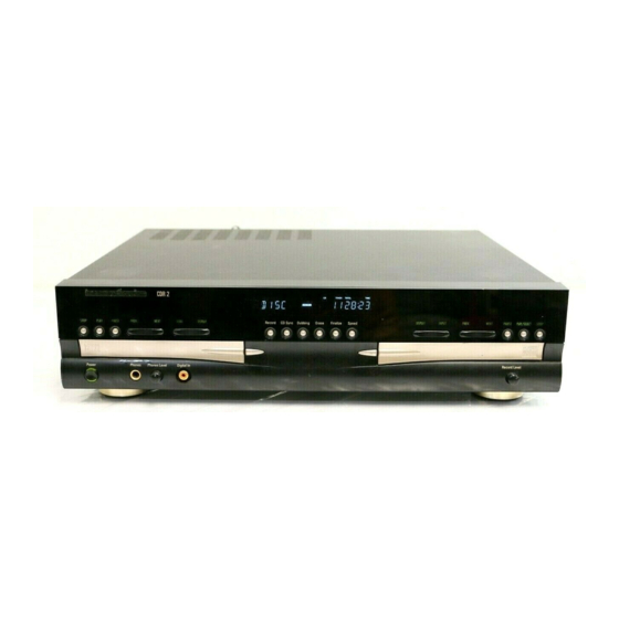
Page 6: Front Panel Controls
CDR20 Front-Panel Controls ¯ ¸ ˆ Ù Ú Ó ˘ ˜ Û Ò & ı Ô 1 Power Switch @ Finalize Ò Record-Deck Display Select 2 Status-Mode Indicator # Speed Ú Information Display 3 Play Deck $ Record-Deck Open Û... - Page 7 CDR20 Front-Panel Controls @ Finalize: Press this button when a record- Ô Record Deck Previous: This button has ˆ Play-Deck Next: When a disc is playing in the Play Deck 3, press and hold this button to ing is complete to initiate the finalization two functions.
-
Page 8: Front Panel Display
CDR20 Front-Panel Information Display A Random Indicators J Dual-Play Indicator S CD Indicators B Program Indicators K Information Displays T Record Indicator C Level Indicators L Time Indicators U Finalize Indicator D Repeat Indicators M Remaining-Time Indicators V Erase Indicator... - Page 9 CDR20 Front-Panel Information Display L Time Indicators: These indicators light in R Sample-Rate Converter: This indicator X Analog Indicator: This indicator lights conjunction with one of the time indicators lights when the Sample-Rate Converter is in use when an analog source is being recorded.
-
Page 10: Rear Panel Connections
ª Remote IR Input: Connect the output of a remote infrared sensor or the remote control ∞ Record Deck (CDR) Coaxial-Digital output of another compatible Harman Kardon Output: This jack carries the digital audio out- product to this jack. This will enable the remote put signal from the Record Deck %. -
Page 11: Remote Control Functions
CDR20 Remote Control Functions a Power-On Button b Play Deck (CDP) Display Control c Play Deck (CDP) Open d Play Deck (CDP) Select e Program f Reverse Search g Single h Program Check i Previous-Track Skip j Play/Select k Random Play... - Page 12 CDR20 Remote Control Functions a Power-On Button: Press this button to l Dub: Press this button to begin a dub. See w CD Sync: Press this button once to begin turn the CDR 20 on. Note that in order for this page 20 for more information on dubbing.
-
Page 13: Installation/Connections
CDR20 Installation and Connections Important Note: To prevent possible damage Play-Deck Connections To make recordings from external digital to your speakers or other components in your The rear-panel connections labeled “CDP” refer sources, such as a CD, DVD or MD player, con- to the outputs of the Play Deck 3, which nect the CDR Coax-In jacks §6 or CDR... -
Page 14: Basic Troubleshooting Guide
• Replace the disc with a blank CD-R or CD-RW Audio disc NO AUDIO a non-audio disc is in the Record Drawer % • There is an internal problem with the CDR 20 • Contact an authorized Harman Kardon service depot SVC-1... -
Page 15: Special Notes On Cdr20 Recording
CDR20 Notice - Important information regarding the use of the harman/kardon CDR 20. 1) Complaint: “I cannot record at x2 or x4 speed. Unit switched back to 1x speed” Possible explanations: a) Programmed play only records at x1 speed. You cannot record at x2 or x4 speeds when programmed dub is attempted (to record only certain tracks on a CD) b) Some brands of CDR do not allow recording at x2 or x4 speed. -
Page 16: Bulletin Hk2001-04
Subject: Delay in Reading Blank Disc In the event you receive a CDR20 CD Player/Recorder with the complaint: “The unit has an excessive delay (over 45 seconds) when initially reading a blank CDR disc in the Record drawer, after it’s inserted”, perform the modification below:... -
Page 17: Bulletin Hk2001-06
Model: CDR20 Subject: Noise when dubbing at x4 speed In the event you receive a CDR20 CD Player/Recorder with the complaint: “There is noise being generated on a recorded CDR at x4 speed”, perform the modification below: Synopsis: Change resistor R230 from 100 ohms to 22 ohms. - Page 18 CDR20 Service bulletin # H/K2001-06 November 2001 FACTORY MODIFIED UNITS (120v) All Serial Numbers begin with prefix LG0003- 28111 28335 28415 28910 29164 29655 28230 28336 28417 28914 29172 29659 28234 28337 28418 28918 29181 29666 28241 28338 28431...
-
Page 19: Detailed Troubleshooting Guide
CDR20 TROUBLESHOOTING GUIDE 1. Initial Lead-in Operation 2. Trouble List(Circuit) (In the Initial Lead-in Operation Mode) A. Pick-Up doesn’t move to the inner-track. B. Pick-Up lens doesn’t move up and down. C. Disc doesn’t rotate. D. The Laser(RED) of Pick-Up doesn’t light. - Page 20 CDR20 3. Troubleshooting Guide(In the Initial Lead-in Operation Mode)
- Page 21 CDR20...
- Page 22 CDR20...
- Page 23 CDR20...
- Page 24 CDR20 TROUBLESHOOTING GUIDE FOR CD-RW BOARD Reset or Power Check. •Is the Pin 1, 3 of PN105 5V? • Check the PN105. •Is the Pin 5 of PN105 12V? • Check the SMPS board. Does the pin1 • Check the IC101(RESET IC).
- Page 25 CDR20 System Check. Load tray without inserting disc. Does Tray operate normally? Go to "Tray operating is abnormal" Does Pick-up move to inside? Go to "Sled operating is abnormal" Go to "Spindle opreating is Does Spindle Motor rotate in a moment? abnormal"...
- Page 26 CDR20 Tray operating is abnormal. (Tray open/close doesn't work) •Check the connection of IC409 pin 12. •Replace the IC409(M62352). Is threre Tray control signal intput? •Check the communication line between (IC501 pin26) IC409 and IC701(MICOM). •Check the connection of IC701...
- Page 27 CDR20 Sled operating is abnormal. Is there Check the connection of IC701 Sled control signal output? Replace the IC701(MICOM) pin 85 (IC701 pin 85) Is there Check the connection of IC502 Sled drive voltage input? pin 17. (IC501 pin 23)
- Page 28 CDR20 Spindle operating is abnormal. Is there Spindle •Check the connection of IC201 pin2. Is there DMO signal input? control signal input? (IC509 pin5) •Replace the IC201(OTI-9790) (IC510 pin 22) Is there Spindle •Replace the IC509(NJM3404). control signal output? (IC509 pin 7) Replace the IC508(BU4053).
- Page 29 CDR20 Focus Actuator operating is abnormal •Check the connection of IC201 pin207. Is there •Check the communication line between Focus Search control signal IC201 and IC701 input? (IC510 pin 3) •Replace the IC201(OTI-9790) •Check the connection of IC701 Is there Focus Search Is Act_Mute signal “L”?
- Page 30 CDR20 Spindle control is abnormal 2 (CD-ROM Disc) Is there RRF signal input? Go to “RF output is abnormal” (IC413 pin 3) Is there RFDC signal input? Replace the IC413(EL2245). (IC401 pin 85) Does Tracking Go to “Track servo is unstable”...
- Page 31 CDR20 Disc recognition is abnormal Is there Is there CDR/RW signal input RECD1, RECD2 signal Go to “RF output is abnormal” normally?(IC601 pin 33) output normally? (IC401 pin 48,49) Go to “Track Servo is unstable” Replace IC701 (MICOM) RF output is abnormal Is there •Check the PICK UP FFC.
- Page 32 CDR20 Focus Servo is unstable Is FE signal output normal in Focusing Check the IC401(CXA2551R). Up/Down? (IC401 pin 56) Go to “RF output is abnormal” Is FAQ signal output normal in Focusing Replace the IC201(OTI-9790). Up/Down? (IC201 pin 207) Go to “Focus Actuator operating...
- Page 33 CDR20 In case of writing fail. Nomal Case Cheak the Media CD-R Check disc Label. or CD-RW? Romove the Dust, Fingerprint Dose the disc have and if the disc has long width any Dust, Scratch, Scratch, change it. Fingerprint...? Finalized Disc? Eject Disc.
- Page 34 CDR20 Writing Part Check. Refer “Laser is abnormal”. Load tray with CD-R/RW Disc. Start Recording or dubbing. Does the unit becomes stand-by mode to record/dubbing? •Check the communication Iines between IC701 and IC201. •Check and replace the 701. Dose Writing finish...
- Page 35 CDR20 BETA Measurement circuit ceck After inserting Test Dise(TCD-784), start playing. •Check the connection of IC401 pin 86. IC401 Pin 86(RRF):3+/-1.0V? •Check and replace the IC401 (CXA2551R). •Check the connection of IC407. RRFIN:2+/0.7V? •Check and replace the IC407. (IC401 PIN85) •Check the connection of IC701 pin 20.
-
Page 36: Block Diagram
BLOCK DIAGRAM harman/kardon CDR20 • CD RECORD SECTION disc CXA2551R OTI9790 RF AMP Spindle RF/Servo Signal Wobble DRAM motor Driver DSP + SERVO ALPC Decoder I / V AMP Encoder Pick -up 17.43 MHz (KRS-220c ATIP Demod. :Sony) CPLD Write Strategy... - Page 37 • CD PLAY SECTION harman/kardon CDR20...
- Page 38 • IO SECTION harman/kardon CDR20 COAXIAL IN (1) 74HC04 74HC04 BUFFER BUFFER H/P OUT LRCK DATA BCLK BU4053 BU4053 AK4394 AK4394 ANALOG P OUTPUT (DAC) (DAC) POWER ANALOG R OUTPUT DOWN MUTE DEMPH 74HC04 RELAY ANALOG INPUT 74HC04 BU4053 BU4053...
-
Page 39: Exploded Views
REC 8K(ADR-600 KTH1) 4940S-6941A KNOB VOLUME(ADR-600 KTH1) 3720S-P014K PANEL BACK(ADR601. KTH1) 3140S-P911C CHASSIS TOP(ADR-600KTH1 HARMAN) 3846S-0208A MARK HARMAN KARDON BADGE 4766R-0003A FELT FOOT(19.7*19.7) 3550S-1027B COVER RW DECK(AIR VENT ADR-600 KTH1) 6410RAHS02A POWER CORD AP-10W NI SP2 CORE 80 STP SANG... - Page 40 CDR20 • CD PLAY SECTION...
- Page 41 CDR20 • CD RECORD SECTION...
-
Page 42: Mechanical Parts List
CDR20 SECTION 5 REPLACEMENT PARTS LIST A : CDR 20 KTH1K RUN : 2000.10.28 . Mechanical Section NSP : Not Service Parts LOCA. NPART NO.(LG) DESCRIPTION SPECIFICATION REMARKS ASSEMBLY SECTION 6721R-0301A DECK ASSY,VIDEO ACDR(Q1,PLYER) 4405H-1064A MECHANISM ASSY MAIN LOADING(GM-RT1332A) - Page 43 KNOB VOLUME(ADR-600 KTH1) 3720S-P014K PANEL BACK(ADR601. KTH1) 3140S-P911C CHASSIS TOP(ADR-600KTH1 HARMAN) 3846S-0208A MARK HARMAN KARDON BADGE 4766R-0003A FELT FOOT(19.7*19.7) 3550S-1027B COVER RW DECK(AIR VENT ADR-600 KTH1) 6410RAHS02A POWER CORD AP-10W NI SP2 CORE 80 STP SANG . Packing Accessory Section...
-
Page 44: Electrical Parts List
CDR20 A : CDR 20 KTH1K . Electrical Section RUN : 2000.10.28 AL LOCA. NO. PART NO.(LG) A DESCRIPTION SPECIFICATION CAPACITOR C249 0CH1104K946 O CAPA,CHIP CERAMIC M/L H.D F/S 0.1UF 50V Z Y5V(F) 2012 R/TP C101 0CE4766J618 O CAPACITOR,ELECTROLYTIC... - Page 45 CDR20 RUN : 2000.10.28 AL LOCA. NO. PART NO.(LG) A DESCRIPTION SPECIFICATION C134 0CH1104K946 O CAPA,CHIP CERAMIC M/L H.D F/S 0.1UF 50V Z Y5V(F) 2012 R/TP C135 0CH1104K946 O CAPA,CHIP CERAMIC M/L H.D F/S 0.1UF 50V Z Y5V(F) 2012 R/TP...
- Page 46 CDR20 RUN : 2000.10.28 AL LOCA. NO. PART NO.(LG) A DESCRIPTION SPECIFICATION C221 0CH4220K442 O CAPA,CHIP CERAMIC M/L T.C F/S 22PF 50V J N220 1508 R/TP C221 0CH7106C611 O CAPA,CHIP TANRALUM 10UF 6.3V M 3216 TP(-) C222 0CH1104K942 O CAPACITOR,CHIP[CERAMIC M/L HD 0.1UF 50V Z Y5V(F) 1508 R/TP...
- Page 47 CDR20 RUN : 2000.10.28 AL LOCA. NO. PART NO.(LG) A DESCRIPTION SPECIFICATION C221 0CH4220K442 O CAPA,CHIP CERAMIC M/L T.C F/S 22PF 50V J N220 1508 R/TP C221 0CH7106C611 O CAPA,CHIP TANRALUM 10UF 6.3V M 3216 TP(-) C222 0CH1104K942 O CAPACITOR,CHIP[CERAMIC M/L HD 0.1UF 50V Z Y5V(F) 1508 R/TP...
- Page 48 CDR20 RUN : 2000.10.28 AL LOCA. NO. PART NO.(LG) A DESCRIPTION SPECIFICATION C417 0CH1821K516 O CAPACITOR,CHIP[CERAMIC M/L HD CONDENSER C417 0CHZS-0002B O CAPACITOR,CHIP GRM40Y5V104Z50C550 PT10 MURATA C418 0CH1332K566 O CAPACITOR,CHIP[CERAMIC M/L HD 3300PF 50V K X7R(X) 2012 R/TP C418...
- Page 49 CDR20 RUN : 2000.10.28 AL LOCA. NO. PART NO.(LG) A DESCRIPTION SPECIFICATION C473 0CH8107F621 O CAPA,CHIP AL.ELECTROLYTIC 100UF 16V M 6666 R/TP C474 0CH1104K946 O CAPA,CHIP CERAMIC M/L H.D F/S 0.1UF 50V Z Y5V(F) 2012 R/TP C474 0CH4221K412 O CAPACITOR,CHIP[CERAMIC M/L TC 220P 50V J COG 1.6X0.8 R/TP...
- Page 50 CDR20 RUN : 2000.10.28 AL LOCA. NO. PART NO.(LG) A DESCRIPTION SPECIFICATION C557 0CH1104K942 O CAPACITOR,CHIP[CERAMIC M/L HD 0.1UF 50V Z Y5V(F) 1508 R/TP C558 0CH1104K942 O CAPACITOR,CHIP[CERAMIC M/L HD 0.1UF 50V Z Y5V(F) 1508 R/TP C601 0CH1104K942 O CAPACITOR,CHIP[CERAMIC M/L HD 0.1UF 50V Z Y5V(F) 1508 R/TP...
- Page 51 CDR20 RUN : 2000.10.28 AL LOCA. NO. PART NO.(LG) A DESCRIPTION SPECIFICATION C809 0CN1040K948 O CAPACITOR,TUBULAR(HIGH DIELEC) 0.1UF 50V Z F TA26 D C810 0CN1040K948 O CAPACITOR,TUBULAR(HIGH DIELEC) 0.1UF 50V Z F TA26 D C811 0CN1010K418 O CAPACITOR,TUBULAR(HIGH DIELEC)
- Page 52 CDR20 RUN : 2000.10.28 AL LOCA. NO. PART NO.(LG) A DESCRIPTION SPECIFICATION IC,SENSOR IC101 0ISO258100A O IC,SONY CXA2581N 30PIN TP RFIC IC101 0ITR613002E O IC,TOREX SEMICONDUCTOR XC61CN3002PR 3P SOT-89 TP VOL IC101 657-063A O SENSOR LTV-817B,PHOTO COUPLER(LITEON) IC102 0IJR456500A O IC, JRC(JAPAN RADIO CORP.)
- Page 53 CDR20 RUN : 2000.10.28 AL LOCA. NO. PART NO.(LG) A DESCRIPTION SPECIFICATION IC905 0ISS781200E O IC,SAMSUNG SEMICONDUCTOR KA78R12 TO-220 LD 1A REGL IC906 0ISS791200A O IC,SAMSUNG SEMICONDUCTOR KA7912 ST REGULATOR IC IC907 0IKE781200B O IC,KEC KIA7812PI 12V 1A,KEC RMC801...
- Page 54 CDR20 RUN : 2000.10.28 AL LOCA. NO. PART NO.(LG) A DESCRIPTION SPECIFICATION PN602 6630R3S006D O CONNECTOR (CIRC) GT200 LG CABLE 8PIN 2.0MM STRA PN603 6630R3S006C O CONNECTOR (CIRC) GT200 LG CABLE 10PIN 2.0MM STR PN604 6630R3S006A O CONNECTOR (CIRC) GT200 LG CABLE 6PIN 2.0MM STRA...
- Page 55 CDR20 RUN : 2000.10.28 AL LOCA. NO. PART NO.(LG) A DESCRIPTION SPECIFICATION R107 0RH3300D622 O RESISTOR,CHIP 330 1/10W 5 D.R/TP R108 0RH1803C622 O RESISTOR,CHIP 180K 1/16W 5 D.R/TP R108 0RH3300D622 O RESISTOR,CHIP 330 1/10W 5 D.R/TP R109 0RH0472D622 O RESISTOR,CHIP 47 1/10W 5 D.R/TP...
- Page 56 CDR20 RUN : 2000.10.28 AL LOCA. NO. PART NO.(LG) A DESCRIPTION SPECIFICATION R213 0RH1501D622 O RESISTOR CHIP 1.5K 1/10W 5 D.R/TP R213 0RH2202C622 O RESISTOR,CHIP 22K 1/16W 5 D.R/TP R214 0RH1001D622 O RESISTOR,CHIP 1.0K 1/10W 5 D.R/TP R214 0RH1002C622 O RESISTOR,CHIP 10K 1/16W 5 D.R/TP...
- Page 57 CDR20 RUN : 2000.10.28 AL LOCA. NO. PART NO.(LG) A DESCRIPTION SPECIFICATION R254 0RH2200D622 O RESISTOR,CHIP 220 1/10W 5 D.R/TP R255 0RH2200C622 O RESISTOR,CHIP 220 1/16W 5 D.R/TP R255 0RH3301D622 O RESISTOR,CHIP 3.3K 1/10W 5 D.R/TP R256 0RH2200C622 O RESISTOR,CHIP 220 1/16W 5 D.R/TP...
- Page 58 CDR20 RUN : 2000.10.28 AL LOCA. NO. PART NO.(LG) A DESCRIPTION SPECIFICATION R385 0RH0000C622 O RESISTOR,CHIP 0 1/16W 5 D.R/TP R386 0RH1004C622 O RESISTOR,CHIP 1M 1/16W 5 D.R/TP R387 0RH2200D622 O RESISTOR,CHIP 220 1/10W 5 D.R/TP R388 0LCZB00005A O INDUCTOR...
- Page 59 CDR20 RUN : 2000.10.28 AL LOCA. NO. PART NO.(LG) A DESCRIPTION SPECIFICATION R426 0RH1002C622 O RESISTOR,CHIP 10K 1/16W 5 D.R/TP R426 0RH3302C622 O RESISTOR,CHIP 33K 1/16W 5 D.R/TP R427 0RH2201C622 O RESISTOR,CHIP 2.2K 1/16W 5 D.R/TP R427 0RH2202D622 O RESISTOR,CHIP 22K 1/10W 5 D.R/TP...
- Page 60 CDR20 RUN : 2000.10.28 AL LOCA. NO. PART NO.(LG) A DESCRIPTION SPECIFICATION R488 0RH1002C622 O RESISTOR,CHIP 10K 1/16W 5 D.R/TP R489 0RH1004C622 O RESISTOR,CHIP 1M 1/16W 5 D.R/TP R490 0RH4701C622 O RESISTOR,CHIP 4.7K 1/16W 5 D.R/TP R492 0RH0000C622 O RESISTOR,CHIP 0 1/16W 5 D.R/TP...
- Page 61 CDR20 RUN : 2000.10.28 AL LOCA. NO. PART NO.(LG) A DESCRIPTION SPECIFICATION R550 0RH3300C622 O RESISTOR,CHIP 330 1/16W 5 D.R/TP R552 0RH3300C622 O RESISTOR,CHIP 330 1/16W 5 D.R/TP R553 0RH1000C622 O RESISTOR,CHIP 100 1/16W 5 D.R/TP R554 0RH0000C622 O RESISTOR,CHIP 0 1/16W 5 D.R/TP...
- Page 62 CDR20 RUN : 2000.10.28 AL LOCA. NO. PART NO.(LG) A DESCRIPTION SPECIFICATION R619 0RH2200C622 O RESISTOR,CHIP 220 1/16W 5 D.R/TP R620 0RH2200C622 O RESISTOR,CHIP 220 1/16W 5 D.R/TP R627 0RH0000C622 O RESISTOR,CHIP 0 1/16W 5 D.R/TP R701 0RH1500C622 O RESISTOR,CHIP 150 1/16W 5 D.R/TP...
- Page 63 CDR20 RUN : 2000.10.28 AL LOCA. NO. PART NO.(LG) A DESCRIPTION SPECIFICATION R829 0RD0182F608 O RESISTOR,FIXED CARBON FILM 18 1/6W 5 TA26 R830 0RD0182F608 O RESISTOR,FIXED CARBON FILM 18 1/6W 5 TA26 R831 0RD0332F608 O RESISTOR,FIXED CARBON FILM 33 1/6W 5 TA26...
- Page 64 CDR20 RUN : 2000.10.28 AL LOCA. NO. PART NO.(LG) A DESCRIPTION SPECIFICATION TRANSISTOR,COIL,RESONATOR,CRYSTAL,INDUCTOR T101 6140R-C001C O COIL,CHOKE 75D-413 KWANGSUNG 100UH BULK T102 6140R-C001C O COIL,CHOKE 75D-413 KWANGSUNG 100UH BULK T901 642-023Z O TRANSFORMER,SMPS CSE-023Z SUJEONG WIDE EER-2828 VR801 6110R-RK01A...
-
Page 65: Pcb Drawings
PCB LAYOUT harman/kardon CDR20 • CD-PLAY TOP SECTION LOCATION GUIDE... - Page 66 CDR20 • CD-PLAY BOTTOM SECTION LOCATION GUIDE...
- Page 67 CDR20 • CD-RECORD TOP SECTION • CD-RECORD BOTTOM SECTION...
- Page 68 CDR20 • AUDIO TOP SECTION • AUDIO BOTTOM SECTION...
- Page 69 • FRONT SECTION harman/kardon CDR20...
- Page 70 CDR20 • POWER SECTION LOCATION GUIDE...
-
Page 71: Schematic Diagrams
SCHEMATIC DIAGRAMS harman/kardon CDR20 • CD-PLAY SECTION... -
Page 72: Schematic Diagrams
SCHEMATIC DIAGRAMS harman/kardon CDR20 • CD-PLAY SECTION... - Page 73 CDR20...
- Page 74 CDR20 • CD-RECORD SECTION-1...
- Page 75 • CD-RECORD SECTION-1 harman/kardon CDR20...
- Page 76 CDR20...
- Page 77 CDR20 • CD-RECORD SECTION-2...
- Page 78 CDR20 • CD-RECORD SECTION-2...
- Page 79 CDR20...
- Page 80 CDR20 • AUDIO-SECTION...
- Page 81 CDR20 • AUDIO-SECTION...
- Page 82 CDR20...
- Page 83 • FRONT SECTION harman/kardon CDR20...
- Page 84 CDR20 • POWER SECTION...
-
Page 85: Wiring Diagram
CDR20 WIRING DIAGRAM...
Need help?
Do you have a question about the CDR20 and is the answer not in the manual?
Questions and answers