Table of Contents

Advertisement

Thank you very much for purchasing an ISEKI tractor.
This operator's manual provides the information necessary for operating and maintaining
your tractor safely and properly. The contents are mainly composed of the following two
items:
Safety instructions:
Technical instructions: Essential items which you should observe while
Before starting to operate the machine for the first time, you should read this operation man-
ual thoroughly and carefully until you are sufficiently familiar with the operation of the
machine to do jobs safely and properly. The manual should be kept in a handy place so you
can refer to it when required. You are advised to refer to it from time to time to refresh your
understanding of the machine.
Your dealer has performed the pre-delivery service on your new machine.
He will discuss with you the operating and maintenance instructions gives in this manual, and
instruct you in the proper and varied applications of this machine. Call on him at any time
when you have a question, or need equipment related do the use of your machine.
Paragraphs in the manual and labels on the machine which are
accompanied by a caution particularly important information about
safe operation to avoid accidents. You should always keep precau-
tions in mind and follow them during operation.
personnel protective equipment
In some of the illustrations used in this operation manual, panels or
guards may have been remove for clarify. Never operate the tractor
with these panels and guards removed.
If the removal of a shield is necessary to make a repair, it must be
replaced before operation
All information, illustrations, and specifications contained in this manual are based on the lat-
est information available at the time of publication. The right is reserved to make changes at
any time without notice.

TO OUR CUSTOMER

Essential items which you should observe while
operating the tractor
Be sure to wear

during operation

1
ISEKI TRACTORS

Advertisement

Table of Contents
loading

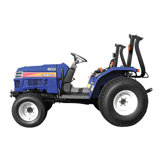
Summary of Contents for Iseki TH4330

  • Page 1: To Our Customer

    ISEKI TRACTORS TO OUR CUSTOMER Thank you very much for purchasing an ISEKI tractor. This operator’s manual provides the information necessary for operating and maintaining your tractor safely and properly. The contents are mainly composed of the following two items:...
  • Page 2: Table Of Contents

    TH4330,4290,4260 TABLE OF CONTENTS TO OUR CUSTOMER ........... 1 TRANSMISSION SHIFT LEVER TABLE OF CONTENTS ..........2 AND CONTROLS (Mechanical Transmission) ..30 TRANSMISSION SHIFT LEVER 1. SAFETY ..............4 AND CONTROLS (Hydrostatic Transmission)..31 PERSONAL SAFETY INSTRUCTIONS ....4 Range Gearshift Lever ........31 MAKING YOUR TRACTOR A SAFE VEHICLE ..
  • Page 3 ISEKI TRACTORS Using Draft Control (Accessory) ......51 ELECTRICAL SYSTEM ...........83 Detaching Implements ........52 CAPACITIES.............83 EXTERNAL AUXILIARY HYDRAULICS TREAD WIDTH SETTING ........83 (ACCESSORY) ............52 MAXIMUM AXLE LOADING ........83 DRAWBAR ...............53 GENERAL DIMENSIONS ........84 ROLL OVER PROTECTIVE STRUCTURE (ROPS) 54 (Mechanical Transmission) How to Tilt ROPS ..........54...
  • Page 4: Safety

    TH4330,4290,4260 SAFETY PERSONAL SAFETY INSTRUCTIONS Whenever you see the words and symbols below, used in this Operator`s Instruction Book and on decals, you MUST take note of their instructions as they relate to personal safety. DANGER: This symbol together with the...
  • Page 5: How To Be A Safe Operator

    SAFETY mind that the implement is wider and may roll easily. If the implement can be folded, fold it beforehand. If there are road or railway crossings where the visibility is poor, you should install on the machine a mirror to give a view ahead of you so that you need not move your machine too far into the intersection.
  • Page 6: Before Operation

    If safety devices are damaged or do no work, please consult your ISEKI dealer. FIG. 1-6 (3) Before removing a safety devices, such as a safety cover, be sure that the machine has stopped com- pletely.
  • Page 7: When Traveling

    SAFETY WHEN TRAVELLING (1) When you travel on roads, ensure the differential lock is off, or the tractor may turn over. (2) Do not make sharp turns when operating at high speed or for transportation as the tractor may turn over.
  • Page 8: Loading Onto Or Unloading From A Truck

    (7) Use ramps with the same or better specifications mentioned below. When the machine is equipped with attachments other than those included in the specifications mentioned below, ask your ISEKI deal- er for advice.
  • Page 9: During Operation

    (5) If you use a trailer, use a proper one which suits your tractor. Using an improper trailer may cause serious accidents. Never attempt to haul beyond the tractor`s capacity. If you have a question, please consult ISEKI dealer. (6) When moving the machine toward an implement for the purpose if installing the implement, never allow any one to stand in between.
  • Page 10: Inspection And Maintenance

    TH4330,4290,4260 INSPECTION AND MAINTENANCE (1) When servicing the tractor or mounting or dismount- ing an implement, place the tractor on level, hard ground which is sufficiently illuminated, or unexpected accidents may occur. (2) When servicing the tractor, follow the instructions list- ed below: •...
  • Page 11: Storage

    Do not attempt to service a tire unless you have the proper equipment and experience to perform the job. Have the work carried out by your ISEKI dealer or a qualified repair service. When seating tire beads onto rims, never exceed the maximum inflation specifications specified on the tire.
  • Page 12: Maintenance Of The Electric System

    TH4330,4290,4260 MAINTENANCE OF THE ELECTRIC SYSTEM TO MAINTENACE ELECTRIC WIRING (1) When servicing the electric wiring, stop the engine without fail. Otherwise your hands or clothes may be caught in or sandwiched between rotating parts. (2) Before manipulating electric parts, be sure to discon- nect the earth battery cable (-), or you may get an electric shock or be injured by sparks.
  • Page 13: To Handle Booster Cable

    SAFETY When disconnecting the battery cables, disconnect the earth cable (-) first without fail. When connecting the bat- tery cables, connect the positive cable (+) first. Disconnecting or connecting in wrong order may lead to a short circuit or sparks. TO HANDLE BOOSTER CABLES When using booster cables, pay attention to the following items for safe operation:...
  • Page 14: Safety Decals And Their Locations

    TH4330,4290,4260 SAFETY DECALS AND THEIR LOCATIONS (5) Ether label (Code No.1674-904-002-1) (1) Fan warning label (Code No. 1705-902-006-0) WARNING: RISK OF EXPLOSION WARNING: RISK OF ENTANGLEMENT Ether or other starting fluid should never be used to Stay clear of the fan while it is running.
  • Page 15 SAFETY (8) Radiator label Take care of handling the battery. (Code No.1674-904-003-0) Improper handling may lead to explosion. Never short the poles. Charge the battery in a well ventilated place. (10) Starter warning label (Code No.1705-902-007-0) WARNING: HIGH PRESSURE STEAM AND HOT WATER Never remove the radiator cap during or just after DANGER: RISK OF ELECTRIC SHOCK...
  • Page 16 TH4330,4290,4260 (12) Fuel label (14) ROPS label (Code No.1705-904-001-0) (Code No.1674-904-005-0) DANGER: RISK OF EXPLOSION AND BURNS Use only diesel fuel. Before replenishing fuel, be sure to stop the engine and wait until the engine and heated parts cool down sufficiently.
  • Page 17 SAFETY LOCATION OF SAFETY DECALS Location of all instruction decals provided as a reference. Replace any decals that are damaged, missing or are not readable. Consult your dealer.
  • Page 18: Introduction

    Tractors. Every effort has been made to provide correct and concise information to you, the operator, as available at date of book publication. Your ISEKI Dealer is available should items in this book or details of your machine not be understood.
  • Page 19: Tractor Identification

    TRACTOR IDENTIFICATION TRACTOR IDENTIFICATION MODEL/SERIAL NUMBERS Each Tractor is identified by means of Tractor model and serial numbers. As a further identification, engine and chassis are provided with identification numbers. To ensure prompt, efficient service when ordering parts or requesting repairs from authorized Dealer, record these numbers in spaces provided.
  • Page 20: Engine Model / Serial Number

    TH4330,4290,4260 ENGINE MODEL NUMBER ENGINE SERIAL NUMBER FIG. 3-3: Engine model number, 1, is cast on right side of engine block, below the injection pump. Engine serial number, 2, is stamped into cylinder block, below engine model number. FIG. 3-3 CHASSIS NUMBER FIG.
  • Page 21: Major Components

    TRACTOR IDENTIFICATION MAJOR COMPONENTS FIG. 3-5: Identification and terminology of major components, as given in this book, are as follows; 1. Front Wheels 11. Reflector / Tail Light 21. Front Axle 2. Fuel Tank Filler 12. Hood 22. Front Axle Pivot 3.
  • Page 22: Instruments & Controls

    TH4330,4290,4260 INSTRUMENTS & CONTROLS FIG. 4-1 (Mechanical Transmission) FIG. 4-1: General layout and location of controls within operator’s area on Tractor. Specific use of these controls is given later in this section and also in “Operation” section of this book: 1.
  • Page 23 12. Hydro Forward Reverse Pedal 5. Front Wheel Drive (4WD) Shift Lever 13. Hand Throttle Lever 6. Slow Lowering Control Knob 14. Brake Pedal 7. Differential Lock Lever 15. Draft Control Lever (Accessory) 8. Hydrostatic Control Lever (TH4330/4290) 16. Auxiliary Hydraulic Valve Controls (Accessory)
  • Page 24: Instrument Panel

    TH4330,4290,4260 INSTRUMENT PANEL FIGS. 4-3, 4-4: Arrangement of gauges, control switches and indicators located in instrument panel. Items are detailed in the descriptions that follow: NOTE: Instrumental panel and switches may vary from those shown. Electric Fuel Shut-Off Turning main switch to off stop will stop engine. This...
  • Page 25: Indicator Light Strip

    INSTRUMENTS & CONTROLS Indicator Light Strip FIG. 4-6: Indicator light strip, 2, contains several warning lights to monitor certain functions. Currently used posi- tions (from left to right) are: Battery Charge - Lights up when main switch is turned "ON" and will go out after engine starts, to indicate bat- tery is being charged.
  • Page 26: Fuel Gauge

    TH4330,4290,4260 Fuel Gauge FIG. 4-9: Gauge, 5, indicates level of diesel fuel in fuel tank when main switch is “ON”. NOTE: Use only clean diesel fuel and clean area to pre- vent dirt/water entry into fuel tank when refilling. DO NOT run out of fuel as bleeding air from the system will be required.
  • Page 27: Power Take-Off (Pto) Switch (Hydrostatic Transmis

    INSTRUMENTS & CONTROLS FIG. 4-13: Turn / hazard indicator lights, 11 and 12, will operate with fender-mounted warning lights. This pro- vides operator with easy indication of warning lights selection. NOTE: Turn lights will not self-cancel. Select turn / haz- ard lights switch to center position after complet- ing turn.
  • Page 28: Main Clutch Pedal

    TH4330,4290,4260 MAIN CLUTCH PEDAL Dual clutch-TH4290/4260 with a mechanical transmis- sion FIG. 4-15: These tractors are equipped with a two stage clutch. Depressing the pedal (1) will reveal two distinct areas of operation made apparent by changes in pedal effort.
  • Page 29: Engine Speed Control

    INSTRUMENTS & CONTROLS Brake Pedal (Hydrostatic Transmission) FIG. 4-17: Brake pedal, 1, control the left and right wheel brakes at the same time. CAUTION: For towing safety, the towed equipment, when fully loaded, should not exceed 1.5 times weight of towing unit. Parking Brake FIG.
  • Page 30: Transmission Controls

    TH4330,4290,4260 TRANSMISSION CONTROLS TRANSMISSION SHIFT LEVER AND CONTROLS (Mechanical Transmission) FIG. 4-20: Two shift levers are used to select ground travel speed through different gear reductions within the drive train. Range shift lever (1) and main gear shift lever (2) are both located to the left of the operator's seat.
  • Page 31: Transmission Shift Lever And Controls (Hydrostatic Transmission)

    Range Gearshift Lever, 1 - Located to the left of the operator’s seat, range lever provides three major speed changes. Hydrostatic Control Lever (TH4330/4290), 2 - Located to left of operator’s seat, this lever actuates hydrostatic control unit for forward travel only. Move lever forward until desired travel speed is reached.
  • Page 32: (Mechanical Transmission)

    TH4330,4290,4260 (Mechanical Transmission) DIFFERENTIAL LOCK PEDAL FIG. 4-25: When differential lock lever, 1, is lowered, both rear axles are locked together to provide equal traction to the both rear wheels. This is especially important when operating in loose soil or slippery condition.
  • Page 33: (Hydrostatic Transmission) Differential Lock Lever

    INSTRUMENTS & CONTROLS (Hydrostatic Transmission) DIFFERENTIAL LOCK LEVER FIG. 4-29: When differential lock lever, 1, is lowered, both rear axles are locked together to provide equal traction to the both rear wheels. This is especially important when operating in loose soil or slippery condition. Disengage differential lock, by releasing lock lever.
  • Page 34: Three-Point Hitch

    TH4330,4290,4260 THREE-POINT HITCH Complete operating instructions for three-point hitch are give in “Operation” section of this book. POSITION CONTROL LEVER FIG. 4-33: Position control lever, 1, adjusts height of three point hitch on rear of Tractor. Setting lever in a par- ticular position will set the height respectively.
  • Page 35: Operation

    OPERATION OPERATION BREAK-IN PERIOD STARTING Pre-Start Inspection Operation of Tractor within the first fifty hours can be a major factor in determining the performance and life of Prior to daily start-up of Tractor, a few basic procedures the engine and Tractor: should be followed to ensure Tractor is in operating order to insure life and dependability: The engine may be operated at full rpm but excessive...
  • Page 36: Normal Starting

    TH4330,4290,4260 Normal Starting CAUTION: Do not attempt to start the tractor unless seated in the operator's seat. Do not allow anyone on the tractor except for the operator. FIG. 5-1, 5-2 & 5-3: To start the engine proceed as fol- lows: 1.
  • Page 37: Restarting Warm Engine

    NOTE: Installation of accessory engine block heater is recommended in cold weather conditions. Consult your ISEKI dealer. IMPORTANT: Under no circumstances should either or other starting fluid be used to start engines equipped with glow plugs. Severe engine damage will result should starting fluid contact a hot glow plug.
  • Page 38: Warm Up Period

    TH4330,4290,4260 Warm Up Period Starting Circuit Operation After starting a cold engine, let engine idle at slow speed Tractor is equipped with a starting system to protect the to make sure all engine components are lubricated. operator. To permit tractor to be started (start motor to...
  • Page 39: Ground Speed Selection (Mechanical Transmission)

    OPERATION GROUND SPEED SELECTION (Mechanical Transmission) FIGS. 5-5& 5-6: These tractors are equipped to provide nine forward gear speeds and three reverse gear speeds. Gear shift lever (1) provides three forward and one reverse gear selection. These gear selections provide a small change in ground speed.
  • Page 40 TH4330,4290,4260 FIGS. 5-8: Arrangenent of gear with appropriate ground speeds, in order from slow to fast, are shown in the chart below. NOTE: Ground speed indicated at 2500 engine rpm. FIG. 5-8...
  • Page 41: Ground Speed Selection (Hydrostatic Transmission)

    IMPORTANT: STOP tractor whenever shifting the range shift lever 1. Hydrostatic control lever (TH4330/4290), 2, is used only forward travel and provides infinitely variable speeds from “0” to top speed in a particular range. This lever allows the operator to set a constant speed for operating in large areas, road travel, etc.
  • Page 42: Stopping Tractor (Hydrostatic Transmission)

    TH4330,4290,4260 STOPPING TRACTOR (Hydrostatic Transmission) FIG. 5-12: To stop Tractor with hydrostatic transmission, move hydrostatic control lever (TH4330/4290), 1, slowly to “0” position, or, if using forward pedal, 2, and lever is located in “0” position, release pedal to stop.
  • Page 43: Four-Wheel Drive

    OPERATION FOUR-WHEEL DRIVE FIGS. 5-16 & 5-17: Four-wheel drive models have a mechanically driven front axle. Engagement and disen- gagement of front drive axle is controlled by lever, 2, at front and below operator’s seat. IMPORTANT: Prior to engaging or disengaging 4WD, Tractor stopped.
  • Page 44: Power Take Off (Pto)

    581 rpm is attained at 2500 engine rpm (TH4260) (Hydrostatic Transmission) 604 / 1092 rpm is attained at 2600 engine rpm (TH4330) 581 / 1050 rpm is attained at 2500 engine rpm (TH4290) 581 / 1050 rpm is attained at 2500 engine rpm (TH4260)
  • Page 45: Mid Pto Shaft

    2000 rpm @ 2500 engine rpm (TH4290) 2000 rpm @ 2500 engine rpm (TH4260) (Hydrostatic Transmission) 2080 rpm @ 2600 engine rpm (TH4330) 2000 rpm @ 2500 engine rpm (TH4290) 2000 rpm @ 2500 engine rpm (TH4260) CAUTION: Make sure all PTO shields are installed on Tractor and equipment.
  • Page 46: Pto Operating Controls (Hydrostatic Transmission)

    TH4330,4290,4260 PTO Operating Controls (Hydrostatic Transmission) FIG. 5-24: PTO and mid PTO are both controlled by PTO control switch, 1. Rear and mid PTO systems can be operated independently of each other. To select rear PTO – Fig. 5-25: Make sure PTO control switch is OFF and then move rear PTO selector lever, 2, rearward to “540rpm”...
  • Page 47: Three-Point Hitch

    OPERATION THREE-POINT HITCH Three-point hitch combines Tractor and implement into one working unit. Implement position and raising are con- trolled hydraulically. In addition, implement weight and loads impose downward pressure at Tractor rear wheels to increase traction. Hitch Controls FIG. 5-27: Control quadrant, to right of operator's seat, controls the system to provide the following hitch control functions: Position Control - Maintains hitch position at constant...
  • Page 48: Rear Linkage

    TH4330,4290,4260 Rear Linkage FIG. 5-29: Linkage consists of several major components for implement attachment and operation: Lower Links, 1 - Primary attaching points to lower imple- ment pins. Lift Rods, 2 - Connect lower links to hydraulic lift arms for raising/lowering of lower links. The lift rod connected to the right lower link has provisions for leveling the implement (side to side).
  • Page 49: Attaching Implements

    OPERATION Attaching Implements CAUTION: Always use POSITION CONTROL to attach / detach implements to provide pre- cise control hitch. FIG. 5-32: Back Tractor to implement, centering Tractor with implement hitch frame. Place draft control lever, 2 (if installed), in fully lowered position as it will not be used. Raise or lower hitch using position control lever, 1, and align left lower link end with corresponding implement attaching pin.
  • Page 50: Using Position Control

    TH4330,4290,4260 Using Position Control Type of Work – Attaching / detaching implements and other operations requiring implement to be kept at con- stant height above ground. Also used with toll bars having flexible row units and implements equipped with gauge (support) wheels.
  • Page 51: Using Draft Control (Accessory)

    OPERATION Using Draft Control (Accessory) Type of Work – When ground-engaging implements such as plows, subsoil’s cultivators, etc. are used. CAUTION: Do not use draft control when pre- cise hitch positioning is required (attaching / detaching implements for example). Using draft control on non-ground engaging imple- ments should not be attempted.
  • Page 52: Detaching Implements

    TH4330,4290,4260 Detaching Implements CAUTION: Always use POSITION CONTROL to attach / detach implements to provide pre- cise control of hitch. Select a level area to detach and store the implement. Lower implement to ground by moving position control lever to DOWN. If necessary, adjust leveling crank on right lift link to level implement on ground.
  • Page 53: Drawbar

    OPERATION FIG. 5-41: Remote couplers are located at rear of Tractor, above three-point hitch. Coupler set, 1, corre- sponds with control lever, 1, (Fig. 5-40), coupler set , 2, with control lever, 2 (Fig. 5-40). Implement hoses must be connected to each coupler set so when respective control lever is pulled rearward, implement raises and when pushed forward, implement lowers.
  • Page 54: Roll Over Protective Structure (Rops)

    TH4330,4290,4260 ROLL OVER PROTECTIVE STRUCTURE (ROPS) Tractor is equipped with fold - down ROPS which can be folded down and the Tractor functionally used in that con- dition for low clearance situation such as orchards, vinevards, barns and chicken houses, etc.
  • Page 55: Lubrication & Periodic Maintenance

    LUBRICATION & PERIODIC MAINTENANCE LUBRICATION & PERIODIC MAINTENANCE SPECIFICATIONS & CAPACITIES Engine Oil Use oil of the quality recommended by ISEKI ; SAE 10W-30, API Service “CC” grade or higher quality. Capacity (Crankcase and Filter) 5.0 liters (TH4330) 3.6 liters (TH4290/4260) Recommended Viscosity: 25˚C and Above...
  • Page 56: Lubrication / Fill Points

    TH4330,4290,4260 LUBRICATION / FILL POINTS (Mechanical Transmission) FIG. 6-1: General layout of lubrication, fill and drain locations on Tractor: Ref. Description Type Crankcase Engine Oil Radiator Engine Coolant Fuel Tank Diesel Fuel Rear Housing Hydraulic Oil Front Axle (4-WD) Hydraulic Oil...
  • Page 57 LUBRICATION & PERIODIC MAINTENANCE LUBRICATION / FILL POINTS (Hydrostatic Transmission) FIG. 6-2: General layout of lubrication, fill and drain locations on Tractor: Ref. Description Type Crankcase Engine Oil Radiator Engine Coolant Fuel Tank Diesel Fuel Rear Housing Hydraulic Oil Front Axle (4-WD) Hydraulic Oil Power Steering Rod Grease...
  • Page 58: Periodic Maintenance Schedule

    TH4330,4290,4260 PERIODIC MAINTENANCE SCHEDULE Recommended Interval, Each: Items marked ( * ) indicate initial service interval only. Subsequent (later) intervals marked “ 0 ” . Intervals above are for normal usage. Severe operating conditions (wet, dusty, etc.), or when previous servicing has indicated need for more...
  • Page 59: Service Access

    LUBRICATION & PERIODIC MAINTENANCE LUBRICATION DETAILS Grease Fittings Lubricate all grease fittings (refer to Fig. 6-1 & 6-2) every 50 hours of operation using No.2 multipurpose lithium- base grease. Clean the grease gun and fittings before and after greasing to prevent contamination from dirt. NOTE: When operating in muddy or extremely wet con- ditions, daily lubrication of fittings is recom- mended.
  • Page 60 TH4330,4290,4260 FIGS. 6-6 & 6-7: To remove front grill; unscrew locking knobs, 4, and pull upward and outward to remove. Disconnect headlights wiring couplers, 5. Reinstall in reverse order making sure front grill lower projections engage on holes. FIG. 6-6...
  • Page 61: Lubrication Details

    LUBRICATION & PERIODIC MAINTENANCE LUBRICATION DETAILS Grease Fittings Lubricate all grease fittings every 50 hours of operation using no. 2 multipurpose lithium base grease. Clean grease gun and fittings before and after greasing to pre- vent contamination from dirt. NOTE: When operating in muddy or extremely wet con- ditions, daily lubrication of fittings is recommend- Engine Oil &...
  • Page 62: Transmission Oil & Filters

    TH4330,4290,4260 Transmission Oil & Filters Transmission oil lubricates transmission, center housing, and rear axles and also serves as hydraulic fluid. Transmission oil and filter should be changed after first 50 hours of operation and then every 200 hours there- after.
  • Page 63: Air Bleeding Hydraulic System

    LUBRICATION & PERIODIC MAINTENANCE Air Bleeding Hydraulic System FIGS. 6-16 & 6-17: When transmission oil has been replaced, it is necessary to bleed the air from the system as follows: Check rear transmission (hydraulic) system oil level and add as necessary. Place a pan under bleed plug, 1.
  • Page 64: Cooling System

    TH4330,4290,4260 COOLING SYSTEM CAUTION: DO NOT remove radiator cap when engine is hot. Rotate cap slowly to release pressure. Then cap can be safely removed. FIG. 6-19: Cooling system is filled at factory with antifreeze solution to protect engine and radiator to –30F (-34C).
  • Page 65: Engine Air Cleaner

    LUBRICATION & PERIODIC MAINTENANCE FIG. 6-22: To adjust belt tension, loosen alternator pivot bolt, 1, and tensioning bracket bolt, 2. Pull out-ward on top of alternator to correctly tension belt and tighten bolt, 2, first and then tighten pivot bolt, 1. IMPORTANT: Do not pry against alternator housing or pulley.
  • Page 66: Fuel System

    / or Tractor warranty void and may cause severe engine damage. Refer to local ISEKI Dealer. Fuel Filter FIG. 6-26: Fuel filter assembly, 1, is located at right side of engine, and is used to strain impurities from fuel before fuel reaches injection pump.
  • Page 67: Air Bleeding Hydraulic System

    LUBRICATION & PERIODIC MAINTENANCE Air-Bleeding Fuel System FIGS. 6-28 & 6-29: Fuel system should be bled of air after the following: Emptied fuel tank. Removal of fuel filter or fuel piping Engine has not run for extended period of time, or, engine starts and stops (or fails to start) after short period of operation.
  • Page 68: Electrical System

    TH4330,4290,4260 ELECTRICAL SYSTEM Battery FIG. 6-31: Battery, 1, is located under engine hood in front of instrument panel. When battery removal, battery condition indicator check- ing or cable cleaning is necessary, open the engine hood. Keep top of battery clean and ensure cable connections are clean and tight.
  • Page 69: To Handle The Battery

    LUBRICATION & PERIODIC MAINTENANCE FIG. 6-33: Water need not be added to battery, the bat- tery is of maintenance-free type. Should battery performance be questioned, the battery should be removed and recharged from an external source following battery charger instructions. Repeated battery charging may be due to a defect in Tractor charg- ing system and/or a defective battery.
  • Page 70: Wiring/Fuse Arrangement

    TH4330,4290,4260 Wiring/Fuse Arrangement CAUTION: Keep all wiring connections clean and tight. Make sure wiring is correctly secured to prevent damage. CAUTION: DO NOT alter wiring by adding "homemade" extensions or replacements. Doing so can eliminate fuse protection and/or eliminate safety features of the system.
  • Page 71 LUBRICATION & PERIODIC MAINTENANCE FIG. 6-34-(1),(2),(3)&(4): General layout and location of electrical system components and fuses: Main Fuse Box, A – Located at right side of engine. FIG. 6-34-(1) FIG. 6-34-(2)
  • Page 72 TH4330,4290,4260 FIG. 6-34-(3) FIG. 6-34-(4)
  • Page 73 IMPORTANT: Fuses are of specific amperage capacity for the circuit in which they are located. Do not replace fuses with unauthorized parts. 7-pin trailer socket, D NOTE: A special fuse is used – use only genuine ISEKI parts.
  • Page 74: Clutch Free-Play Adjustment (Mechanical Transmission)

    TH4330,4290,4260 CLUTCH FREE-PLAY ADJUSTMENT (Mechanical Transmission) FIG. 6-35: Check clutch pedal free-play regularly and adjust as necessary. Correct clutch pedal free-play (A) is 20 to 30 mm (7/8" to 1-1/8") when measured at the end of the pedal as shown (1).
  • Page 75 LUBRICATION & PERIODIC MAINTENANCE BRAKE ADJUSTMENTS (Hydrostatic Transmission) FIG. 6-38: Check free-pedal of brake pedal. Correct free- play, A, is 7/8" to 1-1/8" (20 to 30 mm). NOTE: Through use, free-play will increase and brake balance will be affected. Adjust and balance brakes before free-play is excessive FIG.
  • Page 76: Hydrostatic Adjustments

    TH4330,4290,4260 HYDROSTATIC ADJUSTMENTS For adjustments of the hydrostatic linkage, see your deal- WHEELS & TIRES Examine wheels and tires periodically for correct inflation pressures, tight wheel bolts, and any physical damage that may be a detriment to Tractor operation and operator safety.
  • Page 77: Front Wheel Spacing

    LUBRICATION & PERIODIC MAINTENANCE Front Wheel Spacing Tread width may be varied by using the following meth- ods, as applicable. Tread widths are measured tire center to tire center as close to the ground as possible. NOTE: Make certain desired setting is compatible with implements to be used to prevent clearance and interference problem.
  • Page 78: Steering Free-Play

    TH4330,4290,4260 Steering Free-Play FIG. 6-46: Steering should be checked for excessive looseness, as indicated by steering wheel free- play. Maximum free-play is approximately 1-1/4" to 2-3/8” (30 to 60 mm) when measured at outside of steering wheel rim, as shown at “X”. Excessive free-play can be caused ·...
  • Page 79: Storage

    LUBRICATION & PERIODIC MAINTENANCE STORAGE FIG. 6-50: If Tractor is to be stored for extended periods, such as off-season nonuse, certain measures should be taken for its preservation during such periods. These measures will vary according to geographicat area and storage season.
  • Page 80: Troubleshooting

    TH4330,4290,4260 TROUBLESHOOTING ENGINE Problem Possible Cause Remedy Starter motor does not Range shift lever not in neutral Place range shift lever in neutral. operate with key turned to PTO control switch is in ON position Turn off PTO control switch.
  • Page 81: Brake

    TROUBLESHOOTING BRAKE Problem Possible Cause Remedy Brake do not work well or not balanced Too much free play of pedal Adjust free play Worn or seized lining Consult your dealer. Brake pedal do not return Broken return springs Replace broken spring. smoothly Poor lubrication Remove rust, then lubricate.
  • Page 82: Specifications

    TH4330,4290,4260 SPECIFICATIONS HYDROSTATIC TRANSMISSION MODEL: TH4260FH TH4290FH TH4330FH SUB MODEL: MRE / ME MRE / ME MRE / ME ENGINE: Make Iseki Diesel Model E3CE-VB11 E3CF-VB22 E3CD-VB32 Type Indirect injection, overhead valve Aspiration Natural Displacement 1430 cc 1463 cc 1498 cc...
  • Page 83: Electrical System

    SPECIFICATIONS MODEL: TH4260FH TH4290FH TH4330FH ELECTRICAL SYSTEM: System Voltage 12 volt, negative (-) ground Battery cca @ 0 F (-18) 582 cca Charging 40 amp alternator with internal regulator/rectifier CAPACITIES: Engine Crankcase with Filter 3.6 liters 4.4 liters Transmission 29.0 liters Fuel Tank 23 liters 30 liters...
  • Page 84: General Dimensions

    TH4330,4290,4260...
  • Page 85: (Mechanical Transmission) Engine

    SPECIFICATIONS MECHANICAL TRANSMISSION MODEL: TH4260F TH4290F SUB MODEL: MDRE / MDE MDRE / MDE ENGINE: Make Iseki Diesel Model E3CE-VB12 E3CF-VB24 Type Indirect injection, overhead valve Aspiration Natural Displacement 1430 cc 1463 cc Number of Cylinders Bore 85 mm 86 mm...
  • Page 86: Electrical System

    TH4330,4290,4260 MODEL: TH4260F TH4290F ELECTRICAL SYSTEM: System Voltage 12 volt, negative (-) ground Battery cca @ 0 F (-18) 433 cca Charging 40 amp alternator with internal regulator/rectifier CAPACITIES: Engine Crankcase with Filter 3.6 liters Transmission 29.0 liters Fuel Tank...
  • Page 87: General Dimensions

    SPECIFICATIONS...
  • Page 88: Assembly & Pre-Delivery Inspection

    TH4330,4290,4260 ASSEMBLY & PRE-DELIVERY INSPECTION ASSEMBLY 1. Remove wheels, fenders, and sundry boxes from container. IMPORTANT: Do not commence assembly of this Tractor until reading these instructions 2. Disassemble container. completely and carefully. 3. Inspect Tractor for damage and any evidence of NOTE: For certain lubrication, adjustments, etc., refer to...
  • Page 89 ASSEMBLY & PRE-DELIVERY INSPECTION 7. Front Bumper – Install front bumper and secure with IMPORTANT: Bolts should be installed with heads to out- four bolts supplied in sundry box. side (nuts on inside) of lift link, to prevent tire interference during operation. 8.
  • Page 90: Pre-Delivery Inspection

    TH4330,4290,4260 PRE-DELIVERY INSPECTION Check that engine oil level is correct. Turn main switch to “START” to crank the engine. Release key to “ON” position the moment engine Check that coolant level is correct. starts. Check that warning lights go out.
  • Page 91 ISEKI TRACTOR...
  • Page 92 TH4330,4290,4260...
  • Page 93 WIRING DIAGRAM WIRING DIAGRAM WIRING DIAGRAM TH4260F...
  • Page 94 WIRING DIAGRAM TH4260FH...
  • Page 95 WIRING DIAGRAM TH4290F...
  • Page 96 TH4330,4290,4260 WIRING DIAGRAM TH4290FH & 4330FH...

This manual is also suitable for:

Th4290Th4260

Table of Contents