Table of Contents

Subscribe to Our Youtube Channel
Related Manuals for Panasonic MC-GG523-00


Summary of Contents for Panasonic MC-GG523-00
-
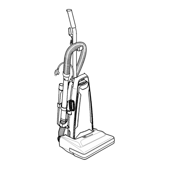
Page 1: Vacuum Cleaner
Order Number MAC1203001CE Vacuum Cleaner MC-GG523-00 Specifications are subject to change without notice for further improvement. © 2012 PANASONIC CONSUMER ELECTRONICS COMPANY, DIVISION PANASONIC CORPORATION OF NORTH AMERICA. All rights... -
Page 2: Table Of Contents
MC-GG523-00 CONTENTS Page Page 1 WIRING DIAGRAM AND DRAWING 3.1. Fan Motor 1.1. Wiring Diagram 3.2. Power Cord / On-Off Switch Replacement 1.2. Wire Management Drawing 4 SERVICE PROCEDURES - NOZZLE 2 EXPLODED VIEW AND PARTS LIST 4.1. Lower Plate 2.1. -
Page 3: Wiring Diagram And Drawing
MC-GG523-00 1 WIRING DIAGRAM AND DRAWING 1.1. Wiring Diagram... -
Page 4: Wire Management Drawing
MC-GG523-00 1.2. Wire Management Drawing NOTE: For general servicing, it is necessary to eliminate pinching of any wire during reassembly. After servicing any electrical component or electrical enclosure, the unit should be reassembled and checked for dielectric breakdown or current leakage. -
Page 5: Exploded View And Parts List
MC-GG523-00 2 EXPLODED VIEW AND PARTS LIST 2.1. Body - Front 2.1.1. Exploded View... -
Page 6: Parts List
MC-GG523-00 2.1.2. Parts List Ref. No. Part No. Part Name & Description Qty. Remarks AC88KDKCZV07 DUST COMPARTMENT UNIT AC98EARFZ0U ON/OFF SWITCH AMC-1CTCE23 WIRE CONNECTOR AC66KV01V06 PACKING (DUST CONTAINER) AC80FDTBZY02 SWITCH COVER ASSEMBLY AMC73K-V0ZV006 PACKING (SWITCH COVER) AXTN4+20BFY HANDLE SCREW AMC73B-V00... -
Page 7: Nozzle Housing
MC-GG523-00 2.2. Nozzle Housing 2.2.1. Exploded View... - Page 8 MC-GG523-00 2.2.2. Parts List Ref. No. Part No. Part Name & Description Quantity Remarks AC01ADUSZUU3 NOZZLE HOUSING AC91AAEZZV07 LOWER PLATE UNIT AC27AAEZZV07 LOWER PLATE COMPLETE AC06AAJUZ00 BODY LOWER PLATE ASSY. AXTN4+16BFY SCREW AC19AARKZV00 BODY PACKING AMC43S-V00 BELT COVER AC68ACUTZ000 SCREW...
-
Page 9: Packing Materials
MC-GG523-00 2.3. Packing Materials 2.3.1. Exploded View 2.3.2. Parts List (Packing Material) Ref. No Part No. Part Name & Description Quantity Remarks AC61ZDUVZ000 INDIVIDUAL CARTON AC01ZDUSZ000 OPERATING INSTRUCTIONS AC94ZDUSZ000 PACKING ASSEMBLY... -
Page 10: Service Procedures - Body
MC-GG523-00 3 SERVICE PROCEDURES - BODY 3.1. Fan Motor 3. Wrap noise suppressor around the motor. 4. Reinstall motor into into the dust compartment with the tabs 3.1.1. Removal on the motor support rear aligned parallel to the front edge of the dust compartment. -
Page 11: Power Cord / On-Off Switch Replacement
MC-GG523-00 3.2. Power Cord / On-Off Switch Replacement 3.2.1. Removal 1. Remove the dust cover and switch cover to expose the electrical connections of the power cord, on-off switch and wire cord. 2. Remove the flat washer and cord retainer. Remove the wire connections, and wire tie, if present. -
Page 12: Service Procedures - Nozzle
MC-GG523-00 4 SERVICE PROCEDURES - NOZZLE 4.1. Lower Plate 4.1.1. Removal 1. Place handle in low position. 2. Turn the vacuum cleaner over exposing the underside. Release the lower plate by pressing the two (2) latches that secure it inward. -
Page 13: Belt Replacement
MC-GG523-00 4. Insert a flat blade screwdriver between the nozzle housing 2. Start the new agitator assembly back into the nozzle and the plastic shaft. Pry out the plastic shaft as illustrated. housing by placing the side opposite the belt partially into the slot. - Page 14 MC-GG523-00 4. Install the belt, agitator assembly, and the lower plate according to the respective instructions.
Need help?
Do you have a question about the MC-GG523-00 and is the answer not in the manual?
Questions and answers