Table of Contents
Advertisement
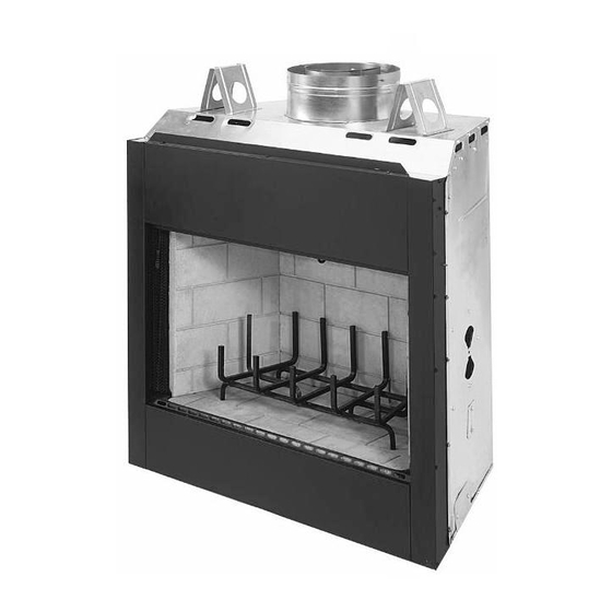
INSTALLATION
INSTRUCTIONS
42" Wood Burning Fireplaces
P/N 850,047M REV. B 12/2008
MODELS
RDI-42
RDI-42-H
This installation manual will enable you to obtain a safe, efficient and
dependable installation of your fireplace system. Please read and under-
stand these instructions before beginning your installation.
Do not alter or modify the fireplace or its components under any
circumstances. Any modification or alteration of the fireplace system,
including but not limited to the fireplace, chimney components and
accessories, may void the warranty, listings and approvals of this system
and could result in an unsafe and potentially dangerous installation.
IMPORTANT! TO ASSURE PROPER ALIGNMENT OF GLASS DOORS:
INSTALL THIS FIREPLACE IN A SQUARE AND PLUMB CONDITION,
USING SHIMS AS NECESSARY AT SIDES AND/OR BOTTOM.
INSTALLER: Leave this manual with the appliance.
CONSUMER: Retain this manual for future reference.
NOTE: DIAGRAMS & ILLUSTRATIONS NOT TO SCALE.
®
MERIT
SERIES
HCI-42
HCI-42-H
Portland
OMNI Report No. 116-F-52-2
US
1
Advertisement
Table of Contents

Subscribe to Our Youtube Channel
Related Manuals for Lennox Hearth Products HCI-42


Summary of Contents for Lennox Hearth Products HCI-42
- Page 1 INSTALL THIS FIREPLACE IN A SQUARE AND PLUMB CONDITION, USING SHIMS AS NECESSARY AT SIDES AND/OR BOTTOM. INSTALLER: Leave this manual with the appliance. CONSUMER: Retain this manual for future reference. NOTE: DIAGRAMS & ILLUSTRATIONS NOT TO SCALE. ® SERIES HCI-42 HCI-42-H Portland OMNI Report No. 116-F-52-2...
-
Page 2: Table Of Contents
TABLE OF CONTENTS Safety Rules ... page 2 Tools and Building Supplies ... page 2 Precautions ... page 3 Introduction ... page 3 Clearances/Height Requirements ... page 3 Chimney System ... page 3 Assembly Outline ... page 4 Location of Fireplace ... page 4 Assembly Steps ... -
Page 3: Precautions
PRECAUTIONS Note: These fireplace systems are not difficult to install. However, in the interest of safety, it is recommended that the installer be a qualified or certified “tradesman” familiar with commonly accepted fireplace installation and safety tech- niques as well as prevailing local codes. The most important areas of concern dealing with the installation of factory-built fireplaces are clearances to combustible materials, proper as-... -
Page 4: Assembly Outline
Insulate Joists Same As Ceiling Draft Stops Firestop CTDT Termination Note: Non- Combustible Chase Flashing Must Be Used To Cover Chase Opening Level Solid Continuous Surface Insulation (Thermal Barrier) Figure 2 WARNING: IF INSULATION IS USED, THE FIREPLACE MUST NOT BE PLACED DI- RECTLY AGAINST IT. -
Page 5: Assembly Steps
ASSEMBLY STEPS Note: The following steps represent the normal sequence of installation. Each installation is unique, however, and might require a different sequence. 1. Position firebox prior to framing or into prepared framing. 2. Install the chimney system. 3. Connect house wiring to the fireplace for later attachment of optional blower. -
Page 6: Fireplace Specifications
1-1/2" Metal Safety Strips Figure 8 Metal Safety Strips Figure 9 Step 3. Refer to fireplace drawings and specifi- cations on pages 6 and 7 for framing dimensions and details. Frame appliance enclosure as illus- trated in Figures 11 through 14 on page 8. IMPORTANT: UNDER NO CIRCUMSTANCES CAN THE FIREPLACE TOP SPACERS ( FIGURE 10 ) BE REMOVED OR MODIFIED, NOR MAY... -
Page 7: Framing Specifications
FRAMING SPECIFICATIONS Header Fireplace Framing Figure 11 Back Wall of Chase/Enclosure FOAK Combustion Including Finising Materials if any Air Kit Framing Face Inside Chase (Unfinished Shown) Figure 12 Back Wall of Chase/Enclosure FOAK Including Finising Materials Combustion if any Air Kit - Optional Rough Framing Face (Unfinished Shown) -
Page 8: Installing The Chimney System
Step 4. Fireplace should be secured to side framing members using the nailing tabs at the top and bottom of the fireplace front face. Use 8d nails or equivalent ( Figure 17 ). 8d Nail Or Equivalent Figure 17 Note: The nailing tabs and the area directly behind the nailing tabs are exempt from the clearances described on page 5. -
Page 9: Offset Through Floor/Ceiling
CHIMNEY 30 OFFSET THROUGH FLOOR OR CEILING It may be necessary to assemble the chimney at 30 when passing through the floor or ceiling area. Use the F8FS30-2 firestop spacer as shown in Figures 22 and 23 . Support the chimney at floor or ceiling penetration with a FTF8 stabilizer if distance of chimney below ceiling is 10' or more. - Page 10 Note: Do not apply excessive pressure to any subsequent chimney sections following the stabilizer when installing. Ensure each subse- quent chimney section is securely attached by testing as noted in Step 4. Step 6. Select the proper Security roof flash- ing based on pitch of roof.
-
Page 11: Ten Foot Rule Summary
Less Than 10' Figure 34 Note: It is recommended that all exterior ex- posed metal fireplace components; such as terminations, flashings, storm collars and/or flue be painted with a premium quality, high temperature, rust preventative paint designed for metal. This is especially important when installations are made in abnormally adverse or corrosive environments;... -
Page 12: Vertical Elevation Chart
The offset and return elbows may be attached together, or a section or sections of chimney may be used between, but do not exceed 20' in total length between elbows. If sections of pipe exceed 10' between elbows, a chimney stabi- lizer must be used at the midpoint ( Figure 36 ). -
Page 13: Offset Elevation Chart
Return Elbow Max. Stabilizer 10' Max. Offset Elbow Figure 36 Figure 37 OFFSET ELEVATION CHART FTF8-ES30 Offset Height Offset/Return FTF8-S4 (Inches) (Inches) Elbow Stabilizer NOTE: DIAGRAMS & ILLUSTRATIONS NOT TO SCALE. Number of FTF8 Chimney Sections 12" 18" 36" 48"... -
Page 14: Installing Offsets
Joints Chimney Section No. 8 x 1/2" SMS Figure 38 Underside Of Chimney Figure 39 FTF8-E30 Return Elbow* Chimney Section (S) FTF8-30 Offset Elbow* *Part of Offset/Return Package Model FTF8-ES30 Figure 40 INSTALLING OFFSETS First, review the Offset Elevation Chart and Figure 38 for reference. -
Page 15: Combustion Air Kits
POWER TO THE FIREPLACE The Optional Blower Kit Operates on 115 volt 60 Hz 150 watts AC HOUSE WIRING GROUND WIRE COVER PLATE Replace Cover Plate House Wiring Must Be Secured With The Appropriate Electrical After Electrical Connector To The Fireplace Hook-Up Convenience Outlet Wiring Figure 42... -
Page 16: Glass Doors
If you’re installing a gas line, connect it before the fireplace is framed and enclosed in the finished wall. The gas knockout is determined by the indentation located at the bottom and slightly off center in the side refractories. THE KNOCKOUT IS ALWAYS REMOVED FROM IN- SIDE THE FIREPLACE. - Page 17 Hearth Extension Dimensions 16" 38" 8" 54" Note: To convert inches to millimeters divide by 0.03937 Figure 47 Methods of Determini ng Hearth Extension and Wall Shield Equivalents - To determine the thickness required for the alternate material when either the “k” value or “r” value is known, use either the k formula or r formula.
-
Page 18: Finish To Your Taste
Wall Shield Required Where Less Than 12" 36" 36" Figure 48 Calculating Minimum Thickness if Multiple Materials are Used At times it is important to know what combination of materials are acceptable for use as floor protection. The “R values” are used to determine acceptable combinations of materials because “R values”... -
Page 19: Installation Components
INSTALLATION COMPONENTS The following items are available for use in the installation of this appliance. Firestop Spacer (30 ) 63L32 F8FS30-2 Offset/ Return Package (30 ) 63L22 FTF8-ES30 Stabilizer 63L25 FTF8-S4 Firestop Spacer (Flat) 63L31 F8FS-2 Storm Collar 63L59 Shipping Weight 188 lbs. - Page 20 The manufacturer reserves the right to make changes at any time, without notice, in design, materials, specifications, prices and also to discontinue colors, styles and products. Consult your local distributor for fireplace code information. Printed in U.S.A. © 2007 by LENNOX HEARTH PRODUCTS P/N 850,047M REV. A 12/2008...
Need help?
Do you have a question about the HCI-42 and is the answer not in the manual?
Questions and answers