Pioneer DEH-P440 Service Manual

Pioneer DEH-P440 Service Manual

Multi-cd control high power cd playre with fm/am tuner

Advertisement

Service
Manual
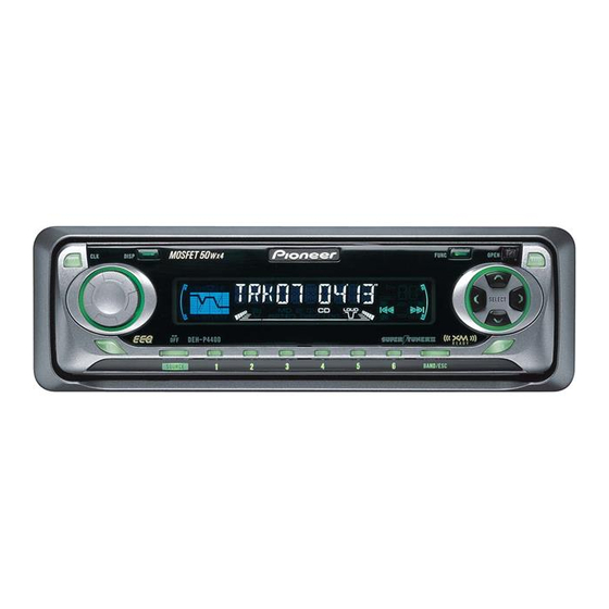
MULTI-CD CONTROL HIGH POWER CD PLAYRE WITH FM/AM TUNER
DEH-P440
DEH-P4400
DEH-P440
This service manual should be used together with the following manual(s):
Model No.
Order No.
CX-977
CRT2624
CONTENTS
1.SAFETY INFORMATION . . . . . . . . . . . . . . . . . . . . 3
2.EXPLODED VIEWS AND PARTS LIST . . . . . . . . . . . . . 4
4.PCB CONNECTION DIAGRAM . . . . . . . . . . . . . . . . . . 26
5.ELECTRICAL PARTS LIST . . . . . . . . . . . . . . . . . . . . . . 34
6.ADJUSTMENT. . . . . . . . . . . . . . . . . . . . . . . . . . . . . . . . 40
7.GENERAL INFORMATION . . . . . . . . . . . . . . . . . . . . . . 48
7.1 DIAGNOSIS . . . . . . . . . . . . . . . . . . . . . . . . . . . . . . . 48
For details, refer to "Important symbols for good services" on the next page.
PIONEER CORPORATION
PIONEER ELECTRONICS (USA) INC.
PIONEER EUROPE NV
Haven 1087 Keetberglaan 1, 9120 Melsele, Belgium
PIONEER ELECTRONICS ASIACENTRE PTE.LTD. 253 Alexandra Road, #04-01, Singapore 159936
C PIONEER CORPORATION 2001
EQ
DEH-P440/XN/UC
/XN/UC
/XN/UC
Mech.Module
S9
CD Mech. Module:Circuit Description,Mech. Description,Disassembly
4-1, Meguro 1-Chome, Meguro-ku, Tokyo 153-8654, Japan
P.O.Box 1760, Long Beach, CA 90801-1760 U.S.A.
AUDIO
SELECT
SFEQ
/XN/UC
/XN/UC
Remarks
7.1.1 DISASSEMBLY . . . . . . . . . . . . . . . . . . . . . . . . . . .48
7.2 PARTS . . . . . . . . . . . . . . . . . . . . . . . . . . . . . . . . . . . .52
7.2.1 IC . . . . . . . . . . . . . . . . . . . . . . . . . . . . . . . . . . . . .52
7.2.2 DISPLAY . . . . . . . . . . . . . . . . . . . . . . . . . . . . . . . .62
7.3 OPERATION FLOW CHART . . . . . . . . . . . . . . . . . . .63
7.4CLEANING . . . . . . . . . . . . . . . . . . . . . . . . . . . . . . . . .64
8. OPERATIONS AND SPECIFICATIONS . . . . . . . . . . . .65
ORDER NO.
CRT2771
K-ZZU2000.printed in Japan
K-ZZU.2001.printed in Japan

Advertisement

Table of Contents
loading

Summary of Contents for Pioneer DEH-P440

  • Page 1: Table Of Contents

    PIONEER ELECTRONICS (USA) INC. P.O.Box 1760, Long Beach, CA 90801-1760 U.S.A. PIONEER EUROPE NV Haven 1087 Keetberglaan 1, 9120 Melsele, Belgium PIONEER ELECTRONICS ASIACENTRE PTE.LTD. 253 Alexandra Road, #04-01, Singapore 159936 C PIONEER CORPORATION 2001 K-ZZU2000.printed in Japan K-ZZU.2001.printed in Japan...
  • Page 2 However grating of the pickup unit can be by a jumper-solder). confirmed. 2. During disassembly, be sure to turn the power off since an internal IC might be destroyed when a con- nector is plugged or unplugged. DEH-P440/XN/UC...
  • Page 3: Safety Information

    WARNING This product contains lead in solder and certain electrical parts contain chemicals which are known to the state of California to cause cancer, birth defects or other reproductive harm. Health & Safety Code Section 25249.6 - Proposition 65 DEH-P440/XN/UC...
  • Page 4: Exploded Views And Parts List

    • For the applying amount of lobricants or glue, follow the instructions in this manual. (In the case of no amount instructions,apply as you think it appropriate.) 2.1 PACKING PACKING PARTS LIST Symbol and Mark DEH-P440/XN/UC DEH-P4400/XN/UC DEH-P44/XN/UC Description Owner's Manual CRD3542...
  • Page 5 Symbol and Mark DEH-P440/XN/UC DEH-P4400/XN/UC DEH-P44/XN/UC Description Screw CRZ50P090FMC CRZ50P090FMC CRZ50P090FMC Screw TRZ50P080FMC TRZ50P080FMC TRZ50P080FMC Polyethylene Bag CEG-158 CEG-158 CEG-158 Handle CNC5395 CNC5395 CNC5395 Bush CNV3930 CNV3930 CNV3930 Polyethylene Bag CEG1173 CEG1173 CEG1173 Carton CHG4557 CHG4553 CHG4556 Contain Box CHL4557...
  • Page 6 2.2 EXTERIOR DEH-P440/XN/UC...
  • Page 7 CNC9096 84 Cover CNS7068 39 Cover CNM6854 40 Panel CNS6278 85 Clamper CEF1007 86 Connector(CN701) CKS3408 41 Pin CNV6486 87 Connector(CN331) CKS3598 42 Lighting Conductor CNV6487 88 Spring CBL1470 43 Gear CNV6507 44 Arm CNV6508 45 Panel Unit CWM7375 DEH-P440/XN/UC...
  • Page 8 (2) CONTRAST TABLE DEH-P440/XN/UC, DEH-P4400/XN/UC and DEH-P44/XN/UC are constructed the same except for the following: Symbol and Mark DEH-P440/XN/UC DEH-P4400/XN/UC DEH-P44/XN/UC Description Tuner Amp Unit CWM8015 CWM8014 CWM8014 Detach Grille Assy CXB8406 CXB8407 CXB8408 Knob CAA2725 CAA2699 CAA2699 Keyboard Unit...
  • Page 9 DEH-P440/XN/UC...
  • Page 10: Cd Mechanism Module

    2.3 CD MECHANISM MODULE DEH-P440/XN/UC...
  • Page 11 38 Bracket CNC9123 84 Roller CNV6887 39 Frame CNC9656 85 Spring CBH2509 40 Belt CNT1086 86 Spring CBH2512 41 Gear CNV6886 87 Spring CBH2536 42 Gear CNV6316 88 Collar CNV6906 43 Gear CNV6317 44 Gear CNV6318 45 Gear CNV6319 DEH-P440/XN/UC...
  • Page 12: Block Diagram And Schematic Diagram

    HOME 12EJ DISC +5V REGULATOR SENSE 8EJ SENSE CLAMP SENSE SENSE IC 701 BA05SFP Q511 CN750 CN1950 Q751 CD5VON ILB+ Q753 CSENS EJECT FILM+ S750 SW5V Q750 DETACH SENSE SW Q752 FILM– DPDT KYDT Q754 ROT1 ROT0 BL+B Q755 DEH-P440/XN/UC...
  • Page 13: Panel Unit

    OPT IN FILM+ RS-140 S750 SW5V SW5V Q750 DETACH ENSE SW FILM– DPDT DPDT KEY MATRIX DPDT KYDT KYDT LCD DRIVER KYDT KEY DATA S1922 IC 1903 ROT1 RDT1 PD6294A X1901 ROT0 RDT0 LCD DATA Q1905 DIMMER BL+B BL+B DEH-P440/XN/UC...
  • Page 14 Note: When ordering service parts, be sure to refer to " EXPLODED VIEWS AND PARTS LIST" or "ELECTRICAL PARTS LIST". Large size SCH diagram Guide page Detailed page P4400,P44 PE5246A DSP-201M SYSTEM CONTROLLER DETACH SENSE S EJECT PANEL UNIT CD:+4.1dBs The > mark fo the importance Therefore, whe identical desig DEH-P440/XN/UC...
  • Page 15 12k ohms 10k ohms *Capacitors Code Practical value The > mark found on some component parts indicates 0.01uF the importance of the safety factor of the part. 101/10 100uF/10V Therefore, when replacing, be sure to use parts of identical designation. DEH-P440/XN/UC...
  • Page 16 DEH-P440/XN/UC...
  • Page 17 DEH-P440/XN/UC...
  • Page 18 DEH-P440/XN/UC...
  • Page 19 DEH-P440/XN/UC...
  • Page 20 3.3 KEYBOARD UNIT Model DEH-P440/XN/UC S1902, CSG1107 DEH-P4400/XN/UC S1904,S1906, S1909-S1919 CSG1117 DEH-P44/XN/UC Model DEH-P440/XN/UC CSG1107 DEH-P4400/XN/UC S1901,S1907 CSG1133 DEH-P44/XN/UC Model DEH-P440/XN/UC DEH-P4400/XN/UC DEH-P44/XN/UC DEH-P440/XN/UC...
  • Page 21 KEYBOARD UNIT CSG1111 DEH-P440/XN/UC...
  • Page 22 S901 : HO S902 : CLA S903 : DS S904 : 12E S905 : 8EJ The under SPINDLE NOTE : Symbol indicate No differentiatio M1 CXB6007 discrete resistors Symbol indicate LOADING/CARRIAGE No differentiatio discrete capacito M2 CXB5903 5V REGULATOR DEH-P440/XN/UC...
  • Page 23 Decimal points for resistor No differentiation is made between chip resistors and and capacitor fixed values discrete resistors. are expressed as : Symbol indicates a capacitor. ← ← No differentiation is made between chip capacitors and 0.022 R022 discrete capacitors. CN701 CN501 DEH-P440/XN/UC...
  • Page 24 10µs/div. % CH1:RFO 0.5µs/div. % CH1:RFO 7 CH1:MD 500mV/div. 500mV/div. 500mV/div. 2ms/div. 0 CH2:TE 500mV/div. During "Play" During "Play" During "Tracking Open" Ref. : Ref. : Ref. : VREF VREF VREF Mode : Mode : Mode : Normal Normal Test DEH-P440/XN/UC...
  • Page 25 When "Eject" (8cm CD) When "Eject" (12 cm CD) Ref. : Ref. : Ref. : VREF Mode : Mode : Mode : Normal Normal Normal ) CH1:LOUT 2V/div. 200µs/div. ⁄ CH2:ROUT 2V/div. "Play" in 1kHz, 0dB Ref. : Mode : Normal DEH-P440/XN/UC...
  • Page 26: Pcb Connection Diagram

    For further information for respective destinations, be sure to check with the schematic dia- gram. 2.Viewpoint of PCB diagrams Capacitor Connector SIDE A SIDE B P.C.Board Chip Part DETACH SENSE SW CN701 DEH-P440/XN/UC...
  • Page 27 SIDE A REAR OUTPUT IP-BUS INPUT ANTENNA JACK CORD ASSY CN1950 FRONT DEH-P440/XN/UC...
  • Page 28 TUNER AMP UNIT DEH-P440/XN/UC...
  • Page 29 SIDE B DEH-P440/XN/UC...
  • Page 30 4.2 PANEL UNIT SIDE A SIDE B PANEL UNIT PANEL UNIT EJECT CN750 CN1901 DEH-P440/XN/UC...
  • Page 31 4.3 KEYBOARD UNIT SIDE A SIDE B KEYBOARD UNIT KEYBOARD UNIT VOLUME DISPLAY SOURCE BAND CN1951 FUNCTION AUDIO DEH-P440/XN/UC...
  • Page 32 4.4 CD MECHANISM MODULE CONTROL UNIT SIDE A DSCSNS 12EJ CN501 HOME DEH-P440/XN/UC...
  • Page 33 CONTROL UNIT SIDE B CLAMP DEH-P440/XN/UC...
  • Page 34: Electrical Parts List

    Circuit Symboland No. Part Name Parts No. Circuit Symboland No. Part Name Parts No. Diode HZS9L(B1) Diode 1SS270 Diode 1SS270 Diode DAP202U Diode DAN202U Diode DAP202K Unit Number:CWM8015(DEH-P440) Diode DAN202K Diode DAN202U :CWM8014(DEH-P4400,P44) Diode DAP202U Diode HZS9L(B3) Unit Name:Tuner Amp Unit Diode HZS6L(B2) MISCELLANEOUS...
  • Page 35 Circuit Symboland No. Part Name Parts No. Circuit Symboland No. Part Name Parts No. (DEH-P440) RS1/16S821J (DEH-P4400,P44) RS1/16S473J RS1/16S223J RS1/16S2202F RS1/16S821J RS1/16S102J RS1/16S821J RS1/16S821J RS1/16S223J RS1/16S102J RS1/16S821J RS1/16S0R0J (DEH-P4400,P44) RS1/16S821J RS1/16S473J RS1/16S223J RS1/16S0R0J RS1/16S223J RS1/16S101J RS1/16S103J RS1/16S104J RS1/16S103J RS1/16S0R0J RS1/16S331J...
  • Page 36 CKSRYB103K50 CEJA1R0M50 CCSRCH101J50 CEJA1R0M50 CCSRCH101J50 CKSRYB105K6R3 CKSRYB103K50 CKSRYB105K6R3 CKSRYB472K50 CKSRYB104K16 CKSRYB104K16 CKSRYB104K16 CKSRYB105K6R3 CKSRYB473K16 CKSRYB105K6R3 CEJA1R0M50 CKSRYB105K6R3 CEJA1R0M50 CEJA1R0M50 CKSRYB105K6R3 (DEH-P440) CKSRYB105K6R3 CEJA1R0M50 (DEH-P440) CKSRYB105K6R3 CKSRYB103K25 (DEH-P440) CKSRYB103K50 CKSQYB104K16 CKSRYB102K50 CKSQYB103K50 CKSQYB473K16 CEJA100M16 CKSRYB104K16 330µF/16V CCH1326 CEJA470M10 CKSRYB103K25 (DEH-P440) CEJA2R2M50...
  • Page 37 Circuit Symboland No. Part Name Parts No. 1914 Switch(DEH-P440,P4400) CSG1107 1914 Switch(DEH-P44) CSG1117 1915 Switch(DEH-P440,P4400) CSG1107 1915 Switch(DEH-P44) CSG1117 1916 Switch(DEH-P440,P4400) CSG1107 Unit Number:CWM8308(DEH-P440,P4400) 1916 Switch(DEH-P44) CSG1117 :CWM8310(DEH-P44) 1917 Switch(DEH-P440,P4400) CSG1107 1917 Switch(DEH-P44) CSG1117 Unit Name:Keyboard Unit 1918 Switch(DEH-P440,P4400) CSG1107 1918...
  • Page 38 CKSRYB104K16 RS1/8S120J CKSRYB105K6R3 RS1/8S100J CKSRYB104K16 RS1/16S513J CCSRCH560J50 RS1/16S513J CKSRYB224K16 RS1/16S823J CKSRYB224K16 RS1/16S823J CKSRYB273K25 RS1/16S823J CKSRYB273K25 RS1/16S124J CKSRYB104K16 RS1/16S183J CKSRYB104K16 RS1/16S153J CCSRCK2R0C50 RS1/16S103J CCSRCH220J50 RS1/16S103J CKSRYB153K25 RS1/16S124J CKSRYB104K16 RS1/16S0R0J CKSRYB103K50 RS1/16S471J CKSRYB103K50 RS1/16S333J CKSRYB104K16 RS1/16S332J CKSRYB104K16 RS1/16S332J CKSRYB333K16 RS1/16S514J CKSRYB104K16 DEH-P440/XN/UC...
  • Page 39 Circuit Symboland No. Part Name Parts No. CKSRYB473K16 CKSRYB473K16 CKSRYB104K16 CKSRYB104K16 CEV220M6R3 CKSRYB104K16 CKSRYB104K16 CKSRYB104K16 CCSRCH470J50 CKSRYB471K50 CKSRYB472K50 CKSRYB104K16 CKSRYB104K16 CKSRYB104K16 CKSRYB221K50 CKSRYB221K50 CKSRYB153K25 CKSRYB103K50 CEV101M10 CKSRYB104K16 CKSRYB104K16 10µF/10V CCH1349 CEV101M10 CKSRYB224K16 Miscellaneous Parts List Pickup Unit(Service)(P9) CXX1480 Motor Unit(SPINDLE) CXB6007 Motor Unit(LOADING/CARRIAGE)CXB5903 DEH-P440/XN/UC...
  • Page 40: Adjustment

    • This equipment will not guarantee the load ejection operation when the mechanical unit is turned upside down. In particular, if the ejection operation is incor- rectly performed and recovery is disabled, the recov- ery is enabled by resetting a product or turning ACC off to on. DEH-P440/XN/UC...
  • Page 41 (Double-speed compatibility only) *6) Only at the time of CRG move or 100TR jump Error rate measurement F.AGC T.AGC RF AGC F.Bias TRK/MIN/SEC Gain Gain Gain F.Mode switching/T.CLS/CRG,TR Auto/Manual switching Jump switching *8) CRG motor voltage = 2 [V] DEH-P440/XN/UC...
  • Page 42: Checking The Grating After Changing The Pickup Unit

    Because of eccentricity in the disc and a slight misalignment of the clamping center the grating wavefor m may be seen to "wobble" ( the phase difference changes as the disc rotates). The angle specified above indicates the aver- age angle. • Hint Reloading the disc changes the clamp position and may decrease the "wobble". DEH-P440/XN/UC...
  • Page 43 Ech → Xch 20mV/div, AC Grating waveform Fch → Ych 20mV/div, AC 0° 30° 45° 60° 75° 90° DEH-P440/XN/UC...
  • Page 44: Test Mode

    Remarks: Mechanical errors are not displayed (because a CD is turned off in these errors). Unreadable TOC does not constitute an error. An intended operation continues in this case. Upper digits of an error code are subdivided as shown below: 1x: Setup relevant errors, 3x: Search relevant errors, Ax: Other errors. DEH-P440/XN/UC...
  • Page 45 Sub-code was unreadable for 500 msec. → Damages/stains on disc, vibrations or failure on servo. Electricity Sound skipping detected. Last address memory function was activated. → Damages/stains on disc, vibrations or failure on servo. Note: Mechanical errors during aging are not displayed. DEH-P440/XN/UC...
  • Page 46 Focus slips off. Lock check start Focus slips off. Lock is being checked Focus slips off. Subcode check start Focus slips off, spindle lock is not performed. Subcode is being checked Focus slips off, no subcode can be read. DEH-P440/XN/UC...
  • Page 47 4-digit display(Auto setting) TNO. Min Sec TNO. 10 40' 05" (C) Error occurrence timing display in absolute time. ((B)←→(C) : Auto/Manual key) 8-digit display, 6-digit display 4-digit display(Manual setting) TNO. Min Sec Min Sec 10 40' 05" 40' 05" DEH-P440/XN/UC...
  • Page 48: General Information

    Remove the two screws. Straight the tabs at three locations indicated. Remove the screw. Remove the three screws and then remove the Tuner Amp Unit. *) Tuner Amp Unit is different partially from this photo. Tuner Amp Unit Fig.2 DEH-P440/XN/UC...
  • Page 49 Guide Arm 3. Shift the Guide Arm Assy to the left and slowly rotate Assy it to the upper direction. 4. When the Guide Arm Assy rotates approximately 45 degree, shift the Assy to the right side dir remove it. DEH-P440/XN/UC...
  • Page 50 Feed Screw Guide (The pawl is located inside the guide). 3. Remove the belt from the Pulley, then remove the Pickup unit. Pulley Cover (Caution) Make sure not to stain the belt with gr ease when you fix the belt. Feed Screw Guide Grease Application GEM1035 DEH-P440/XN/UC...
  • Page 51: Connector Function Description

    7. BUS L+ INPUT 8. NC 8. ASENB 9. RL- 9. BUS R+ INPUT 10. FL- 10. BUS R- INPUT 11. RL+ 11. BUS L- INPUT 12. FL+ 13. RR- 14. FR- REAR OUTPUT 15. RR+ 16. FR+ ANTENNA JACK DEH-P440/XN/UC...
  • Page 52: Parts

    Stand-by P-GND2 Circuit OUT2- Offset Protector; STBY Detection Thermal OUT2+ OUT1- Offset P-GND1 Detection OUT1+ Protector; S-GND Short circuit AC-GND OUT3+ Offset P-GND3 Detection OUT3- OUT4+ Offset MUTE Detection OUT4- P-GND4 SWITCH Protector; Over current limit Mute circuit DEH-P440/XN/UC...
  • Page 53 PML009A(DEH-P440/XN/UC) Isolator SEL_out_L SEL_out_R Treble Middle Bass Source Gain adjuster Primary PV_in_L Anti PV_in_R Loudness Volume Alias Volume Filter Tone_out_FL Tone_out_FR Treble_2 Anti Radiation SV_in_FL Filter SV_in_FR Anti Radiation Filter Bass_2 Tone_out_RL Tone_out_RR Zero Cross SV_in_RL detector SV_in_RR Tone_out_PreL Tone_out_PreR SV_in_PreL 0.5dB shift volume...
  • Page 54 CD:Servo driver power supply control output HOME CD:CRG HOME detection input Not used XPCK CD:LSI clock output Not used xrst CD:LSI reset control output Not used CD:LSI chip enable output ASENBO IP-BUS:Slave power supply control output MUTE E.VOL:Mute control output TEST(GND) DEH-P440/XN/UC...
  • Page 55 PLL IC clock output PLL IC data output PLL IC chip enable output Beep tone output *PE5246A IC's marked by * ar e MOS type. Be careful in handling them because they ar e very liable to be damaged by electrostatic induction. DEH-P440/XN/UC...
  • Page 56 Remote control pulse input Dual Illumination (Green) Dual Illumination (Amber) 13–16 KD4–1 Key data input 17-22 KST6–1 Key strobe output 24-73 SEG49–0 LCD segment output 74–77 COM3–0 LCD common output VLCD LCD voltage input 79,80 V2,1 Power supply terminal *PD6294A DEH-P440/XN/UC...
  • Page 57 RF signal amplitude adjustment amplifier output terminal GVSW AGC, FE or TE amplifier gain switching terminal AGCIN RF signal amplitude adjustment amplifier input terminal RF signal generation amplifier output terminal GND terminal RFN2 RF signal generation amplifier input terminal TA2153FN DEH-P440/XN/UC...
  • Page 58 Output pin for preamplifier for thread OPINSL Input pin for preamplifier for thread OPOUT3 CH3 preamplifier output pin OPIN3(-) Input pin for inverting input for CH3 preamplifier OPIN3(+) Input pin for non-inverting input for CH3 preamplifier PREVCC PreVcc BA5996FM DEH-P440/XN/UC...
  • Page 59 RF amplitude adjustment control signal output terminal TEBC Tracking balance control signal output terminal Feed equalizer output terminal Speed error signal or feed search EQ output Disc equalizer output terminal 2VREF Analog reference power supply terminal APC circuit ON/OFF signal output terminal DEH-P440/XN/UC...
  • Page 60 Data input/output terminal for microcomputer interface Digital + power supply terminal (5 V) Digital ground terminal BUCK Clock terminal for microcomputer interface Chip enable signal for microcomputer interface TEST4 Test mode terminal tsmod Test mode terminal Reset signal input terminal *TC9495F2 DEH-P440/XN/UC...
  • Page 61 Connect to the antenna through an L (LAU type) of 4.7µH.To cope with the power transmission line hums, insert a series circuit consisting of an L (a coil of about 100mH) + R (a resistor of 470 Ω to 2.2kΩ) between the GND. DEH-P440/XN/UC...
  • Page 62: Display

    7.2.2 DISPLAY - CAW1628 DEH-P440/XN/UC...
  • Page 63: Operation Flow Chart

    In case of the above signal, the communication Source keys with Grille microcomputer may fail. operative If the time interval is not 300msec, the oscillator may be defective. Source ON SYSPW←H 21pin Completes power-on operation. (After that, proceed to each source operation) DEH-P440/XN/UC...
  • Page 64: Cleaning

    7.4 CLEANING Before shipping out the product, be sure to clean the following portions by using the perscribed cleaning tools: Portions to be cleaned Cleaning tools CD pickup lenses Cleaning liquid : GEM1004 Cleaning pater : GED-008 DEH-P440/XN/UC...
  • Page 65: Operations And Specifications

    , press it again. VOLUME Also used for controlling functions. Rotate to increase or decrease the vol- ume. button SFEQ Press to select a natural sound with pres- button CLOCK ence. Press to switch clock display on or of f. DEH-P440/XN/UC...
  • Page 66 Press once to select a CD. button PAUSE Press once to pause play. button TUNER Press once to select a tuner. & button Press to quickly lower the volume level, by about 90%. Press once more to return to the original vol- ume level. DEH-P440/XN/UC...
  • Page 67 - CONNECTION DIAGRAM DEH-P440/XN/UC...
  • Page 68: Specifications

    (Treble) ..... Frequency: Max. current consumption 2.5k/4k/6.3k/10k Hz ......... 10.0 A Level: ±12 dB Backup current....Less than 5mA HPF(DEH-P440/XN/UC) Dimensions (W × H × D): Frequency ....50/80/125 Hz (DIN) Slope ......–12 dB/oct Chassis ....178 × 50 × 157 mm Subwoofer output (7 ×...

This manual is also suitable for:

Deh-p4400Deh-p44

Table of Contents