Alderlea T5 Installation And Operating Instructions Manual
Insert
Hide thumbs
Also See for T5:
- Installation & operation manual (24 pages) ,
- Installation & operation manual (28 pages) ,
- Installation & operation manual (20 pages)
Table of Contents
Advertisement
Quick Links
IMPORTANT:
THESE INSTRUCTIONS ARE TO
REMAIN WITH THE HOMEOWNER
SAVE THESE INSTRUCTIONS
TESTED and LISTED
to ULC S628 / UL 1482
Meets the U.S. Environmental Protection
Agency's July 1990 Particulate Emission
Standards
070910-24
Alderlea T5
Insert
INSTALLATION
AND OPERATING
INSTRUCTIONS
MODEL:
ALDERLEA INSERT
DESIGN-D
ALT5.INSA
ALT5.INSA
By Pacifi c Energy
5055.203
Advertisement
Table of Contents

Related Manuals for Alderlea T5

Summary of Contents for Alderlea T5
- Page 1 IMPORTANT: THESE INSTRUCTIONS ARE TO REMAIN WITH THE HOMEOWNER SAVE THESE INSTRUCTIONS By Pacifi c Energy Alderlea T5 Insert INSTALLATION AND OPERATING INSTRUCTIONS TESTED and LISTED to ULC S628 / UL 1482 Meets the U.S. Environmental Protection MODEL: Agency's July 1990 Particulate Emission...
-
Page 2: Table Of Contents
Contents Safety ....................3 Clearances ..................3 Masonry or Factory Built Fireplace ..........3 Dimensions ..................5 Installation ..................6 Fireplace Specifi cations ............. 6 Into a Masonry Fireplace ............6 Full Flue Liner (Required in Canada) Fig #2 ......7 Direct Flue Connection (Only permitted in USA) Fig #4 ..... -
Page 3: Safety
Safety Clearances Please read this entire manual before installation Masonry or Factory Built Fireplace and use of this wood burning insert. Failure to follow The minimum required clearances to surrounding combustible these instructions could result in property damage, materials when installed into a masonry or factory built fi replace bodily injury or even death. - Page 4 Fireplace hearth requirements: (Measured without the insert) The non-combustible fi replace hearth must be raised 2” above an adjacent combustible fl oor and extend 16” in front and 8” beyond each side of the existing fi replace opening. A non-combustible hearth that extends a minimum 23-1/2” in front of the fi replace opening may be fl ush to an adjacent combustible fl oor.
-
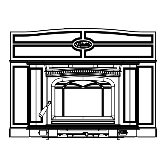
Page 5: Dimensions
Dimensions WITH REGULAR SURROUND WITH OVERSIZED SURROUND ALT5.INSA 070910-24... -
Page 6: Installation
Installation Full Flue Liner Fig. # 2 (Required in Canada) Your Insert is designed to be installed into a masonry or factory-built, zero-clearance wood burning fi replace. The masonry fi replace must be built according to the requirements of the Standard of Chimneys, Fireplaces, Vents and Solid Fuel Burning appliances, N.F.P.A. -
Page 7: Full Flue Liner (Required In Canada) Fig #2
Full Flue Liner (Required in Canada) Fig #2 Into a Factory Built Fireplace Your Pacifi c Insert may be installed into a factory built fi replace This fi replace insert must be installed with a continuous liner with the following requirements: of 6”... -
Page 8: Combustion Air
Combustion Air Fig. # 6 Consult local building codes regarding combustion air supply. Intake or combustion air can be supplied to the Insert in one of two ways: 1) Outside air (O/A) supply: Remove cover from ash clean out in existing fi replace. Place a rodent screen in place of the cover. -
Page 9: Surround Assembly And Installation
Surround Assembly and Installation Fig. # 10 1) Remove crate and all plastic packaging. 2) Remove Top(A) and Shields(B). (Fig. #8) 3) Remove Surround Top from Packaging. 4) Remove Surround sides (C) from fi rebox casing by removing 2 screws (D) on each side of fi replace. (Fig #9) 5) Using a 7/16”... -
Page 10: Fan Removal/Installation
Fig. # 13 Fig. # 16 SLOT Fan Removal/Installation 8) Attach surround to fi rebox by aligning with bracket studs (L) 1) Remove Decorative Top and both Fan shields as specifi ed in then fasten with washers and nuts (M) on each side. “Fan Speed Control Relocation”... -
Page 11: Fan Speed Controller Relocation
Fan Speed Controller Relocation 4) Loosen the two bolts that secure the ash lip to the fi rebox (Fig #23), carefully lift up the ash lip and remove from the fi rebox. The fan speed controller is factory installed under the ash lip on the right hand side. - Page 12 7) Remove the control assembly from the ashlip bracket on the 9) Reconnect the wires to the fans (Fig.29) and re-attach thermal right hand side. Flip it over and reattach on the left hand side snap switch (Fig.30). Refi t ash lip, sides and top. Ensure that of the ashlip (Fig #26).
-
Page 13: Operation
Operation 1) Adjust air control to "H" (high) position (pushed to the far left) and open door. 2) Place crumpled newspaper in the centre of the heater and criss-cross with several pieces of dry kindling. Add a few Wood Selection small pieces of dry wood on top. -
Page 14: Restarting After Extended Or Overnight Burns
1) Open door and rake hot embers towards the front of the heater. Add a couple of dry, split logs on top of embers, close door. The Alderlea Insert comes equipped with twin variable speed 2) Adjust air control to “H” (high) position (pushed to the far left) circulating air blowers. -
Page 15: Creosote
Creosote In Case of a Chimney Fire 1. Prepare to evacuate to ensure everyone’s safety. Have a well understood plan of action for evacuation. Have a place Formation and Need for Removal outside where everyone is to meet. When wood is burned slowly, it produces tar and other organic 2. -
Page 16: Maintenance
Maintenance - Do not clean glass when hot - Do not use abrasive cleaners on glass 1. Burn wood only, dry and well seasoned. The denser or heavier 6. The area where boost combustion air enters the fi rebox must the wood when dry, the greater its heat value. -
Page 17: Replacement Parts
Replacement Parts (WHEN ORDERING, INCLUDE PART NUMBER WITH DESCRIPTION) ITEM DESCRIPTION PART NO. 1....Regular Surround Top ...... ALT5.SURRA ....Oversized Surround Top ....ALT5.SURROSA 2....Fan Shield, Left ........5037.47221 3....Cast Decorative Top .......5037.4725 4....Casing Top .......... SPND.4545 5....Fan Shield, Right ........5037.47222 6....Ash Lip Assembly ......ALT5.50374723 7....Door Catch ............ -
Page 18: Understanding & Operating Your Pacifi C Energy Stove
Appendix A Understanding & Operating Your Pacifi c Energy Stove The Pacifi c Energy line of woodstoves is a culmination should be avoided until the charcoal base has become of years of research and development. Designed to be quite small. efficient, clean-burning and user-friendly, this heater will OPERATING TIPS give you years of warm service. -
Page 19: Troubleshooting
Troubleshooting Problem Cause Cure Excessive Creosote 1) Wood is too wet - Use dry wood Buildup 2) Turning down air control - Do not turn down until: too soon a) there is a good bed of coals b) the wood is charred 3) Draft too low - Improper chimney height and/or diameter - Chimney plugged or restricted, check fl ue... -
Page 20: Firebrick Installation
Firebrick Installation Alderlea T5 Insert This package contains 18 full-size fi rebricks, as well as 1 cut-size brick. With the heater in the upright position, install fi rebricks as follows: - Place fi rebricks on the bottom of the heater fi rst. Total of 7 full-size and 1cut brick. - Page 21 NOTES: ALT5.INSA 070910-24...
- Page 22 NOTES: ALT5.INSA 070910-24...
-
Page 23: Label
Label LISTED SOLID WOOD FUEL FIREPLACE INSERT / APPAREIL DU TYPE INSERTION DE COMBUSTIBLE SOLIDE DE CHEMINÉE CERTIFIED FOR USE IN CANADA AND U.S.A./CERTIFIE AU CANADA ET AUX ETATS-UNIS TESTED TO / ÉPROUVÉ SELON: ULCS628-93 / UL1482 (2010) MODEL / MODÈLE: ALT5INS SERIES / SÉRIE: D INSTALL AND USE ONLY IN ACCORDANCE WITH PACIFIC ENERGY’S INSTALLATION AND OPERATING INSTRUCTIONS. - Page 24 PACIFIC ENERGY FIREPLACE PRODUCTS LTD. www.pacifi cenergy.net Technical Support: 1-250-748-1184 2975 Allenby Rd., Duncan, B.C. V9L 6V8 Printed in Canada ALT5.INSA 070910-24...
Need help?
Do you have a question about the T5 and is the answer not in the manual?
Questions and answers