Table of Contents
Advertisement
Quick Links
SERVICE MANUAL
4
2006
YA391
AV-14A16, AV-14A16
AV-14A16
1
PRECAUTION. . . . . . . . . . . . . . . . . . . . . . . . . . . . . . . . . . . . . . . . . . . . . . . . . . . . . . . . . . . . . . . . . . . . . . . . . 1-3
2
SPECIFIC SERVICE INSTRUCTIONS . . . . . . . . . . . . . . . . . . . . . . . . . . . . . . . . . . . . . . . . . . . . . . . . . . . . . . 1-4
3
DISASSEMBLY . . . . . . . . . . . . . . . . . . . . . . . . . . . . . . . . . . . . . . . . . . . . . . . . . . . . . . . . . . . . . . . . . . . . . . . 1-5
4
ADJUSTMENT . . . . . . . . . . . . . . . . . . . . . . . . . . . . . . . . . . . . . . . . . . . . . . . . . . . . . . . . . . . . . . . . . . . . . . . 1-13
5
TROUBLESHOOTING . . . . . . . . . . . . . . . . . . . . . . . . . . . . . . . . . . . . . . . . . . . . . . . . . . . . . . . . . . . . . . . . . 1-26
COLOUR TELEVISION
/L
AV-14A16
AV-14A16/A
AV-14A16/L
TABLE OF CONTENTS
COPYRIGHT © 2006 Victor Company of Japan, Limited
, AV-14FMG6B
AV-14FMG6B/G
,
/A
/G
BASIC CHASSIS
CG4
No.YA391
2006/4
Advertisement
Chapters
Table of Contents
Troubleshooting

Related Manuals for JVC AV-14A16


Summary of Contents for JVC AV-14A16
-
Page 1: Table Of Contents
SERVICE MANUAL COLOUR TELEVISION YA391 2006 AV-14A16, AV-14A16 AV-14A16 , AV-14FMG6B BASIC CHASSIS AV-14A16 AV-14FMG6B/G AV-14A16/A AV-14A16/L TABLE OF CONTENTS PRECAUTION............... . . 1-3 SPECIFIC SERVICE INSTRUCTIONS . - Page 2 SPECIFICATION Contents AV-14A16 Items AV-14A16/A AV-14FMG6B/G AV-14A16/L Dimensions (W × H × D) 36.4 cm × 33.4 cm × 37.4 cm 46.2 cm × 34.1 cm × 37.5 cm Mass 9 kg 10 kg TV RF System B/G, I, D/K...
-
Page 3: Precaution
SECTION 1 PRECAUTION SAFETY PRECAUTIONS (1) The design of this product contains special hardware, (8) When service is required, observe the original lead dress. many circuits and components specially for safety Extra precaution should be given to assure correct lead purposes. -
Page 4: Specific Service Instructions
This function can reduce the picture noise. This function can set a channel you frequently view to the Return Channel and you can view that channel at any time with one-touch. MAIN DIFFERENCE LIST Item AV-14A16 AV-14A16/A AV-14A16/L AV-14FMG6B/G ← ←... -
Page 5: Disassembly
SECTION 3 DISASSEMBLY DISASSEMBLY PROCEDURE [AV-14A16, AV-14A16/A, AV-14A16/L] 3.1.1 REMOVING THE REAR COVER • Unplug the power cord. (1) Remove the 4 screws [A], 1 screw [B] and 1 screw [C] as shown in Fig.1. (2) Withdraw the REAR COVER toward you. - Page 6 For models AV-14A16, AV-14A16/L, AV-14A16/A FRONT CABINET CRT SOCKET PWB (Within MAIN PWB) SPEAKER SPEAKER HOLDER MAIN PWB POWER CORD REAR COVER Fig.1 1-6 (No.YA391)
- Page 7 DISASSEMBLY PROCEDURE [AV-14FMG6B/G] 3.2.1 REMOVING THE REAR COVER • Unplug the power cord. (1) Remove the 4 screws [A], 1 screw [B] and 1 screw [C] as shown in Fig.2. (2) Withdraw the REAR COVER toward you. CAUTION: When reinstalling the rear cover, carefully push it inward after inserting the MAIN PWB into the REAR COVER groove.
- Page 8 For models AV-14FMG6B/G FRONT CABINET SPEAKER CRT SOCKET PWB (Within MAIN PWB) MAIN PWB SPEAKER POWER CORD REAR COVER Fig.2 1-8 (No.YA391)
- Page 9 MEMORY IC REPLACEMENT • This model uses the memory IC. • This memory IC stores data for proper operation of the video and drive circuits. • When replacing, be sure to use an IC containing this (initial value) data. 3.3.1 MEMORY IC REPLACEMENT PROCEDURE 1.
- Page 10 LANGUAGE ENGLISH (4) MENU-4 Setting position Setting item BRIGHT STANDARD SOFT TINT COLOUR BRIGHT CONT. SHARP 3.3.3 SYSTEM CONSTANT SETTING Setting value Setting item AV-14A16 AV-14A16/A AV-14A16/L AV-14FMG6B/G ← ← COLOUR TRIPLE MULTI ← ← ← BILINGUAL ← ← ←...
- Page 11 (3) While pressing [MENU] button and [VOL+] button ON the FRONT CABINET simultaneously, turn the POWER ON. When the POWER is turned ON, the data is written in the micro-computer immediately. LOCATIONS OF FRONT PANEL BUTTONS AV-14A16 AV-14A16/A AV-14FMG6B/G AV-14A16/L...
- Page 12 REPLACEMENT OF CHIP COMPONENT 3.4.1 CAUTIONS (1) Avoid heating for more than 3 seconds. (2) Do not rub the electrodes and the resist parts of the pattern. (3) When removing a chip part, melt the solder adequately. (4) Do not reuse a chip part after removing it. 3.4.2 SOLDERING IRON (1) Use a high insulation soldering iron with a thin pointed end of it.
-
Page 13: Adjustment
SECTION 4 ADJUSTMENT ADJUSTMENT PREPARATION MEASURING INSTRUMENT AND FIXTURES (1) There are 2 ways of adjusting this TV : One is with the (1) DC voltmeter (or digital voltmeter) REMOTE CONTROL UNIT and the other is the (2) Oscilloscope conventional method using adjustment parts and (3) Signal generator components. -
Page 14: Main Pwb
ADJUSTMENT LOCATIONS CRT SOCKET PWB (SOLDER SIDE) TP-47G/R TP-47B TP-E CRT EARTH WIRE (BRAIDED ASS'Y) FRONT F901 IC702 IC701 MEMORY IC IC301 TU001 MAIN PWB 1Pin TP-91(B1) UPPER:FOCUS 2Pin NC LOWER:SCREEN 3Pin X-ray1 4Pin X-ray2 5Pin TP-E( ) 1-14 (No.YA391) - Page 15 BASIC OPERATION OF SERVICE MENU 4.6.1 TOOL OF SERVICE MENU OPERATION Operate the SERVICE MENU with the REMOTE CONTROL UNIT. 4.6.2 SERVICE MENU ITEMS With the SERVICE MENU, various adjustments can be made, and they are broadly classified in the following items of settings. 1.IF Adjustment of the IF circuits.
- Page 16 (1) By pressing the [6] key, you can change the ON or OFF [should be OFF]. Should be OFF: If it is ON, when you turn off the power and turn on a power again, the JVC’s logo will be shown about 15 seconds automatically, and the SETUP TOUR starts.
- Page 17 4.6.8 SERVICE MENU FLOW CHART SERVICE MENU 1. IF VCO (CW) ***.** TOO HIGH SERVICE MENU ABOVE REFERENCE 1.IF 2.V/C JUST REFERENCE 3.DEF 4.VSM PRESET BELOW REFERENCE 1. VCO 5.PRESET TOO LOW 6.SETUP TOUR OFF AFT ADJUST 2. DELAY POINT VCO ADJUST 1-6 : SELECT DISP : EXIT...
- Page 18 INITIAL SETTING VALUE OF SERVICE MENU • Adjustment of the SERVICE MENU is made on the basis of the initial setting values ; however, the new setting values which set the screen in its optimum condition may differ from the initial setting. •...
- Page 19 [5. PRESET] The items in the following table, it is no requirement for adjustment.If values had changed by the miss operation, set the initial setting values in the following table. COLOUR SYSTEM (Do not adjust) Initial setting value (Fixed value) Setting item Variable range SECAM...
- Page 20 ADJUSTMENT PROCEDURE 4.8.1 CHECK ITEM Measuring Item Test point Adjustment part Description instrument B1 VOLTAGE Signal TP-B1 : 1-pin (1) Receive a whole black signal. generator TP-E : 5-pin (2) Connect a DC voltmeter to 1-pin and 5-pin of S1 (S1 connector) connector.
- Page 21 Measuring Item Test point Adjustment part Description instrument DELAY POINT Signal [1. IF] (1) Receive a black and white signal (colour off). (AGC) generator 2. DELAY POINT (2) Select 1. IF. (AGC TAKE-OVER) (3) Select < 2. DELAY POINT >. Remote (4) Set the setting values of the setting items as shown control unit...
- Page 22 4.8.4 DEFLECTION CIRCUIT • There are 2 modes of adjustment (setting value) 50Hz mode and 60Hz mode, depending upon the kind of signals (vertical frequency 50Hz / 60Hz). • When adjusted in 50Hz mode and 60Hz mode will be automatically set. The setting (adjustment) using the REMOTE CONTROL UNIT is made on the basis of the initial setting values.The setting values which adjust the screen to the optimum condition can be different from the initial setting values.
- Page 23 4.8.5 VIDEO CIRCUIT The setting (adjustment) using the REMOTE CONTROL UNIT is made on the basis of the initial setting values. The setting values which adjust the screen to the optimum condition can be different from the initial setting values. Do not change the initial setting values of the setting items not listed in "ADJUSTMENT PROCEDURE".
- Page 24 (3) Adjust NTSC 3.58 COLOUR to bring the value of (A) in the voltage table. NTSC 4.43 COLOUR Voltage setting (A) (1) When NTSC 3.58 is set, NTSC 4.43 will be MODEL SECAM NTSC3.58 NTSC4.43 automatically set at the respective values. AV-14A16 AV-14A16/A AV-14A16/L AV-14FMG6B/G 1-24 (No.YA391)
- Page 25 (6) Adjust NTSC 3.58 TINT to bring the value of (B) in the voltage table in the left. NTSC 4.43 TINT (1) When NTSC 3.58 is set, NTSC 4.43 will be automatically set at the respective values. Voltage setting (B) MODEL NTSC3.58 NTSC4.43 AV-14A16 AV-14A16/A AV-14A16/L AV-14FMG6B/G (No.YA391)1-25...
-
Page 26: Troubleshooting
Measuring Item Test point Adjustment part Description instrument SECAM BLACK Signal [2. V/C] (1) Input a SECAM full field colour bar signal. OFFSET generator 7. SECAM BL ADJUST (2) Select 2. V/C from the SERVICE MENU. (3) Select < 7. SECAM BL ADJUST >. Remote (4) Set the initial setting value of <... - Page 27 Victor Company of Japan, Limited CRT Display Category 12, 3-chome, Moriya-cho, Kanagawa-ku, Yokohama-city, Kanagawa-prefecture, 221-8528, Japan (No.YA391) Printed in Japan...
- Page 28 1 Confirm which remote control you have ..3 INSTRUCTIONS 2 Inserting the batteries ........3 3 Connecting the aerial and external devices ... 4 Thank you for buying this JVC 4 Connecting the power cord ......6 colour television. 5 SETUP TOUR ..........6...
-
Page 29: Safety Precautions
Safety precautions WARNING • To prevent fire or shock hazard, do not expose the TV to rain or moisture. CAUTION • Operate only from the power source indicated on the rear of the TV. • Avoid damaging the power cord and mains plug. When you unplug the TV, pull it out by the mains plug. -
Page 30: Preparation
Preparation 1 Confirm which remote control you have RM-C360GY POWER SYSTEM PICTURE COLOUR SOUND MODE TV/VIDEO TIMER CHANNEL RETURN - / -- SCAN DISPLAY MUTING MENU CHANNEL VOLUME REMOTE CONTROL UNIT RM-C360GY 2 Inserting the batteries Correctly insert two batteries, observing the , and . -
Page 31: Connecting The Aerial And External Devices
Disconnect one input, or use one of the jacks as an output jack only (for monitoring or recording). ■ Connecting the aerial and VCR Connecting the aerial VHF/UHF outdoor aerial VIDEO AUDIO (VIDEO - 1) • Illustration of AV-14A16. Connecting the aerial and VCR VHF/UHF outdoor aerial VIDEO AUDIO (VIDEO - 1) To video To audio... - Page 32 VCR (for playing) VIDEO AUDIO (VIDEO - 1) VCR (for recording) To audio To video input input • Illustration of AV-14A16. Camcorder TV game To video To audio output output VIDEO AUDIO MENU CHANNEL • Illustration of AV-14A16.
-
Page 33: Connecting The Power Cord
Operate only from the power source indicated on the rear of the TV. 5 SETUP TOUR When the TV is first turned on it enters the SETUP TOUR mode, and the JVC logo is displayed. Follow the instructions on the on-screen display to perform the SETUP TOUR. -
Page 34: Basic Operation
Basic operation 1 Press the POWER button to turn your TV on. • If your TV does not turn on, press the POWER Main power button on the TV then press SYSTEM PICTURE the POWER button again. COLOUR SOUND MODE •... -
Page 35: Remote Control Buttons And Functions
Remote control buttons and functions In VIDEO mode: PICTURE MODE button AUTO SECAM You can select one of three picture adjustment settings as you like. NTSC3.58 NTSC4.43 Press this button to select a mode. AUTO: Automatic colour system selection. BRIGHT: Heightens contrast and sharpness. -
Page 36: Display Button
Remote control buttons and functions DISPLAY button CHANNEL SCAN button You can continuously display the current You can quickly view all TV channels channel number or VIDEO mode on the programmes that you can view on your screen. TV, and search for the programme you want to view. -
Page 37: Using The Tv's Menus
Using the TV’s menus This TV has a number of functions you can operate using the menus. To use all your TV’s functions fully, you need to understand how to use the menus. 2 Repeatedly press the MENU T buttons to display a desired menu. -
Page 38: On Timer
Using the TV’s menus When the time set for the ON TIMER ON TIMER function is reached: Your TV will automatically turn on and The TV automatically turns on and the tune into the channel you set after the channel set for the ON TIMER function is period of time you set. -
Page 39: Vnr
Using the TV’s menus CHILD LOCK (Video Noise Reduction) You can reduce the picture noise. You can disable the front control buttons of the TV. 1 Press MENU T to display the When this function is set to “ON”, the TV “MENU 1”... -
Page 40: Setup Tour
EXIT BY 2 Press MENU M. OPERATE BY -+ D I SPLA Y JVC logo is appear and the SETUP 2 Press MENU M to start the AUTO TOUR function will start. CH PRESET function. For details, see page 6. -
Page 41: Manual Ch Preset
Using the TV’s menus If the picture is not clear: MANUAL CH PRESET Fine-tune the TV channel. You can manually preset desired TV channels to desired channels. 1 Press MENU t to select “FINE”. 1 Press MENU T to display the MANUAL FINE “MENU 3”... -
Page 42: Skip
Using the TV’s menus SKIP Picture Adjustments You can set undesired channels to be You can adjust the picture as you like. skipped. Channels set to be skipped 1 Press MENU T to display the cannot be selected by the CHANNEL m “MENU 4”... -
Page 43: Using The Buttons On The Tv
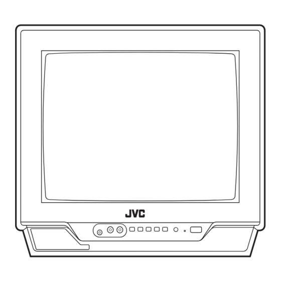
Using the buttons on the TV <AV-14A16> 1 MENU button MENU CHANNEL VOLUME POWER / ON TIMER • MENU button 2 CHANNEL m buttons EXIT • MENU m buttons 3 VOLUME m buttons • EXIT from MENU buttons 4 Remote control sensor... - Page 44 Using the buttons on the TV Basic operation Operating menus • Check to make sure the CHILD LOCK You can operate functions in menus using function is set to “OFF”. When the CHILD the front control buttons on the TV. LOCK function is set to “ON”, the TV cannot 1 Press MENU y to display a menu.
-
Page 45: Troubleshooting
Troubleshooting If there is no picture or the TV does not operate normally, make sure the problem isn’t due to the reasons indicated below. If the problem persists even after taking the measures indicated, please contact a service technician. Poor picture Cannot turn the TV on •... -
Page 46: Specifications
Specifications TV RF systems B, G, I, D, K, K1 Colour systems PAL, SECAM, NTSC 3.58 MHz/NTSC 4.43 MHz (in VIDEO mode only) Receiving channels VHF low channel (VL), VHF high channel (VH), UHF channel (U) Receives cable channels in mid band, super band and hyper band. External input / output INPUT: VIDEO input (RCA), AUDIO input (RCA) - Page 48 1 Confirm which remote control you have ..3 INSTRUCTIONS 2 Inserting the batteries ........3 3 Connecting the aerial and external devices ... 4 Thank you for buying this JVC 4 Connecting the power cord ......6 colour television. 5 SETUP TOUR ..........6...
-
Page 49: Safety Precautions
Safety precautions WARNING • To prevent fire or shock hazard, do not expose the TV to rain or moisture. CAUTION • Operate only from the power source indicated on the rear of the TV. • Avoid damaging the power cord and mains plug. When you unplug the TV, pull it out by the mains plug. -
Page 50: Preparation
Preparation 1 Confirm which remote control you have RM-C360GY POWER SYSTEM PICTURE COLOUR SOUND MODE TV/VIDEO TIMER CHANNEL RETURN - / -- SCAN DISPLAY MUTING MENU CHANNEL VOLUME REMOTE CONTROL UNIT RM-C360GY 2 Inserting the batteries Correctly insert two batteries, observing the , and . -
Page 51: Connecting The Aerial And External Devices
Preparation 3 Connecting the aerial and external devices • For further details, refer to the manuals provided with the devices you are connecting. • Connecting cables are not supplied. • The front and rear AUDIO/VIDEO input jacks are directly connected so that input to either jack is output through both. - Page 52 Preparation ■ Connecting other external devices To audio To video output output VIDEO AUDIO VCR (for playing) VCR (for recording) To audio To video input input • Illustration of AV-14FMG6B. Camcorder TV game To video To audio To video To audio output output output...
-
Page 53: Connecting The Power Cord
Operate only from the power source indicated on the rear of the TV. 5 SETUP TOUR When the TV is first turned on it enters the SETUP TOUR mode, and the JVC logo is displayed. Follow the instructions on the on-screen display to perform the SETUP TOUR. -
Page 54: Basic Operation
Basic operation 1 Press the POWER button to turn your TV on. • If your TV does not turn on, press the POWER Main power button on the TV then press SYSTEM PICTURE the POWER button again. COLOUR SOUND MODE •... -
Page 55: Remote Control Buttons And Functions
Remote control buttons and functions In VIDEO mode: PICTURE MODE button AUTO SECAM You can select one of three picture adjustment settings as you like. NTSC3.58 NTSC4.43 Press this button to select a mode. AUTO: Automatic colour system selection. BRIGHT: Heightens contrast and sharpness. -
Page 56: Display Button
Remote control buttons and functions DISPLAY button CHANNEL SCAN button You can continuously display the current You can quickly view all TV channels channel number or VIDEO mode on the programmes that you can view on your screen. TV, and search for the programme you want to view. -
Page 57: Using The Tv's Menus
Using the TV’s menus This TV has a number of functions you can operate using the menus. To use all your TV’s functions fully, you need to understand how to use the menus. 2 Repeatedly press the MENU T buttons to display a desired menu. -
Page 58: On Timer
Using the TV’s menus When the time set for the ON TIMER ON TIMER function is reached: Your TV will automatically turn on and The TV automatically turns on and the tune into the channel you set after the channel set for the ON TIMER function is period of time you set. -
Page 59: Vnr
Using the TV’s menus CHILD LOCK (Video Noise Reduction) You can reduce the picture noise. You can disable the front control buttons of the TV. 1 Press MENU T to display the When this function is set to “ON”, the TV “MENU 1”... -
Page 60: Setup Tour
EXIT BY 2 Press MENU M. OPERATE BY -+ D I SPLA Y JVC logo is appear and the SETUP 2 Press MENU M to start the AUTO TOUR function will start. CH PRESET function. For details, see page 6. -
Page 61: Manual Ch Preset
Using the TV’s menus If the picture is not clear: MANUAL CH PRESET Fine-tune the TV channel. You can manually preset desired TV channels to desired channels. 1 Press MENU t to select “FINE”. 1 Press MENU T to display the MANUAL FINE “MENU 3”... -
Page 62: Skip
Using the TV’s menus SKIP Picture Adjustments You can set undesired channels to be You can adjust the picture as you like. skipped. Channels set to be skipped 1 Press MENU T to display the cannot be selected by the CHANNEL m “MENU 4”... -
Page 63: Using The Buttons On The Tv
Using the buttons on the TV The following illustrations are of only some models are shown for explanation purpose only. Your TV may not be exactly the same as illustrated. <AV-14AG16> 1 MENU button MENU CHANNEL VOLUME POWER / • MENU button ON TIMER 2 CHANNEL m buttons... - Page 64 Using the buttons on the TV Basic operation Operating menus • Check to make sure the CHILD LOCK You can operate functions in menus using function is set to “OFF”. When the CHILD the front control buttons on the TV. LOCK function is set to “ON”, the TV cannot 1 Press MENU y to display a menu.
-
Page 65: Troubleshooting
Troubleshooting If there is no picture or the TV does not operate normally, make sure the problem isn’t due to the reasons indicated below. If the problem persists even after taking the measures indicated, please contact a service technician. Poor picture Cannot turn the TV on •... -
Page 66: Specifications
Specifications TV RF systems B, G, I, D, K, K1, M Colour systems PAL, SECAM, NTSC 3.58 MHz/NTSC 4.43 MHz Receiving channels VHF low channel (VL), VHF high channel (VH), UHF channel (U) Receives cable channels in mid band, super band and hyper band. External input / output INPUT: VIDEO input (RCA), AUDIO input (RCA) - Page 68 SCHEMATIC DIAGRAMS COLOUR TELEVISION YA391 2006 AV-14A16, AV-14A16 AV-14A16 , AV-14FMG6B CD-ROM No.SML200604 BASIC CHASSIS AV-14A16 AV-14FMG6B/G AV-14A16/A AV-14A16/L No.YA391 COPYRIGHT © 2006 Victor Company of Japan, Limited 2006/4...
-
Page 69: Standard Circuit Diagram
AV-14A16, AV-14A16 , AV-14A16 , AV-14FMG6B STANDARD CIRCUIT DIAGRAM NOTE ON USING CIRCUIT DIAGRAMS 1.SAFETY Type No indication : Ceramic capacitor The components identified by the symbol and shading are : Metalized mylar capacitor critical for safety. For continued safety replace safety ciritical : Polypropylene capacitor components only with manufactures recommended parts. - Page 70 SEMICONDUCTOR SHAPES ..............2-2 BLOCK DIAGRAM ..................2-3 CIRCUIT DIAGRAMS ..................2-5 MAIN PWB CIRCUIT DIAGRAM [AV-14A16, AV-14A16/A, AV-14A16/L] (1/3) ..........2-5 MAIN PWB CIRCUIT DIAGRAM [AV-14A16, AV-14A16/A, AV-14A16/L] (2/3)(3/3) ........2-7 MAIN PWB CIRCUIT DIAGRAM [AV-14FMG6B/G] (1/3) ................2-9 MAIN PWB CIRCUIT DIAGRAM [AV-14FMG6B/G] (2/3)(3/3) ..............2-11 PATTERN DIAGRAMS ................
-
Page 71: Block Diagram
BLOCK DIAGRAM MAIN PWB(1/3, 2/3) POWER LED STB_PW IC703 5V REG.& RESET TIMER LED SF102 TU001 Q102 LED(TIM) IF AMP SAW FILTER TUNER REMOCON REMOCON RECEIVER SCL/SDA HEADPHONE IC651 SPEAKER L AUDIO AMP AUDIO OUT SCL/SDA SCL/SDA SPEAKER R IC701 IC702 MAIN PWB(3/3) MEMORY... -
Page 72: Circuit Diagrams
CIRCUIT DIAGRAMS MAIN PWB CIRCUIT DIAGRAM [AV-14A16, AV-14A16/A, AV-14A16/L] (1/3) SHEET1 D703 R773 R772 SPEAKER IC704 SPR-39MVWF S702 QSW0619-003Z S704 QSW0619-003Z S705 GP1UM281QK POWER LED(GREEN) S701 QSW0619-003Z S703 QSW0619-003Z QSW0619-003Z REMOCON RECEIVER ON TIMER LED(RED) R721 R727 R731 R730 R726 4.7k... - Page 73 MAIN PWB CIRCUIT DIAGRAM [AV-14A16, AV-14A16/A, AV-14A16/L] (2/3),(3/3) SHEET 2 MAIN PWB(1/3) SHEET 1 AC110V-AC240V 50Hz/60Hz CN0PW QGA7901C1-02 SK351 VA901 R365 QNZ0796-001 TP-47B 2WOMR L353 Y973 Y972 QUY153-050Y Q353 R362 2SC4015/N/-T R905 S901 B-OUT 1.5k QSW0750-001 QRZ0107-152Z Y961 Q961 F901...
-
Page 74: Main Pwb Circuit Diagram [Av-14Fmg6B/G] (1/3)
MAIN PWB CIRCUIT DIAGRAM[AV-14FMG6B/G] (1/3) SHEET3 SPEAKER IC704 ON TIMER LED S702 QSW0619-003Z S704 QSW0619-003Z S705 GP1UM281QK D704 LH22440-T16 (ORANGE) S701 QSW0619-003Z S703 QSW0619-003Z QSW0619-003Z REMOCON RECEIVER D705 POWER LED (RED) R721 R727 R731 R730 R726 4.7k C719 R773 4.7k PC701 R703 1/50... - Page 75 MAIN PWB CIRCUIT DIAGRAM [AV-14FMG6B/G] (2/3),(3/3) SHEET 4 MAIN PWB(1/3) SHEET 3 AC110V-AC240V 50Hz/60Hz CN0PW QGA7901F1-02 TP-47B SK351 QNZ0796-001 R365 VA901 QAF0072-621 2WOMR Y973 Y972 L353 QUY153-050Y Q353 2SC4015/N/-T S901 R362 B-OUT QSW0750-001 Y961 QRZ0107-152Z Q961 F901 QUY160-100Y R353 C356 C901 T3.15AL AC275V...
-
Page 76: Pattern Diagrams
PATTERN DIAGRAMS MAIN PWB PATTERN [AV-14A16, AV-14A16/A, AV-14A16/L] R573 Y001 C925 D921 Y002 R574 R983 D925 Q981 J002 W543 R575 R802 C842 C571 C008 FRONT R982 Q804 C926 W012 W023 R004 R807 R815 C924 R003 R929 C942 C981 R811 W436... -
Page 77: Main Pwb Pattern [Av-14Fmg6B/G]
MAIN PWB PATTERN [AV-14FMG6B/G] R573 Y001 C925 D921 Y002 R574 D925 J002 R983 R575 W543 R802 C842 C008 C571 R982 Q804 W012 C926 R815 W023 R807 R004 C924 FRONT C942 R003 C981 W436 R811 R929 R002 C812 T921 W580 D001 W579 C581 D581... - Page 78 VOLTAGE CHARTS WAVEFORMS <MAIN PWB> <CRT SOCKET PWB> -MAIN PWB- MODE MODE MODE MODE DC (V) DC (V) DC (V) DC (V) PIN NO. PIN NO. PIN NO. PIN NO. (SHEET1) IC301 Q651 Q351 IC301-10 IC301-11 IC301-12 IC301-14 IC301-36 IC301-40 IC301-42 (1µs) (1µs)
- Page 79 Victor Company of Japan, Limited CRT Display Category 12, 3-chome, Moriya-cho, Kanagawa-ku, Yokohama-city, Kanagawa-prefecture, 221-8528, Japan (No.YA391) Printed in Japan...
-
Page 80: Parts List
PARTS LIST CAUTION The parts identified by the symbol are important for the safety . Whenever replacing these parts, be sure to use specified ones to secure the safety. The parts not indicated in this Parts List and those which are filled with lines --- in the Parts No. columns will not be supplied. P.W. - Page 81 CONTENTS USING P.W. BOARD & REMOTE CONTROL UNIT ....................3-3 EXPLODED VIEW PARTS LIST -1 [AV-14A16, AV-14A16/A ,AV-14A16/L] ............. 3-3 EXPLODED VIEW -1 [AV-14A16, AV-14A16/A ,AV-14A16/L] ................... 3-4 EXPLODED VIEW PARTS LIST -2 [AV-14FMG6B/G] ....................3-5 EXPLODED VIEW -2 [AV-14FMG6B/G] ........................3-6 PRINTED WIRING BOARD PARTS LIST [AV-14A16] ....................
-
Page 82: Exploded View Parts List
MAIN P.W.B SCG-1552A-H2 SCG-1555A-H2 SCG-1553A-H2 SCG-1544A-H2 ← ← ← REMOTE CONTROL UNIT RM-C360GY-1H EXPLODED VIEW PARTS LIST -1 [AV-14A16, AV-14A16/A ,AV-14A16/L] Ref.No. Part No. Part Name Description Local V01 A34JXV70X03BN10 PICTURE TUBE Inc.DEF YOKE, PC MAGNET AV-14A16 V01... -
Page 83: Exploded View -1 [Av-14A16, Av-14A16/A ,Av-14A16/L]
EXPLODED VIEW -1 [AV-14A16, AV-14A16/A ,AV-14A16/L] CRT SOCKET PWB (Within MAIN PWB) T522 MAIN PWB RATING LABEL 3-4(No.YA391) -
Page 84: Exploded View Parts List -2 [Av-14Fmg6B/G]
A34JXV70X03BN10 PICTURE TUBE Inc.DEF YOKE, PC MAGNET L01 QQW0171-001 DEG COIL T522 QQH0168-001 FB TRANSF LC10831-050A-H FRONT CABINET CM46880-002-H JVC MARK LC30617-001C-H E.E.WINDOW LC30616-001B-H POWER KNOB CM35235-003-H SPRING LC20292-001A-H CONTROL KNOB LC30618-001B-H LED LENS QYSBSFG4016ZA TAP SCREW... -
Page 85: Exploded View -2 [Av-14Fmg6B/G]
EXPLODED VIEW -2 [AV-14FMG6B/G] CRT SOCKET PWB (Within MAIN PWB) T522 MAIN PWB RATING LABEL 3-6(No.YA391) -
Page 86: Printed Wiring Board Parts List [Av-14A16]
PRINTED WIRING BOARD PARTS LIST [AV-14A16] MAIN P.W. BOARD ASS'Y (SCG-1552A-H2) Ref No. Part No. Part Name Description Local Ref No. Part No. Part Name Description Local C004 QETN1CM-477Z E CAPACITOR 470uF 16V M C005 QFVF1HJ-104Z MF CAPACITOR 0.1uF 50V J... - Page 87 Ref No. Part No. Part Name Description Local Ref No. Part No. Part Name Description Local C658 QETN1EM-227Z E CAPACITOR 220uF 25V M R323 NRSA63J-103X MG RESISTOR 10kΩ 1/16W J C659 QETN1HM-475Z E CAPACITOR 4.7uF 50V M R324 NRSA63J-102X MG RESISTOR 1kΩ...
- Page 88 Ref No. Part No. Part Name Description Local Ref No. Part No. Part Name Description Local R716 NRSA63J-221X MG RESISTOR 220Ω 1/16W J SF102 QAX0666-002 SAW FILTER R718 NRSA63J-561X MG RESISTOR 560Ω 1/16W J SF122 QAX0325-001 SAW FILTER R719 NRSA63J-102X MG RESISTOR 1kΩ...
-
Page 89: Printed Wiring Board Parts List [Av-14A16/A]
PRINTED WIRING BOARD PARTS LIST [AV-14A16/A] MAIN P.W. BOARD ASS'Y (SCG-1555A-H2) Ref No. Part No. Part Name Description Local Ref No. Part No. Part Name Description Local C004 QETN1CM-477Z E CAPACITOR 470uF 16V M C005 QFVF1HJ-104Z MF CAPACITOR 0.1uF 50V J... - Page 90 Ref No. Part No. Part Name Description Local Ref No. Part No. Part Name Description Local C658 QETN1EM-227Z E CAPACITOR 220uF 25V M R323 NRSA63J-103X MG RESISTOR 10kΩ 1/16W J C659 QETN1HM-475Z E CAPACITOR 4.7uF 50V M R324 NRSA63J-102X MG RESISTOR 1kΩ...
- Page 91 Ref No. Part No. Part Name Description Local Ref No. Part No. Part Name Description Local R716 NRSA63J-221X MG RESISTOR 220Ω 1/16W J SF102 QAX0666-002 SAW FILTER R718 NRSA63J-561X MG RESISTOR 560Ω 1/16W J SF122 QAX0325-001 SAW FILTER R719 NRSA63J-102X MG RESISTOR 1kΩ...
-
Page 92: Printed Wiring Board Parts List [Av-14A16/L]
PRINTED WIRING BOARD PARTS LIST [AV-14A16/L] MAIN P.W. BOARD ASS'Y (SCG-1553A-H2) Ref No. Part No. Part Name Description Local Ref No. Part No. Part Name Description Local C004 QETN1CM-477Z E CAPACITOR 470uF 16V M C005 QFVF1HJ-104Z MF CAPACITOR 0.1uF 50V J... - Page 93 Ref No. Part No. Part Name Description Local Ref No. Part No. Part Name Description Local C658 QETN1EM-227Z E CAPACITOR 220uF 25V M R323 NRSA63J-103X MG RESISTOR 10kΩ 1/16W J C659 QETN1HM-475Z E CAPACITOR 4.7uF 50V M R324 NRSA63J-102X MG RESISTOR 1kΩ...
- Page 94 Ref No. Part No. Part Name Description Local Ref No. Part No. Part Name Description Local R716 NRSA63J-221X MG RESISTOR 220Ω 1/16W J SF102 QAX0666-002 SAW FILTER R718 NRSA63J-561X MG RESISTOR 560Ω 1/16W J SF122 QAX0325-001 SAW FILTER R719 NRSA63J-102X MG RESISTOR 1kΩ...
-
Page 95: Printed Wiring Board Parts List [Av-14Fmg6B/G]
PRINTED WIRING BOARD PARTS LIST [AV-14FMG6B/G] MAIN P.W. BOARD ASS'Y (SCG-1544A-H2) Ref No. Part No. Part Name Description Local Ref No. Part No. Part Name Description Local C001 QETN1HM-106Z E CAPACITOR 10uF 50V M IC301 NN5198K C002 NCB31HK-103X C CAPACITOR 0.01uF 50V K IC421 LA78040N... - Page 96 Ref No. Part No. Part Name Description Local Ref No. Part No. Part Name Description Local C571 QETN1AM-107Z E CAPACITOR 100uF 10V M R162 NRSA63J-122X MG RESISTOR 1.2kΩ 1/16W J C572 QETN1EM-476Z E CAPACITOR 47uF 25V M R163 NRSA63J-222X MG RESISTOR 2.2kΩ...
- Page 97 Ref No. Part No. Part Name Description Local Ref No. Part No. Part Name Description Local R660 NRSA63J-153X MG RESISTOR 15kΩ 1/16W J F901 QMF51E2-3R15-S FUSE 3.15A AC250V R661 QRE121J-271Y C RESISTOR 270Ω 1/2W J J002 QNN0384-001 PIN JACK VIDEO,AUDIO IN/OUT(REAR) R662 QRE121J-271Y C RESISTOR...
-
Page 98: Remote Control Unit Parts List (Rm-C360Gy-1H)
REMOTE CONTROL UNIT PARTS LIST (RM-C360GY-1H) Ref No. Part No. Part Name Description Local R25-8567 BATTERY COVER PACKING [AV-14A16, AV-14A16/A ,AV-14A16/L] PACKING PARTS LIST [AV-14A16, AV-14A16/A ,AV-14A16/L] Ref.No. Part No. Part Name Description Local GG10281-010A-H PACKING CASE LC10166-003B-H... -
Page 99: Packing [Av-14Fmg6B/G]
PACKING [AV-14FMG6B/G] PACKING PARTS LIST [AV-14FMG6B/G] Ref.No. Part No. Part Name Description Local LC12622-001A-H PACKING CASE LC10833-002B-H CUSHION ASS'Y 4pcs in 1set GG30097-002A-H POLY BAG GG30096-001A-H POLY BAG ------------ BATTERY AA/R6 1.5V(x2) GGT0109-001A-H INST BOOK English GGT0110-001A-H DIGEST MANUAL Arabic,French,Persian,Russian ...
Need help?
Do you have a question about the AV-14A16 and is the answer not in the manual?
Questions and answers
How to turn off a off timer with out remote ?
To turn off the OFF TIMER on a JVC AV-14A16 without a remote, use the TV’s front panel buttons. Press the button labeled for the OFF TIMER repeatedly until the timer is set to 0. This cancels the OFF TIMER function.
This answer is automatically generated