Advertisement
Quick Links
Metallwarenfabrik Gemmingen GmbH & Co.
D - 75050 Gemmingen
Telefon : +49 7267 8060 • Telefax : +49 7267 806100
www.metallwarenfabrik.com
Operation manual of
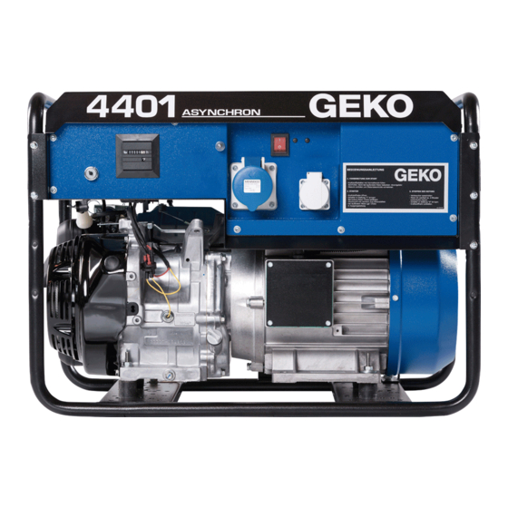
Geko
Stromerzeuger-Systeme
4401 E -AA/HHBA • 4401 E -AA/HEBA
5401 ED -AA/HHBA • 5401 ED -AA/HEBA
6401 ED -AA/HHBA • 6401 ED -AA/HEBA
7401 ED -AA/HHBA • 7401 ED -AA/HEBA
7401 E -AA/HHBA • 7401 E -AA/HEBA
4402 E -AA/HHBA • 4402 E -AA/HEBA
5402 ED -AA/HHBA • 5402 ED -AA/HEBA
6402 ED -AA/HHBA • 6402 ED -AA/HEBA
7402 ED -AA/HHBA • 7402 ED -AA/HEBA
®
Advertisement

Related Manuals for Geko 4401 E -AA/HEBA


Summary of Contents for Geko 4401 E -AA/HEBA
- Page 1 Operation manual of Geko ® Stromerzeuger-Systeme 4401 E -AA/HHBA • 4401 E -AA/HEBA 5401 ED -AA/HHBA • 5401 ED -AA/HEBA 6401 ED -AA/HHBA • 6401 ED -AA/HEBA 7401 ED -AA/HHBA • 7401 ED -AA/HEBA 7401 E -AA/HHBA • 7401 E -AA/HEBA 4402 E -AA/HHBA •...
- Page 3 Fuel level indicator Silent economic Operating hours counter fast start switch Fuel cock Filler neck of the fuel tank Choke Silencer Sockets Drain plug Starting handle Air filter Ground screw Ignition key switch Oil filler neck/Oil-level indicator...
-
Page 4: Safety Rules
1.2 Silent Economic As a rule, the plant should not deliver power continuously. On the contrary, electric power is often necessary urgently by inquiry similarly to the circuits of power-supplying enterprises. By using the Geko- Silent Economic mode, the rotation frequency of the engine decreases, and it increases sharply after the receipt of an inquiry for the supply of electric power. Thus, the consumption of fuel, emission of waste gases, noise level, and wear of the engine are essentially reduced. - Page 5 Driving engine It is a single-cylinder, four-cycle engine with air cooling and a horizontal crankshaft. Ignition is blocked when the level of oil is low. The automatic device stops the engine or prevents its start when the level of oil is low. This device is also triggered when the electric plant is placed on an inclined basis.
- Page 6 Electric part Warning! Access to electric components is allowed only to skilled specialists. Non-authorized works in the distribution box are strictly forbidden. After each maintenance or repair of the device, it is neces- sary to inspect safety according to VDE0701. In particular, it is necessary to test the resistance of the potential-equalization wire (<0.3Ω), insulation resistance (> 2 MΩ), and appropriate operation of avai- lable protective devices.
- Page 7 In closed buildings, it is necessary to provide the free supply (danger of the overheating damage of the plant) and removal (poisoning danger) of air. A building should be clean, dry, and protected from dust. It must not be used to store inflammable materials. Great attention should be paid to the removal of waste gases, because they include toxic carbon oxide. Flexible hoses for the removal of waste gases are not usually tight, and toxic carbon oxide can leak into the building.
- Page 8 Fuel cock 9. Start of the engine 1. Set the fuel cock to the „ON“ position. 2. If necessary, close the air valve. At hot start, the valve opens automatically. Warning! Do not use the valve if the engine is hot or the tempera- Choke ture of air is high.
- Page 9 3. Start of the engine 6401 ED-AA/HHBA 6402 ED-AA/HHBA 7401E-AA/HHBA * Set the ignition key to the „ON“ position 7401 ED-AA/HHBA * Slightly pull the starter handle up to the sensation of 7402 ED-AA/HHBA: resistance, and then sharply jerk. Warning! When the cord retracts back, do not release the ON/Ein handle.
- Page 10 12.1 Radio device FFS 100 for remote start and stop of the electric plant (option) The device is made in the form of a compact module Geko-SMD. Due to the small sizes of the transmitter, a user can constantly carry it with him.
- Page 11 Due to the application of the microprocessor measuring system, UBC is made in the form of a Geko compact module, and the controller UBC 400 can be mounted in most Geko electric plants. It is applied for both one- and three-phase electric plants.
- Page 12 B.12345h Generator operating time in hours The following menu item is selected by pressing key „up“ STATISTIK (Statistics) menu; here, the major parameters of the with pressed key „down“ (from 0 to 99999 h) system are stored and displayed L1N= 230V Voltage of phase L1 with respect to neutral N ( 0 - 300V AC ) ON= 11 Number of starts of the plant...
- Page 13 12.4.1.1 Purpose application An industrial electronic device BLC 100 Geko is intended only for application in electric plants. All electric plants should be certificated by their manufacturers for application in certain areas and checked on both resistance to overloads and operational reliability. The manufacturer of a device has to provide the corresponding safety measures. Before commissioning, the device should pass comprehensive tests for conformity to the technical and local requirements for it, as well as to the safety rules concerning the area of its application.
- Page 14 12.4.1.3 Possible dangers at unforeseen application and inadequate manipulation High voltage and current! Danger of death or heavy injury! When working with the device, it is necessary to exclude touches to current carrying parts. All sockets (of any kind) should be joined only when the device is turned off. Surfaces may be hot.
- Page 15 * a built-in device of recharging an accumulator (500 mA/12 V). The automatic emergency device BLC switches load to the Geko electric plant if circuit voltage disappears or strongly fluctuates. After the recovery of circuit voltage, load is again automatically switched to the circuit and the electric plant stops.
- Page 16 12.4.5 Operating modes of BLC 100 Warning! Turn on the unit, keeping both on-off switches in the „OFF“ position. After turning on, wait the end of built-in control BLC (about 10 s). After the light-emitting diode „Netzbetrieb“ The control of the voltage of a circuit with automatic start (Work from the circuit) has lighted up, a desired operating mode can be chosen by the on-off The ATS/Control mode of the circuit is turned on.
- Page 17 12.8 Additional fuel tank 50l or 100l (optional) The additional fuel tank enable extra long running times of the genset. A mechanical engine driven pump deliver the fuel from the lower tank to the careburator The standard 20l-tank remain usable thanks to a manual operable three-way-tap.
- Page 18 13. Possible faults and ways of their elimination Faults Origin Elimination The engine can not be started Not enough oil is filled or Check the oil level, if necessary the gas-electric generating set is refill the engine oil or provide situated on an inclined ground an even surface The gas-electric generating set...
- Page 19 Faults Origin Elimination Power reduction because Only partial loading possible of situating in the height Excessive environment temp. The gas-electric generating sets are designed for an environment temperature up to 40°C The aggregate turns off but can The overtemperature breaker See No.
- Page 20 14.2.2 Replacement of oil in the engine and check of the oil level Oil is replaced only on the hot engine and according to the engi- ne operation manual. * Place the electric plant on a suitable raised basis and slight- ly incline aside the sink hole.
- Page 21 14.3 Replacement of the generator Warning! These works must be carried out only in a specialized workshop. The generator is assembled in the reverse order. * Remove the starter case (four screws with six-sided heads). * Unscrew the central nut, remove the starter cup and fan. * Insert a lever lock with four dowels (special tool absent in the delivery set, order no.
Need help?
Do you have a question about the 4401 E -AA/HEBA and is the answer not in the manual?
Questions and answers