Table of Contents
Advertisement
Advertisement
Table of Contents

Related Manuals for Metapace S-61


Summary of Contents for Metapace S-61
- Page 2 Disclaimer Metapace reserves the right to make changes in specifications and other information contained in this document without prior notice, and the reader should in all cases consult seller to determine whether any such changes have been made. The information in this publication does not represent a commitment on the part of seller.
-
Page 3: Table Of Contents
Table of Contents Table of Contents Introduction ..................... 1 Components ..................... 1 Maintenance ..................... 1 Caution and Serial Number Labels ..............2 Cable Installation and Removal ................ 3 Scanner Operation Audible Indicators ..................... 4 Visual Indicators ....................5 Failure Modes ....................6 Typical Depth of Field .................. - Page 4 Standard Suffix Characters ................17 User Configurable Suffixes, All Data .............. 18 Code Formatting Standard Suffix Characters ................17 UPC/EAN Formatting ..................19 User Configurable Suffixes, All Data .............. 18 Keyboard Code Formatting Enable Keyboard Emulation ................21 UPC/EAN Formatting ..................19 Code Bytes Usage Keyboard Code Bytes 0-9 ....................
-
Page 5: Introduction
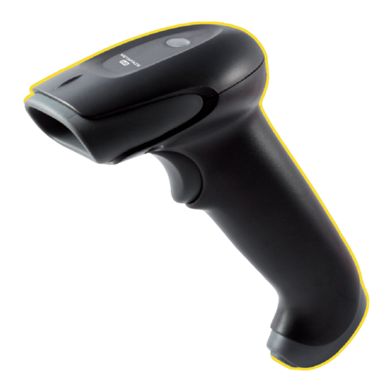
Introduction Introduction Components Item No. Description Red Output Window (Laser Aperture) Trigger Pinhole for Cable Release (see page 3) 10-Pin RJ45, Female Socket Beeper Hole LED Indicator (see page 5) Figure 1. Scanner Components Maintenance Smudges and dirt on the unit’s window can interfere with the unit’s performance. If the window requires cleaning, use only a mild glass cleaner containing no ammonia. -
Page 6: Caution And Serial Number Labels
Caution and Serial Number Labels Item Number, Serial Number and Compliance Information location. Figure 2. Label Location on the Bottom of the Scanner Caution: To maintain compliance with applicable standards, all circuits connected to the imager must meet the requirements for SELV (Safety Extra Low Voltage) according to EN/IEC 60950-1. -
Page 7: Cable Installation And Removal
Cable Installation and Removal Installation Insert the cable’s modular connector into the socket on the scanner. Pull gently on the cable strain relief to ensure the cable is installed. Figure 3. Removal Turn off power to the host system before removing the cable from the scanner. Locate the small pinhole on the front side of the scanner near the end of the handle. -
Page 8: Scanner Operation
Scanner Operation Scanner Operation Audible Indicators When the scanner is operational, the scanner provides audible feedback to indicate the status of the scanner and the last scan. Eight settings are available for the tone of the beep (normal, six alternate tones and no tone). One Beep –... -
Page 9: Visual Indicators
Visual Indicators The scanner is equipped with a red LED and green LED, which indicate the scanner’s state and the status of the current scan respectively when the unit is in operation. Figure 5. LED Location Green and Red LEDs Are Off The LEDs will not be illuminated if the scanner is not receiving power from the host or transformer. -
Page 10: Failure Modes
Failure Modes One Razzberry Tone – On Power Up This indicates the scanner has experienced a laser or flipper subsystem failure. Return the unit for repair to an Authorized Service Center. Continuous Razzberry Tone with no LEDs If, upon power up, the scanner emits a continuous razzberry tone, then the scanner has an experienced an electronic failure. -
Page 11: Troubleshooting Guide
Troubleshooting Guide Troubleshooting Guide Troubleshooting Guide The following guide is for reference purposes only. Contact a customer service representative to preserve the limited warranty terms. The following guide is for reference purposes only. Contact a customer service representative to preserve the limited warranty terms. Symptoms Possible Causes Solution... - Page 12 Symptoms Possible Causes Solution UPC/EAN, Code 39, interleaved 2 The unit powers The unit is trying to of 5, Code 93, Code 128 and up, but does not scan a particular Codabar are enabled by default. scan and/or symbology that is not Verify the type of bar code being beep.
-
Page 13: Design Specifications
Design Specifications Design Specifications Operational Visible Laser Diode (VLD) @ 650 nm Light Source: Laser Power: Less than 1.0 mW average 12.7 mm – 254 mm Depth of Scan Field: 0.33 mm (13 mil) Bar Code (0.5" – 10") Scan Speed: 72 ±... - Page 14 Electrical Electrical Input Voltage: 5VDC ± 0.25V Input Voltage: 5VDC ± 0.25V Electrical Operating Power: Standby: 700 mW Operating Power: Standby: 700 mW Decoding USB: 975 mW Input Voltage: 5VDC ± 0.25V Decoding USB: 975 mW Electrical Operating Power: Decoding KBW: Standby: 700 mW 875 mW...
-
Page 15: Configuration Introduction
Configuration Introduction Configuration Introduction Your new scanner has been factory configured with a set of default parameters. Since many host systems have unique formats and protocol requirements, a wide range of configurable features that may be selected using this bar code based configuration tool are provided. -
Page 16: Returning To Factory Defaults
Returning to Factory Defaults Scan the Recall Defaults bar code to erase all previous settings and return the scanner to its factory default communication protocol. Recall Defaults ³... -
Page 17: Code Types And Decode Rules
Code Types and Decode Rules Code Types and Decode Rules Bar code descriptions marked with an asterisk ( * ) define a feature that is a factory default. Bar codes marked with a tilde ( ~ ) require the Multi-Code configuration method. -
Page 18: Supplements
Supplements Supplements Enable Bookland (979) Supplement Required ³ * Disable Bookland (979) Supplement Required ³ Enable Bookland (978) Supplement Required ³ * Disable Bookland (978) Supplement Required ³ Enable 977 (2 Digit) Supplement Required – The scanner will require a 2 digit supplement to be ³... -
Page 19: Scanner Operation
Scanner Operation Scanner Operation Redundant Scans * 0 Redundant Scans – Requires 1 good decode for a good scan. ³ 1 Redundant Scan – Requires 2 consecutive decodes of the same bar code data for a good ³ scan. Data Transmission Delays Use these codes to select the amount of delay between sending data characters from the scanner to the host. -
Page 20: Prefixes/Suffixes
Prefixes/Suffixes Prefixes/Suffixes Scan the Enter Configuration Mode bar code before trying to set these features (see the Multi-Code Method on page 12.) User Configurable Prefixes, All Data ~ Configurable Prefix Character #1 – A prefix ID can be added and assigned for data transmission. ³... -
Page 21: User Configurable Suffixes, All Data
Enable Tab Suffix – The scanner will transmit a TAB (ASCII 09H) after each bar code. ³ * Disable Tab Suffix ³ Enable ETX Suffix – The scanner will transmit End of TeXt (ASCII 03H) after the bar code date. ³... -
Page 22: Code Formatting
Code Formatting Code Formatting UPC/EAN Formatting * Transmit UPC-A Check Digit ³ Do Not Transmit UPC-A Check Digit ³ Transmit UPC-E Check Digit ³ * Do Not Transmit UPC-E Check Digit ³ Expand UPC-E to 12 Digits – Expand UPC-E bar codes to the 12 digit equivalent, UPC-A bar codes. - Page 23 Transmit Lead Zero on UPC-E – This option will transmit a zero before each UPC-E bar code. ³ Do Not Transmit Lead Zero on UPC-E ³ Convert EAN-8 to EAN-13 – The scanner will transmit five zeros before the bar code to convert ³...
- Page 24 ASCII (HEX) ASCII Control Extended Key Null Numeric Keypad + (Plus) Num Lock Down Arrow Numeric Keypad - (Minus) Insert Delete System Request (Right Arrow) (Left Arrow) Caps Lock Shift Tab Left Alt Enter Left Control Up Arrow Home Page Up Page Down...
-
Page 25: Code Bytes 0-9
Code Bytes Usage Code Bytes Usage The scanner must be in Configuration Mode for the features requiring code bytes for configuration. The Enter/Exit Configuration Mode bar code must be scanned before starting the configuration cycle. User configurable prefix/suffix characters can then be saved by scanning the 3 digit decimal equivalent of the ASCII character into the appropriate character location with the code byte bar codes. -
Page 26: Reserved Codes
Code Byte 8 ³ Code Byte 9 ³ Reserved Codes ~ Enable Reserved Code ³ ~ Disable Reserved Code ³ Code Type Table Code Byte Code Types UPC-A UPC-E EAN-8 EAN-13 Code 39 Codabar Interleaved 2 of 5 Code 128 Code 93 MSI Plessey Code 11... -
Page 27: Ascii Reference Table
ASCII Reference Table Decimal Value/ Control HEX Value Character Code Byte Value Keyboard Eqv... - Page 28 Decimal Value/ Control HEX Value Character Code Byte Value Keyboard Eqv space,blank “ & ‘ apostrophe comma minus period number zero number one...
- Page 29 Decimal Value/ Control Keyboard HEX Value Character Code Byte Value < less than > greater than shift P letter l letter O...
- Page 30 Decimal Value/ Control Keyboard HEX Value Character Code Byte Value shift K shift L shift M à,shift N ♣, shift 0, underscore ‘ accent grave...
-
Page 31: Extended Key Code Reference Table
Decimal Value/ Control HEX Value Character Code Byte Value Keyboard Eqv vertical slash alt mode (alt mode) delete, rubout Extended Key Code Reference Table At Scan PS2 Scan Prefix/Suffix Value 3151 Code Code Hex = Decimal 80H = 128 81H = 129 ... - Page 32 At Scan PS2 Scan Prefix/Suffix Value 3151 Code Code Hex = Decimal 97H = 151 98H = 152 99H = 153 9AH = 154 9BH = 155 Numeric + 9CH = 156 Numeric - 9DH = 157 Numeric * 9EH = 158 Caps Lock 9FH = 159 Num Lock...
-
Page 33: Limited Warranty
Limited Warranty Limited Warranty Seller warrants its products to be free from defects in materials and workmanship and to conform to seller’s published specifications applicable to the products purchased at the time of shipment. This warranty does not cover any seller product which is (i) improperly installed or used;... - Page 34 All provisions of this Limited Warranty are separate and severable, which means that if any provision is held invalid and unenforceable, such determination shall not affect the validity of enforceability of the other provisions hereof. Use of any peripherals not provided by the manufacturer may result in damage not covered by this warranty.
Need help?
Do you have a question about the S-61 and is the answer not in the manual?
Questions and answers