Table of Contents
Advertisement
Advertisement
Table of Contents

Related Manuals for Metapace S-62


Summary of Contents for Metapace S-62
- Page 2 The information in this publication does not represent a commitment on the part of Metapace. Metapace shall not be liable for technical or editorial errors or omissions contained herein; nor for incidental or consequential damages resulting from the furnishing, performance, or use of this material.
-
Page 3: Table Of Contents
Table of Contents Table of Contents Table of Contents Table of Contents Chapter 1 - Getting Started Chapter 1 - Getting Started About This Manual ............1-1 Wincor Nixdorf Terminal Default Settings....2-8 Chapter 1 - Getting Started Unpacking Your Device..........1-1 Wincor Nixdorf Beetle™... - Page 4 LED Illumination - Manual Trigger....... 3-6 In-Stand Sensor Mode ..........3-6 LED Illumination - Manual Trigger....... 3-6 Presentation Mode ............3-7 In-Stand Sensor Mode ..........3-6 LED Illumination - Presentation Mode......3-7 Presentation Mode ............3-7 Presentation Sensitivity ......... 3-8 LED Illumination - Presentation Mode......
- Page 5 Other Programming Selections......5-3 Terminal ID Table ............5-4 Terminal ID Table ............5-4 Data Format Editor Commands ........5-4 Data Format Editor Commands ........5-4 Move Commands........... 5-5 Move Commands........... 5-5 Search Commands ..........5-5 Search Commands ..........5-5 Miscellaneous Commands........5-6 Miscellaneous Commands........5-6 Data Formatter.............5-7 Data Formatter.............5-7 Primary/Alternate Data Formats ........5-8...
- Page 6 Chapter 9 - Product Specifications Chapter 9 - Product Specifications Chapter 9 - Product Specifications Metapace S-62 Scanner Product Specifications ..9-1 Metapace S-62 Scanner Product Specifications ..9-1 Standard Cable Pinouts ..........9-2 Metapace S-62 Scanner Product Specifications ..9-1 Standard Cable Pinouts ..........
-
Page 7: Chapter 10 - Maintenance Repairs
EN61000-3-3. In addition, complies to 2006/95/EC Low Voltage Directive, when shipped with recommended power supply. Metapace shall not be liable for use of our product with equipment (i.e., power supplies, personal computers, etc.) that is not CE marked and does not comply with the Low Voltage Directive. - Page 8 Low Voltage Directive. Waste Electrical and Electronic Equipment Information Metapace complies with Directive 2002/96/EC OF THE EUROPEAN PARLIA- MENT AND OF THE COUNCIL of 27 January 2003 on waste electrical and electronic equipment (WEEE). This product has required the extraction and use of natural resources for its production.
-
Page 9: Solids And Water Protection
IEC 62471:2006. CB Scheme Certified to CB Scheme IEC 60950-1, Second Edition. Solids and Water Protection The Metapace S-62 has a rating of IP40, immunity of foreign particles and dripping water. Required Safety Labels Warning To reduce the possibility of heat-related injuries, avoid touching sec- tions of the scanner that feel warm. -
Page 10: Chapter 1 - Getting Started About This Manual
Metapace S-62 area-imaging scanner. Product specifications, dimensions, warranty, and customer support information are also included. Metapace bar code scanners are factory programmed for the most common termi- nal and communications settings. If you need to change these settings, pro- gramming is accomplished by scanning the bar codes in this guide. -
Page 11: Connecting With Keyboard Wedge
Unpacking Your Device Connecting the Device After you open the shipping carton containing the product, take the following steps: Connecting with USB • Check for damage during shipment. Report damage immediately to the carrier who delivered the carton. A scanner can be connected to the USB port of a computer. •... -
Page 12: Reading Techniques
Menu Bar Code Security Settings Metapace scanners are programmed by scanning menu bar codes or by sending serial commands to the scanner. If you want to restrict the ability to scan menu codes, you can use the Menu Bar Code Security settings. Please contact the... -
Page 13: Setting Custom Defaults
Setting Custom Defaults You have the ability to create a set of menu commands as your own, custom defaults. To do so, scan the Set Custom Defaults bar code below before scannning the menu commands for your custom defaults. If a menu command requires scanning numeric codes from the back cover, then a Save code, that entire sequence will be saved to your custom defaults. -
Page 14: Resetting The Factory Defaults
Resetting the Factory Defaults This selection erases all your settings and resets the scanner to the original factory defaults. It also disables all plugins . If you aren’t sure what programming options are in your scanner, or you’ve changed some options and want to restore the scanner to factory default set- tings, first scan the Remove Custom Defaults bar code, then scan Activate Defaults. -
Page 15: Keyboard Wedge
2 Programming the Interface Programming the Interface Introduction This chapter describes how to program your system for the desired interface. Programming the Interface - Plug and Play Plug and Play bar codes provide instant scanner set up for commonly used interfaces. -
Page 16: Usb Ibm Surepos
USB IBM SurePos Scan one of the following “Plug and Play” codes to program the scanner for an IBM SurePos (USB handheld scanner) or IBM SurePos (USB tabletop scanner) interface. Note: After scanning one of these codes, you must power cycle the cash register. -
Page 17: Usb Hid
USB HID Scan the following code to program the scanner for USB HID bar code scan- ners. USB HID Bar Code Scanner 2 - 3... -
Page 18: Keyboard Country Layout
Keyboard Country Layout Scan the appropriate country code below to program the keyboard layout for your country or language. As a general rule, the following characters are sup- ported, but need special care for countries other than the United States: @ | $ # { } [ ] = / ‘... - Page 19 Keyboard Country (continued) Brazil (MS) Bulgaria (Cyrillic) Bulgaria (Latin) Canada (French legacy) Canada (French) Canada (Multilingual) Croatia Czech Czech (Programmers) Czech (QWERTY) Czech (QWERTZ) Denmark Dutch (Netherlands) 2 - 10 2-10...
- Page 20 Keyboard Country (continued) Estonia Faeroese Finland France Gaelic Germany Greek Greek (220 Latin) Greek (220) Greek (319 Latin) Greek (319) Greek (Latin) Greek (MS) 2 - 11 2-11...
- Page 21 Keyboard Country (continued) Greek (Polytonic) Hebrew Hungarian (101 key) Hungary Iceland Irish Italian (142) Italy Japan ASCII Kazakh Kyrgyz (Cyrillic) Latin America Latvia 2 - 12 2-12...
- Page 22 Keyboard Country (continued) Latvia (QWERTY) Lithuania Lithuania (IBM) Macedonia Malta Mongolian (Cyrillic) Norway Poland Polish (214) Polish (Programmers) Portugal Romania Russia 2 - 13 2-13...
- Page 23 Keyboard Country (continued) Russian (MS) Russian (Typewriter) Serbia (Cyrillic) Serbia (Latin) Slovakia Slovakia (QWERTY) Slovakia (QWERTZ) Slovenia Spain Spanish variation Sweden Switzerland (French) 2 - 14 2-14...
-
Page 24: Keyboard Style
Keyboard Country (continued) Switzerland (German) Tatar Turkey F Turkey Q Ukrainian United Kingdom United Stated (Dvorak right) United States (Dvorak left) United States (Dvorak) United States (International) Uzbek (Cyrillic) Keyboard Style This programs keyboard styles, such as Caps Lock and Shift Lock. If you have used Keyboard Conversion settings, they will override any of the following Key-... - Page 25 Regular is used when you normally have the Caps Lock key off. * Regular Caps Lock is used when you normally have the Caps Lock key on. Caps Lock Shift Lock is used when you normally have the Shift Lock key on (not common to U.S.
-
Page 26: Keyboard Conversion
Emulate External Keyboard should be scanned if you do not have an external keyboard (IBM AT or equivalent). Emulate External Keyboard Note: After scanning the Emulate External Keyboard bar code, you must power cycle your computer. Keyboard Conversion Alphabetic keyboard characters can be forced to be all upper case or all lower- case. -
Page 27: Keyboard Modifiers
Default = Off. Control Character Output On * Control Character Output Off Keyboard Modifiers This modifies special keyboard features, such as CTRL+ ASCII codes and Turbo Mode. Control + ASCII Mode On: The scanner sends key combinations for ASCII control characters for values 00-1F. Windows is the preferred mode. All key- board country codes are supported. - Page 28 Turbo Mode: The scanner sends characters to a terminal faster. If the terminal drops characters, do not use Turbo Mode. Default = Off Turbo Mode On * Turbo Mode Off Numeric Keypad Mode: Sends numeric characters as if entered from a numeric keypad.
-
Page 29: Power Up Beeper
3 Input/Output Setting Input/Output Settings Power Up Beeper The scanner can be programmed to beep when it’s powered up. Scan the Off bar code(s) if you don’t want a power up beep. Default = Power Up Beeper On - Scanner. Power Up Beeper Off - Scanner * Power Up Beeper On -... -
Page 30: Good Read And Error Indicators
Good Read and Error Indicators Beeper – Good Read The beeper may be programmed On or Off in response to a good read. Turning this option off, only turns off the beeper response to a good read indication. All error and menu beeps are still audible. Default = Beeper - Good Read On. -
Page 31: Beeper Pitch – Good Read
Beeper Pitch – Good Read The beeper pitch codes modify the pitch (frequency) of the beep the scan- ner emits on a good read. Default = Medium. Low (1600 Hz) * Medium (2400 Hz) High (4200 Hz) Beeper Pitch – Error The beeper pitch codes modify the pitch (frequency) of the sound the scan- ner emits when there is a bad read or error. -
Page 32: Led – Good Read
LED – Good Read The LED indicator can be programmed On or Off in response to a good read. Default = On. * LED - Good Read On LED - Good Read Off Number of Beeps – Good Read The number of beeps of a good read can be programmed from 1 - 9. The same number of beeps will be applied to the beeper and LED in response to a good read. -
Page 33: Good Read Delay
Good Read Delay This sets the minimum amount of time before the scanner can read another bar code. Default = 0 ms (No Delay). * No Delay Short Delay (500 ms) Medium Delay (1,000 ms) Long Delay (1,500 ms) User-Specified Good Read Delay If you want to set your own length for the good read delay, scan the bar code below, then set the delay (from 0-30,000 milliseconds) by scanning digits from the inside back cover, then scanning Save. -
Page 34: Led Illumination - Manual Trigger
LED Illumination - Manual Trigger If you wish to set the illumination LED brightness, scan one of the bar codes below. This sets the LED illumination for the scanner when the trigger is pressed. Default = High. Note: The LEDs are like a flash on a camera. The lower the ambient light in the room, the brighter the LEDs need to be so the scanner can “see”... -
Page 35: Presentation Mode
Presentation Mode Presentation Mode uses ambient light to detect bar codes. The LED dims until a bar code is presented to the scanner, then the LED brightens to read the code. If the light level in the room is not high enough, Presentation Mode may not work properly. -
Page 36: Presentation Sensitivity
Presentation Sensitivity Presentation Sensitivity is a numeric range that increases or decreases the scanner's reaction time to bar code presentation. To set the sensitivity, scan the Sensitivity bar code, then scan the degree of sensitivity (from 0- 20) from the inside back cover, and Save. 0 is the most sensitive setting, and 20 is the least sensitive. - Page 37 In the example below, the white box is the centering window. The centering window has been set to 20% left, 30% right, 8% top, and 25% bottom. Since Bar Code 1 passes through the centering window, it will be read. Bar Code 2 does not pass through the centering window, so it will not be read.
- Page 38 Scan Presentation Centering On, then scan one of the following bar codes to change the top, bottom, left, or right of the centering window. Then scan the percent you want to shift the centering window using digits on the inside back cover of this manual. Scan Save. Default Presentation Centering = 40% for Top and Left, 60% for Bottom and Right.
-
Page 39: Mobile Phone Read Mode
Mobile Phone Read Mode When this mode is selected, your scanner is optimized to read bar codes from mobile phone or other LED displays. However, the speed of scanning printed bar codes may be slightly lower when this mode is enabled. Hand Held Scanning - Mobile Phone Presentation Scanning -... -
Page 40: User-Specified Reread Delay
Use shorter delays in applications where repetitive bar code scanning is required. Reread Delay only works when in Presentation Mode (see page 3-7). Default = Medium. Short (500 ms) * Medium (750 ms) Long (1000 ms) Extra Long (2000 ms) User-Specified Reread Delay If you want to set your own length for the reread delay, scan the bar code below, then set the delay (from 0-30,000 milliseconds) by scanning digits from the... -
Page 41: Centering
Centering Use Centering to narrow the scanner’s field of view to make sure that when the scanner is hand-held, it reads only those bar codes intended by the user. For instance, if multiple codes are placed closely together, centering will insure that only the desired codes are read. -
Page 42: No Read
Scan Centering On, then scan one of the following bar codes to change the top, bottom, left, or right of the centering window. Then scan the percent you want to shift the centering window using digits on the inside back cover of this manual. -
Page 43: Prefix/Suffix Overview
4 Data Editing Prefix/Suffix Overview When a bar code is scanned, additional information is sent to the host computer along with the bar code data. This group of bar code data and additional, user-defined data is called a “message string.” The selections in this section are used to build the user-defined data into the message string. -
Page 44: To Clear One Or All Prefixes Or Suffixes
symbology to which you want to apply the prefix or suffix. For example, for Code 128, Code ID is “j” and Hex ID is “6A”. Step 3. Scan the 2 hex digits from the Programming Chart inside the back cover of this manual or scan 9, 9 for all symbologies. Step 4. -
Page 45: To Add A Carriage Return Suffix To All Symbologies
Step 1. Scan the Clear One Prefix or Clear One Suffix symbol. Step 2. Determine the 2 digit Hex value from the Symbology Chart (included in the Symbology Chart, beginning on page A-1) for the symbology from which you want to clear the prefix or suffix. Step 3. -
Page 46: Suffix Selections
Suffix Selections Add Suffix Clear One Suffix Clear All Suffixes Function Code Transmit When this selection is enabled and function codes are contained within the scanned data, the scanner transmits the function code to the terminal. Charts of these function codes are provided in Supported Interface Keys starting on page... -
Page 47: Intercharacter Delay
Intercharacter Delay An intercharacter delay of up to 5000 milliseconds (in 5ms increments) may be placed between the transmission of each character of scanned data. Scan the Intercharacter Delay bar code below, then scan the number of 5ms delays, and the Save bar code using the Programming Chart inside the back cover of this manual. -
Page 48: Interfunction Delay
Interfunction Delay An interfunction delay of up to 5000 milliseconds (in 5ms increments) may be placed between the transmission of each segment of the message string. Scan the Interfunction Delay bar code below, then scan the num- ber of 5ms delays, and the Save bar code using the Programming Chart inside the back cover of this manual. -
Page 49: Add A Data Format
5 Data Formating Data Formatting Data Format Editor Introduction You may use the Data Format Editor to change the scanner’s output. For exam- ple, you can use the Data Format Editor to insert characters at certain points in bar code data as it is scanned. The selections in the following pages are used only if you wish to alter the output. - Page 50 you are programming. (See Primary/Alternate Data Formats on page 5-8 for further information.) Step 3. Terminal Type Refer to Terminal ID Table (page 5-4) and locate the Terminal ID number for your PC. Scan three numeric bar codes on the inside back cover to program the scanner for your terminal ID (you must enter 3 digits).
-
Page 51: Other Programming Selections
Other Programming Selections Clear One Data Format This deletes one data format for one symbology. If you are clearing the primary format, scan 0 from the Programming Chart inside the back cover of this manual. If you are clearing an alternate format, scan 1, 2, or 3, depending on the format you are clearing. -
Page 52: Terminal Id Table
Terminal ID Table Terminal Terminal Model(s) PC/AT and compatibles USB SurePOS Handheld Scanner USB SurePOS Tabletop Scanner RS232 True Serial PC Keyboard Mac Keyboard Japanese Keyboard (PC) HID POS Data Format Editor Commands Send Commands Send all characters F1 Include in the output message all of the characters from the input message, starting from current cursor position, followed by an insert character. -
Page 53: Move Commands
ASCII code, and xx stands for the insert character’s hex value for its ASCII code. Refer to the ASCII Conversion Chart (Code Page 1252), beginning on page A-4 for decimal, hex and character codes. Send all but the last characters E9 Include in the output message all but the last “nn”... -
Page 54: Miscellaneous Commands
Search backward for a character F9 Search the input message backward for “xx” character from the current cursor position, leaving the cursor pointing to the “xx” character. Syntax = F9xx where xx stands for the search character’s hex value for its ASCII code. -
Page 55: Data Formatter
Stop replacing characters E5 Terminates character replacement. Syntax = E5. Compare characters FE Compare the character in the current cursor position to the character “xx.” If characters are equal, move the cursor forward one position. Syntax = FExx where xx stands for the comparison character’s hex value for its ASCII code. -
Page 56: Primary/Alternate Data Formats
Default = Data Formatter On, Not Required, Keep Prefix/Suffix. * Data Formatter On, Not Required, Keep Prefix/Suffix Data Format Required, Keep Prefix/Suffix Primary/Alternate Data Formats You can save up to four data formats, and switch between these formats. Your primary data format is saved under 0. Your other three formats are saved under 1, 2, and 3. - Page 57 6 Symbologies Symbologies This programming section contains the following menu selections. Refer to Chapter 9 for settings and defaults. • All Symbologies • Interleaved 2 of 5 • Aztec Code • Korea Post • China Post (Hong Kong 2 of 5) •...
-
Page 58: All Symbologies
All Symbologies If you want to decode all the symbologies allowable for your scanner, scan the All Symbologies On code. If on the other hand, you want to decode only a particular symbology, scan All Symbologies Off followed by the On symbol for that particular symbology. -
Page 59: Codabar
Codabar <Default All Codabar Settings> Codabar On/Off * On Codabar Start/Stop Characters Start/Stop characters identify the leading and trailing ends of the bar code. You may either transmit, or not transmit Start/Stop characters. Default = Don’t Transmit . Transmit * Don’t Transmit Codabar Check Character Codabar check characters are created using different “modulos.”... -
Page 60: Codabar Concatenation
When Check Character is set to Validate, but Don’t Transmit , the unit will only read Codabar bar codes printed with a check character, but will not transmit the check character with the scanned data. * No Check Character Validate Modulo 16, but Don’t Transmit Validate Modulo 16 and Transmit... -
Page 61: Codabar Message Length
Codabar Message Length Scan the bar codes below to change the message length. Refer to Message Length Description (page 6-2) for additional information. Mini- mum and Maximum lengths = 2-60. Minimum Default = 4, Maximum Default = 60. Minimum Message Length Maximum Message Length... -
Page 62: Code 39
Code 39 < Default All Code 39 Settings > Code 39 On/Off * On Code 39 Start/Stop Characters Start/Stop characters identify the leading and trailing ends of the bar code. You may either transmit, or not transmit Start/Stop characters. Default = Don’t Transmit. -
Page 63: Code 39 Message Length
When Check Character is set to Validate and Transmit, the scanner only reads Code 39 bar codes printed with a check character, and will transmit this character at the end of the scanned data. Default = No Check Charac- ter. * No Check Character Validate, but Don’t Transmit Validate and Transmit... -
Page 64: Full Ascii
acter(s), it buffers Code 39 bar codes until it reads a Code 39 bar code that does not have the append trigger. The data is then transmitted in the order in which the bar codes were read (FIFO). Default = Off. * Off Full ASCII If Full ASCII Code 39 decoding is enabled, certain character pairs within... -
Page 65: Code 39 Code Page
Character pairs /M and /N decode as a minus sign and period respectively. Character pairs /P through /Y decode as 0 through 9. Full ASCII On * Full ASCII Off Code 39 Code Page Code pages define the mapping of character codes to characters. If the data received does not display with the proper characters, it may be because the bar code being scanned was created using a code page that is different from the one the host program is expecting. -
Page 66: Interleaved 2 Of 5
Interleaved 2 of 5 < Default All Interleaved 2 of 5 Settings > Interleaved 2 of 5 On/Off * On Check Digit No Check Digit indicates that the scanner reads and transmits bar code data with or without a check digit. When Check Digit is set to Validate, but Don’t Transmit, the unit only reads Interleaved 2 of 5 bar codes printed with a check digit, but will not transmit the check digit with the scanned data. -
Page 67: Interleaved 2 Of 5 Message Length
Interleaved 2 of 5 Message Length Scan the bar codes below to change the message length. Refer to Message Length Description (page 6-2) for additional information. Mini- mum and Maximum lengths = 2-80. Minimum Default = 4, Maximum Default = 80. Minimum Message Length Maximum Message Length NEC 2 of 5... - Page 68 When Check Digit is set to Validate and Transmit, the scanner only reads NEC 2 of 5 bar codes printed with a check digit, and will transmit this digit at the end of the scanned data. Default = No Check Digit. * No Check Digit Validate, but Don’t Transmit Validate and Transmit...
-
Page 69: Code 93
Code 93 < Default All Code 93 Settings > Code 93 On/Off * On Code 93 Message Length Scan the bar codes below to change the message length. Refer to Message Length Description (page 6-2) for additional information. Mini- mum and Maximum lengths = 0-80. Minimum Default = 0, Maximum Default = 80. -
Page 70: Code 93 Code Page
which the bar codes are read, deleting the first space from each. The scanner transmits the appended data when it reads a Code 93 bar code that starts with a character other than a space. Default = Off. * Off Code 93 Code Page Code pages define the mapping of character codes to characters. -
Page 71: Straight 2 Of 5 Industrial (Three-Bar Start/Stop)
Straight 2 of 5 Industrial (three-bar start/stop) <Default All Straight 2 of 5 Industrial Settings> Straight 2 of 5 Industrial On/Off * Off Straight 2 of 5 Industrial Message Length Scan the bar codes below to change the message length. Refer to Message Length Description (page 6-2) for additional information. -
Page 72: Straight 2 Of 5 Iata (Two-Bar Start/Stop)
Straight 2 of 5 IATA (two-bar start/stop) <Default All Straight 2 of 5 IATA Settings> Straight 2 of 5 IATA On/Off * Off Straight 2 of 5 IATA Message Length Scan the bar codes below to change the message length. Refer to Message Length Description (page 6-2) for additional information. -
Page 73: Matrix 2 Of 5
Matrix 2 of 5 <Default All Matrix 2 of 5 Settings> Matrix 2 of 5 On/Off * Off Matrix 2 of 5 Message Length Scan the bar codes below to change the message length. Refer to Message Length Description (page 6-2) for additional information. Mini- mum and Maximum lengths = 1-80. -
Page 74: Code 128
Code 128 <Default All Code 128 Settings> Code 128 On/Off * On ISBT 128 Concatenation In 1994 the International Society of Blood Transfusion (ISBT) ratified a standard for communicating critical blood information in a uniform manner. The use of ISBT formats requires a paid license. The ISBT 128 Application Specification describes 1) the critical data elements for labeling blood prod- ucts, 2) the current recommendation to use Code 128 due to its high degree of security and its space-efficient design, 3) a variation of Code 128... -
Page 75: Code 128 Message Length
Code 128 Message Length Scan the bar codes below to change the message length. Refer to Message Length Description (page 6-2) for additional information. Mini- mum and Maximum lengths = 0-80. Minimum Default = 0, Maximum Default = 80. Minimum Message Length Maximum Message Length Code 128 Append This function allows the scanner to append the data from several Code 128... - Page 76 GS1-128 <Default All GS1-128 Settings> GS1-128 On/Off * On GS1-128 Message Length Scan the bar codes below to change the message length. Refer to Message Length Description (page 6-2) for additional information. Mini- mum and Maximum lengths = 1-80. Minimum Default = 1, Maximum Default = 80.
-
Page 77: Upc-A
UPC-A Number System The numeric system digit of a U.P.C. symbol is normally transmitted at the beginning of the scanned data, but the unit can be programmed so it will not transmit it. Default = On. * On UPC-A Addenda This selection adds 2 or 5 digits to the end of all scanned UPC-A data. - Page 78 GS1 Composite Code Message Length Scan the bar codes below to change the message length. Refer to Message Length Description (page 6-2) for additional information. Mini- mum and Maximum lengths = 1-2435. Minimum Default = 1, Maximum Default = 2435. Minimum Message Length Maximum Message Length GS1 Emulation...
-
Page 79: Coupon Gs1 Databar Output
Coupon GS1 DataBar Output If you scan coupons that have both UPC and GS1 DataBar codes, you may wish to scan and output only the data from the GS1 DataBar code. Scan the GS1 Output On code below to scan and output only the GS1 DataBar code data. - Page 80 UPC-E0 Expand UPC-E Expand expands the UPC-E code to the 12 digit, UPC-A format. Default = Off. * Off UPC-E0 Addenda Required When Required is scanned, the scanner will only read UPC-E bar codes that have addenda. Default = Not Required. Required * Not Required UPC-E0 Addenda Separator...
- Page 81 UPC-E0 Check Digit Check Digit specifies whether the check digit should be transmitted at the end of the scanned data or not. Default = On. * On UPC-E0 Number System The numeric system digit of a U.P.C. symbol is normally transmitted at the beginning of the scanned data, but the unit can be programmed so it will not transmit it.
-
Page 82: Upc-E0
UPC-E1 Most U.P.C. bar codes lead with the 0 number system. For these codes, use UPC-E0 (page 6-25). If you need to read codes that lead with the 1 number system, use the UPC-E1 On selection. Default = Off. UPC-E1 On * UPC-E1 Off EAN/JAN-13 <Default All EAN/JAN Settings>... - Page 83 EAN/JAN-13 Addenda This selection adds 2 or 5 digits to the end of all scanned EAN/JAN-13 data. Default = Off for both 2 Digit and 5 Digit Addenda. 2 Digit Addenda On * 2 Digit Addenda Off 5 Digit Addenda On * 5 Digit Addenda Off EAN/JAN-13 Addenda Required When Required is scanned, the scanner will only read EAN/JAN-13 bar...
-
Page 84: Isbn Translate
EAN/JAN-13 Addenda Separator When this feature is On, there is a space between the data from the bar code and the data from the addenda. When turned Off, there is no space. Default = On. * On Note: If you want to enable or disable EAN13 with Extended Coupon Code, refer to UPC-A/EAN-13 with Extended Coupon Code (page 6-24). -
Page 85: Ean/Jan-8
EAN/JAN-8 <Default All EAN/JAN-8 Settings> EAN/JAN-8 On/Off * On EAN/JAN-8 Check Digit This selection allows you to specify whether the check digit should be transmitted at the end of the scanned data or not. Default = On. * On 6 - 31 6-31... - Page 86 EAN/JAN-8 Addenda This selection adds 2 or 5 digits to the end of all scanned EAN/JAN-8 data. Default = Off for both 2 Digit and 5 Digit Addenda. 2 Digit Addenda On * 2 Digit Addenda Off 5 Digit Addenda On * 5 Digit Addenda Off EAN/JAN-8 Addenda Required When Required is scanned, the scanner will only read EAN/JAN-8 bar...
-
Page 87: Msi
<Default All MSI Settings> MSI On/Off * Off MSI Check Character Different types of check characters are used with MSI bar codes. You can program the scanner to read MSI bar codes with Type 10 check charac- ters. Default = Validate Type 10, but Don’t Transmit. When Check Character is set to Validate Type 10/11 and Transmit, the scanner will only read MSI bar codes printed with the specified type check character(s), and will transmit the character(s) at the end of the scanned... -
Page 88: Msi Message Length
When Check Character is set to Validate Type 10/11, but Don’t Transmit, the unit will only read MSI bar codes printed with the specified type check character(s), but will not transmit the check character(s) with the scanned data. * Validate Type 10, but Don’t Transmit Validate Type 10 and Transmit Validate 2 Type 10 Characters,... -
Page 89: Gs1 Databar Omnidirectional
GS1 DataBar Omnidirectional < Default All GS1 DataBar Omnidirectional Settings > GS1 DataBar Omnidirectional On/Off * On GS1 DataBar Limited < Default All GS1 DataBar Limited Settings > GS1 DataBar Limited On/Off * On 6 - 35 6-35... -
Page 90: Gs1 Databar Expanded
GS1 DataBar Expanded < Default All GS1 DataBar Expanded Settings > GS1 DataBar Expanded On/Off * On GS1 DataBar Expanded Message Length Scan the bar codes below to change the message length. Refer to Message Length Description (page 6-2) for additional information. Mini- mum and Maximum lengths = 4-74. -
Page 91: Codablock A
Codablock A <Default All Codablock A Settings> Codablock A On/Off * Off Codablock A Message Length Scan the bar codes below to change the message length. Refer to Message Length Description (page 6-2) for additional information. Mini- mum and Maximum lengths = 1-600. Minimum Default = 1, Maximum Default = 600. -
Page 92: Codablock F
Codablock F <Default All Codablock F Settings> Codablock F On/Off * Off Codablock F Message Length Scan the bar codes below to change the message length. Refer to Message Length Description (page 6-2) for additional information. Mini- mum and Maximum lengths = 1-2048. Minimum Default = 1, Maximum Default = 2048. -
Page 93: Pdf417
PDF417 < Default All PDF417 Settings > PDF417 On/Off * On PDF417 Message Length Scan the bar codes below to change the message length. Refer to Message Length Description (page 6-2) for additional information. Mini- mum and Maximum lengths = 1-2750. Minimum Default = 1, Maximum Default = 2750. -
Page 94: Macropdf417
MacroPDF417 MacroPDF417 is an implementation of PDF417 capable of encoding very large amounts of data into multiple PDF417 bar codes. When this selection is enabled, these multiple bar codes are assembled into a single data string. Default = On. * On MicroPDF417 <... -
Page 95: Gs1 Composite Codes
MicroPDF417 Message Length Scan the bar codes below to change the message length. Refer to Message Length Description (page 6-2) for additional information. Mini- mum and Maximum lengths = 1-366. Minimum Default = 1, Maximum Default = 366. Minimum Message Length Maximum Message Length GS1 Composite Codes Linear codes are combined with a unique 2D composite component to form a... -
Page 96: Gs1 Emulation
GS1 Composite Code Message Length Scan the bar codes below to change the message length. Refer to Message Length Description (page 6-2) for additional information. Mini- mum and Maximum lengths = 1-2435. Minimum Default = 1, Maximum Default = 2435. Minimum Message Length Maximum Message Length GS1 Emulation... -
Page 97: Tcif Linked Code 39 (Tlc39)
Default = GS1 Emulation Off . GS1-128 Emulation GS1 DataBar Emulation GS1 Code Expansion Off EAN8 to EAN13 Conversion * GS1 Emulation Off TCIF Linked Code 39 (TLC39) This code is a composite code since it has a Code 39 linear component and a MicroPDF417 stacked code component. -
Page 98: Qr Code Message Length
QR Code < Default All QR Code Settings > QR Code On/Off This selection applies to both QR Code and Micro QR Code. * On QR Code Message Length Scan the bar codes below to change the message length. Refer to Message Length Description (page 6-2) for additional information. -
Page 99: Qr Code Page
information encoded in those bar codes. Once the proper number of codes is reached, the data is output in the order specified in the bar codes. Default = On. * On QR Code Page QR Code pages define the mapping of character codes to characters. If the data received does not display with the proper characters, it may be because the bar code being scanned was created using a code page that is different from the one the host program is expecting. -
Page 100: Data Matrix
Data Matrix < Default All Data Matrix Settings > Data Matrix On/Off * On Data Matrix Message Length Scan the bar codes below to change the message length. Refer to Message Length Description (page 6-2) for additional information. Mini- mum and Maximum lengths = 1-3116. Minimum Default = 1, Maximum Default = 3116. -
Page 101: Data Matrix Code Page
mined by information encoded in those bar codes. Once the proper num- ber of codes is reached, the data is output in the order specified in the bar codes. Default = On. * On Data Matrix Code Page Data Matrix Code pages define the mapping of character codes to charac- ters. -
Page 102: Aztec Code
Aztec Code < Default All Aztec Code Settings > Aztec Code On/Off * On Aztec Code Message Length Scan the bar codes below to change the message length. Refer to Message Length Description (page 6-2) for additional information. Mini- mum and Maximum lengths = 1-3832. Minimum Default = 1, Maximum Default = 3832. -
Page 103: Aztec Code Page
ter(s), it buffers the number of Aztec bar codes determined by information encoded in those bar codes. Once the proper number of codes is reached, the data is output in the order specified in the bar codes. Default = Off. * Off Aztec Code Page Aztec Code pages define the mapping of character codes to characters. -
Page 104: Chinese Sensible (Han Xin) Code
Chinese Sensible (Han Xin) Code < Default All Han Xin Settings > Han Xin Code On/Off * Off Han Xin Code Message Length Scan the bar codes below to change the message length. Refer to Message Length Description (page 6-2) for additional information. Mini- mum and Maximum lengths = 1-7833. - Page 105 China Post (Hong Kong 2 of 5) On/Off * Off China Post (Hong Kong 2 of 5) Message Length Scan the bar codes below to change the message length. Refer to Message Length Description (page 6-2) for additional information. Minimum and Maximum lengths = 2-80. Minimum Default = 4, Maxi- mum Default = 80.
-
Page 106: Korea Post
Korea Post <Default All Korea Post Settings> Korea Post * Off Korea Post Message Length Scan the bar codes below to change the message length. Refer to Message Length Description (page 6-2) for additional information. Minimum and Maximum lengths = 2-80. Minimum Default = 4, Maxi- mum Default = 48. -
Page 107: Chapter 7 - Interface Keys
7 Interface Keys Interface Keys Keyboard Function Relationships The following Keyboard Function Code, Hex/ASCII Value, and Full ASCII “CTRL”+ relationships apply to all terminals that can be used with the scanner. Refer to page 2-18 enable Control + ASCII mode. Function Code HEX/ASCII Value Full ASCII “CTRL”... - Page 108 The last five characters in the Full ASCII “CTRL”+ column ( [ \ ] 6 - ), apply to US only. The following chart indicates the equivalents of these five characters for different countries. Country Codes United States Belgium < Scandinavia <...
-
Page 109: Supported Interface Keys
Supported Interface Keys IBM PC/AT and Apple Mac/iMac Compatibles, ASCII USB PC Supported Keys Keyboard Reserved Reserved Enter (KP) Enter/Numpad Enter Cap Lock CAPS ALT make ALT make ALT break ALT break CTRL make CNTRL make CTRL break CNTRL break CR/Enter RETURN Reserved... -
Page 110: Chapter 8 - Utilities
8 Utilities Utilities To Add a Test Code I.D. Prefix to All Symbologies This selection allows you to turn on transmission of a Code I.D. before the decoded symbology. (See the Symbology Chart, beginning on page A-1) for the single character code that identifies each symbology.) This action first clears all current prefixes, then programs a Code I.D. -
Page 111: Show Data Format
Show Data Format Scan the bar code below to show current data format settings. DFMBK3?. Data Format Settings Test Menu When you scan the Test Menu On code, then scan a programming code in this manual, the scanner displays the content of a programming code. The pro- gramming function will still occur, but in addition, the content of that program- ming code is output to the terminal. -
Page 112: Chapter 9 - Product Specifications
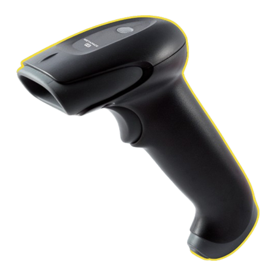
9 Product Specifications Standard Cable Pinouts Product Specifications Scanner Product Specifications Parameter Specification Mechanical Height 2.9 inches (75mm) Length 6.7 inches (170mm) Width 2.6 inches (66mm) Weight 4.2 ounces (119g) Electrical Input Voltage 4 to 5.5VDC Operating Power 2W; 400 mA (typical) @ 5V Standby Power .45W;... -
Page 113: Chapter 10 - Maintenance
10 Maintenance Maintenance Repairs Repairs and/or upgrades are not to be performed on this product. These ser- vices are to be performed only by an authorized service center (see Customer Support on page 12-1). Maintenance Your device provides reliable and efficient operation with a minimum of care. Although specific maintenance is not required, the following periodic checks ensure dependable operation: Cleaning the Device... -
Page 114: Replacing An Interface Cable
• Order replacement cables from Metapace or from an authorized distributor. • When ordering a replacement cable, specify the cable part number of the original interface cable. Replacing an Interface Cable 1. Turn the power to the host system OFF. - Page 115 • You need to program a suffix. Programming a suffix enables the scanner to output the bar code data plus the key you need (such as “CR”) to enter the data into your application. Refer to Prefix/Suffix Overview beginning on page 4-1 for further information. Does the scanner read the bar code incorrectly? If the scanner reads a bar code, but the data is not displayed correctly on the host screen:...
-
Page 116: Chapter 11 - Customer Support
(C) static electricity or electro-static dis- charge, (D) operation under conditions beyond the specified operating parame- ters, or (E) repair or service of the product by anyone other than Metapace or its authorized representatives. This warranty shall extend from the time of shipment for the duration published by Metapace for the product at the time of purchase ("Warranty Period"). - Page 117 Use of any peripherals not provided by the manufacturer may result in damage not covered by this warranty. This includes but is not limited to: cables, power supplies, cradles, and docking stations. Metapace extends these warranties only to the first end-users of the products. These warran- ties are non-transferable.
-
Page 118: Appendix A - Reference Charts
A1 Reference Charts Reference Charts Symbology Chart Possible AIM ID Code ID Symbology AIM ID Modifiers (hex) ( m ) All Symbologies (0x99) Australian Post A (0x41) Aztec Code ]z m 0-9, A-C z (0x7A) Batch Mode Quantity 5 (0x35) British Post B (0x42) Canadian Post... - Page 119 Possible AIM ID Code ID Symbology AIM ID Modifiers (hex) ( m ) EAN-8 with Add-On D (0x44) ]e m GS1 Composite y (0x79) GS1 DataBar ]e m y (0x79) ]e m GS1 DataBar Limited { (0x7B) GS1 DataBar Omnidirectional ]e m y (0x79) ]e m...
- Page 120 Possible AIM ID Code ID Symbology AIM ID Modifiers (hex) ( m ) TCIF Linked Code 39 (TLC39) T (0x54) Telepen ]B m t (0x54) UPC-A c (0x63) UPC-A with Add-On c (0x63) UPC-A with Extended c (0x63) Coupon Code UPC-E E (0x45) UPC-E with Add-On...
-
Page 121: Ascii Conversion Chart (Code Page 1252
ASCII Conversion Chart (Code Page 1252 Note: This table applies to U.S. style keyboards. Certain characters may differ depending on your Country Code/PC regional settings. Non-Printable Characters DEC HEX Character (Code) DEC HEX Character (Code) NULL DATA LINK ESCAPE (DLE) START OF HEADING DEVICE CONTROL 1 (DC1) (SOH) - Page 122 Printable Characters (Continued) DEC HEX Character DEC HEX Character DEC HEX Character < > <DEL> Extended ASCII Characters DEC HEX Character DEC HEX Character DEC HEX Character « Ö € ¬ × ‚ Ø ƒ ® Ù „ ¯ Ú …...
-
Page 123: Code Page Mapping Of Printed Bar Codes
Extended ASCII Characters (Continued) DEC HEX Character DEC HEX Character DEC HEX Character Œ · â ¸ ã Ž ¹ ä º å » æ ‘ ¼ ç ’ ½ è “ ¾ é ” ¿ ê • À ë –... - Page 124 one the host program is expecting. If this is the case, select the code page with which the bar codes were created. The data characters should then appear properly. Code Page Standard Description CP ISO646 2 (Default) ISO 2022 Automatic National Replacement Characters CP Binary ISO 8859 1 51...
-
Page 125: Unicode Key Maps
Unicode Key Maps 70 71 72 73 74 75 76 77 78 79 7A 7B 7C 7D 7E 01 02 03 04 05 06 07 08 09 0A 0B 0C 0D 4B 50 55 5A 5F 64 10 11 12 13 14 15 16 17 18 19 1A 1B 1C 1D 4C 51 56 5B 60 65 1F 20 21 22 23 24 25 26 27 28 29... -
Page 126: Sample Symbols
Sample Symbols UPC-A Interleaved 2 of 5 0 123456 7890 Code 128 1234567890 EAN-13 Code 128 Code 39 9 780330 290951 Codabar BC321 Code 93 A13579B Straight 2 of 5 Industrial 123456-9$ 123456... - Page 127 Sample Symbols Matrix 2 of 5 GS1 DataBar 6543210 PDF417 (01)00123456789012 Car Registration Postnet Zip Code Data Matrix QR Code Test Symbol Numbers 4-CB (4-State Customer Bar Code) 01,234,567094,987654321,01234567891 ID-tag (UPU 4-State) J18CUSA8E6N062315014880T...
- Page 128 Sample Symbols Aztec Micro PDF417 Package Label MaxiCode Test Message Test Message...
-
Page 129: Programming Chart
Programming Chart... - Page 130 Programming Chart Save Discard Reset Note: If you make an error while scanning the letters or digits (before scanning Save), scan Discard, scan the correct letters or digits, and Save again.
Need help?
Do you have a question about the S-62 and is the answer not in the manual?
Questions and answers