Table of Contents
Advertisement
Quick Links
Advertisement
Chapters
Table of Contents

Related Manuals for Kaysun Zen On 2014


Summary of Contents for Kaysun Zen On 2014
-
Page 1: Service Manual
Service Manual 2014 Contents... - Page 3 Contents...
-
Page 5: Part 1 General Information
Content Part 1 General Information ................1 Part 2 Indoor Units ..................5 Part 3 Outdoor Units .................. 40 Part 4 Installation ..................48 Part 5 Electrical Control System .............. 72 ※ ※ ※ ※ The specifications, designs, and information in this book are subject to change without notice for product improvement. - Page 7 General Information Part 1 General Information 1. Model Lists....................2 2. External Appearance .................. 3 2.1 Indoor Units....................... 3 2.2 Outdoor Units ......................3 4. Features ...................... 4 General Information...
-
Page 8: Model Lists
Model Lists 1. Model Lists 1.1 Indoor Units R410A Capacity multiplied by 1000Btu/h Type Function ● ● Duct Cooling and heating ● ● Super-slim 4-way cassette Cooling and heating ● ● Ceiling & Floor Cooling and heating 1.2 Outdoor Units Universal Outdoor unit Model Compressor type Compressor Brand... -
Page 9: External Appearance
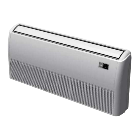
External Appearance 2. External Appearance 2.1 Indoor Units Duct Super-slim 4-way Cassette Ceiling & floor type 2.2 Outdoor Units Double fan outdoor unit General Information... -
Page 10: Features
Features 3. Features 3.1 High quality coils: The coil is constructed of advanced inner grooved copper tube and aluminum fins. 3.2 Anti-rust, 500 hours salt spray test. 3.3 Low operation sound level: Well-known stable and quiet running fan motor. 3.4 Well-known compressor. 3.5 Compact design: Smaller dimension and larger stuffing capacity. -
Page 11: Indoor Units
Indoor Units Part 2 Indoor Units Duct Type ................6 Super-slim Cassette Type ..........19 Ceiling & Floor Type ............32 Indoor Units... -
Page 12: Table Of Contents
Duct Type Duct Type 1. Features ....................... 7 2. Dimensions ....................10 3. Service Space .................... 11 3. Wiring Diagrams ..................12 5. Static Pressure ................... 13 6. Electric Characteristics ................14 7. Sound Levels ..................... 15 8. Accessories ....................16 9. -
Page 13: Features
Features 1. Features 1.1 Installation accessories: (Optional) Front Board, Canvas Air Passage, Filter, Panel, for easy installation Front Board Canvas Air Passage Filter Panel 1.2 Easy Installation: Two air inlet styles (Bottom side or Rear side) Air inlet from rear is standard for all capacity; air inlet from bottom is optional. The size of air inlet frame from rear and bottom is same, it’s very easy to move the cover from bottom to rear side, or from rear to the bottom, in order to matching the installation condition. - Page 14 Features Motor Blower Housing Ventilated Panel 1.4 Reserved remote on-off and central control ports Reserved remote on-off ports and central control ports, can connect the cable of an on-off controller or a central controller to realize remote on-off control function or group control function. Remote on-off ports Central control ports 1.5 Built-in drain pump (Optional):...
- Page 15 Features 1.6 Built-in display board The standard indoor unit can be controlled by wired controller. There is a display board with a receiver in the E-box. Move out the display, and fix it in other place, even in the distance of 10m. The unit will realized remoter control. The wired controller and the display board can display the error code or production code when the chips detect some failure.
-
Page 16: Dimensions
Dimensions 2. Dimensions Outline Air outlet o Air return Size of outline dimension dimension(mm) pening size opening size mounted plug Capacity (KBtu) 45~60 1200 1094 1240 Duct Type... -
Page 17: Service Space
Service Space 3. Service Space Ensure enough space required for installation and maintenance. There is enough space for installation and maintenance. The ceiling is horizontal, and its structure can endure the weight of the indoor unit. The outlet and the inlet are not impeded, and the influence of external air is the least. -
Page 18: Wiring Diagrams
Wiring Diagrams 4. Wiring Diagrams KPD-140 HN6、 、 、 、 KPD-176 HN6 Duct Type... -
Page 19: Static Pressure
Static Pressure 5. Static Pressure 45,000-48,000Btu/h 51,000-60,000Btu/h Super high speed Super high speed High speed High speed Mid speed Low speed Mid speed Low speed 1000 1300 1600 1900 2200 2500 2800 3100 3400 1300 1600 1900 2500 1000 2200 2800 3100 Air volume(m /h) Air volume(m /h) -
Page 20: Electric Characteristics
Electric Characteristics lectric Characteristics Indoor Unit Power Supply Model Voltage KPD-140 HN6 220-240V 198V 254V KPD-176 HN6 220-240V 198V 254V Note: MFA: Max. Fuse Amps. (A) Duct Type... -
Page 21: Sound Levels
Sound Levels 7. Sound Levels Concealed Duct Type Discharge Suction Duct Duct 1.4m Microphone Noise level dB(A) Model KPD-140 HN6 KPD-176 HN6 Duct Type... -
Page 22: Accessories
Accessories 8. Accessories Name Shape Quantity Soundproof/insulation sheath Tubing & Fittings Binding tape Seal sponge Drain joint Drainpipe Fittings Seal ring Wire controller Wire controller Owner's manual others Installation manual Duct Type... -
Page 23: The Specification Of Power
The Specification of Power 9. The Specification of Power KPD-140 HN6 Model KPD-176 HN6 Phase 1-phase Frequency and Voltage 220-240V, 50Hz INDOOR UNIT POWER POWER WIRING (mm 3×1.0 Circuit Breaker/ Fuse (A) 20/16 Phase 3-phase Frequency and Voltage 380-415V, 50Hz OUTDOOR UNIT POWER POWER WIRING (mm 5×2.5... -
Page 24: Field Wiring
Field Wiring 10. Field Wiring KPD-140 HN6、 、 、 、 KPD-176 HN6 Duct Type... -
Page 25: Super-Slim Cassette Type
Art Flux Super-slim Cassette Type Art Flux Super-slim Cassette Type 1. Features ..............20 2. Dimensions ..............24 3. Service Space ............25 3. Wiring Diagrams ............26 5. Electric Characteristics ..........27 6. Sound Levels ............. 28 7. Accessories ............... 29 8. -
Page 26: Features
Features 1. Features Overview Compact design, super slim body size, less space requiring in installation Each louver can be separately controlled, more comfort air blowing is possible. Auto-lifting panel design, more convenient to clean and maintain the filter. (optional) Old Cassette New Slim Cassette Reduction 18K-24K... - Page 27 Features New air-intake Optional ionizer generator Ionizer generator is optional to get refreshing air to your room. Ionizer can be switched on or off by remote controller. When pressing the Clean Air button on the remote controller, Ionizer will work and the indicator light on display board will shine.
- Page 28 Features External air duct design Reserve external air duct, more flexible for the air supply. Built-in draining pump Due to the improvement of structure, more convenient to repair or replace the draining pump. Draining Pump Built-in draining pump to make sure condensed water drain out reliably. Art Flux Super-slim Cassette Type...
- Page 29 Features Terminals for alarm lamp and long-distance on-off controller connection are standard Reserve terminals for the connection of alarm lamp and long-distance on-off controller, more human control. Alarm lamp Long-distance on-off controller Optional touch screen wired controller Touch screen wired controller is optional, with error code indication function. Better man-machine conversation interface.
-
Page 30: Dimensions
Dimensions 2. Dimensions Model KCIS-140 >275 KCIS-176 >317 Art Flux Super-slim Cassette Type... -
Page 31: Service Space
Service Space 3. Service Space >1000m m >1000mm Art Flux Super-slim Cassette Type... -
Page 32: Wiring Diagrams
Wiring Diagrams 4. Wiring Diagrams KCIS-140 HN6 KCIS-176 HN6 Art Flux Super-slim Cassette Type... -
Page 33: Electric Characteristics
¡Error! No hay texto con el estilo especificado en el documento. 5. Electric Characteristics Indoor Unit Power Supply Model Voltage KCIS-140 HN6 220-240V 198V 254V KCIS-176 HN6 220-240V 198V 254V Note: MFA: Max. Fuse Amps. (A) Art Flux Super-slim Cassette Type... -
Page 34: Sound Levels
Sound Levels 6. Sound Levels 1.4m Microphone Noise level dB(A) Model KCIS-140 HN6 KCIS-176 HN6 Art Flux Super-slim Cassette Type... -
Page 35: Accessories
¡Error! No hay texto con el estilo especificado en el documento. 7. Accessories Name Shape Quantity Installation paper board INSTALLATION FITTINGS Bolt M5 Tubing & Fittings Soundproof / insulation sheath Out-let pipe Out-let pipe sheath Drainpipe Fittings Out-let pipe clasp Remote controller &... -
Page 36: The Specification Of Power
The Specification of Power 8. The Specification of Power KCIS-140 HN6 Model KCIS-176 HN6 Phase 1-phase Frequency and Voltage 220-240V, 50Hz INDOOR UNIT POWER POWER WIRING (mm 3×1.0 Circuit Breaker/ Fuse (A) 20/16 Phase 3-phase Frequency and Voltage 380-415V, 50Hz OUTDOOR UNIT POWER POWER WIRING (mm 5×2.5... -
Page 37: Field Wiring
¡Error! No hay texto con el estilo especificado en el documento. 9. Field Wiring KCIS-140 HN6 KCIS-176 HN6 Art Flux Super-slim Cassette Type... -
Page 38: Ceiling & Floor Type
Ceiling & Floor Type Ceiling & Floor Type 1. Features ................33 2. Dimensions ..............34 3. Service Space ..............35 3. Wiring Diagrams ............36 5. Electric Characteristics ..........37 6. Sound Levels ..............37 7. Accessories ..............38 8. -
Page 39: Features
Features Features 1.1. New design, more modern and elegant appearance. 1.2. Convenient installation --The ceiling type can be easily installed into a corner of the ceiling even if the ceiling is very narrow --It is especially useful when installation of an air conditioner in the center of the ceiling is impossible due to a structure such as one lighting. -
Page 40: Dimensions
Dimensions Dimensions Capacity (Btu/h) KPC-140 HN6 1285 1200 KPC-176 HN6 1650 1565 Ceiling & Floor Type... -
Page 41: Service Space
Service Space Service Space Ceiling & Floor Type... -
Page 42: Wiring Diagrams
Wiring Diagrams Wiring Diagrams KPC-140 HN6 KPC-176 HN6 Ceiling & Floor Type... -
Page 43: Electric Characteristics
Electric Characteristics Electric Characteristics Indoor Units Power Supply Model Voltage Min. Max. KPC-140 HN6 220-240V 198V 254V KPC-176 HN6 220-240V 198V 254V Remark: MFA: Max. Fuse Amps. (A) Sound Levels Microphone 1.5m Air outlet side Microphone Ceiling Floor Noise level dB(A) Model KPC-140 HN6 KPC-176 HN6... -
Page 44: Accessories
Accessories Accessories 1. Remote controller Remote controller & Its 2. Remote controller holder holder 3. Mounting screw (ST2.9×10-C-H) 3. Alkaline dry batteries (AM4) 5. Owner's manual Others 6. Installation manual 7. Remote controller manual The Specification of Power KPC-140 HN6 Model KPC-176 HN6 Phase... -
Page 45: Field Wiring
Field Wiring Field Wiring KPC-140 HN6 KPC-176 HN6 Ceiling & Floor Type... -
Page 46: Part 3 Outdoor Units
Outdoor Units Part 3 Outdoor Units 1. Dimensions ....................41 2. Service Space ................... 42 3. Piping Diagrams ..................43 3. Wiring Diagrams ..................44 5. Electric Characteristics ................45 6. Operation Limits ..................46 7. Sound Levels .................... 47 Outdoor Units... -
Page 47: Dimensions
Dimensions 1. Dimensions Unit:mm Model KUE-140 HTN6 633.5 1369 KUE-176 HTN6 Outdoor Units... -
Page 48: Service Space
Service Space 2. Service Space (Wall or obstacle) Air inlet More than 30cm More than 60cm More than 30cm Maintain channel Air inlet More than 60cm Air outlet More than 200cm Outdoor Units... -
Page 49: Piping Diagrams
Piping Diagrams 3. Piping Diagrams KUE-140 HTN6、 、 、 、 KUE-176 HTN6 INDOOR OUTDOOR CHECK VALVE LIQUID SIDE (Heating Model only) 2-WAY VALVE T3 Condenser temp. sensor CAPILIARY TUBE HEAT EXCHANGE HEAT (EVAPORATOR) T4 Ambient T1 Room temp. EXCHANGE temp. sensor sensor (CONDENSER) T2 Evaporator... -
Page 50: Wiring Diagrams
Wiring Diagrams 4. Wiring Diagrams KUE-140 HTN6、 、 、 、 KUE-176 HTN6 Outdoor Units... -
Page 51: Electric Characteristics
Electric Characteristics 5. Electric Characteristics Outdoor Unit Model Voltage Min. Max. KUE-140 HTN6 380~415V 342V 435V KUE-176 HTN6 380~415V 342V 435V Outdoor Units... -
Page 52: Operation Limits
Operation Limits 6. Operation Limits Temperature Cooling operation Heating operation Mode Room temperature 17℃~32℃ 0℃~30℃ 18℃~43℃ (-7℃~43℃:For the Outdoor temperature -7℃~24℃ models with low temperature cooling system) Cooling Heating With Low Ambient Cooling System Indoor temperature( ℃ WB) Indoor temperature( ℃ WB) Outdoor Units... -
Page 53: Sound Levels
Sound Levels 7. Sound Levels Outdoor Unit Microphone 1.0m Note: H= 0.5 × height of outdoor unit Model Noise level dB(A) KUE-140 HTN6 KUE-176 HTN6 Outdoor Units... -
Page 54: Part 4 Installation
Installation Part 4 Installation 1. Installation Procedure ................49 2. Location selection ..................50 3. Indoor unit installation ................51 3. Outdoor unit installation (Side Discharge Unit) ........61 5. Refrigerant pipe installation ..............62 6. Drainage pipe installation ................ 63 7. -
Page 55: Installation Procedure
Insulation Work 1. Installation Procedure Indoor unit installation Outdoor unit installation location selection location selection Indoor unit installation Outdoor unit installation Refrigerant pipe Refrigerant pipe installation and insulation installation and insulation Drainage pipe installation Drainage pipe installation and insulation and insulation Vacuum drying and leakage checking Additional refrigerant charge Insulation the joint part of refrigerant pipe... -
Page 56: Location Selection
Location selection 2. Location selection 2.1 Indoor unit location selection The place shall easily support the indoor unit’s weight. The place can ensure the indoor unit installation and inspection. The place can ensure the indoor unit horizontally installed. The place shall allow easy water drainage. The place shall easily connect with the outdoor unit. -
Page 57: Indoor Unit Installation
Insulation Work 3. Indoor unit installation 3.1 Duct indoor unit installation 3.1.1 Service space for indoor unit 3.1.2 Bolt pitch Size of outline dimension mounted plug Capacity (KBtu) 45~60 1240 3.1.3 Install the pendant bolt Select the position of installation hooks according to the hook holes positions showed in upper picture. Drill four holes of Ø12mm, 45~50mm deep at the selected positions on the ceiling. - Page 58 Indoor unit installation 3.1.4 Install the main body Make the 4 suspender through the 4 hanger of the main body to suspend it. Adjust the hexangular nuts on the four installation hooks evenly, to ensure the balance of the body. Use a leveling instrument to make sure the levelness of the main body is within ±...
- Page 59 Insulation Work 3.1.7 Change the air inlet direction ① Take off ventilation panel and flange, cut off the staples at side rail. ① Stick the attached seal sponge as per the indicating place in the following fig, and then change the mounting positions of air return panel and air return flange .
- Page 60 Indoor unit installation 3.3 Super-slim cassette indoor unit installation 3.3.1 Service space for indoor unit Model Remark KCIS-140 Cooling / Cooling & Heating >275 R410A and R22 KCIS-176 >317 R410A and R22 Cooling / Cooling & Heating 3.3.2 Bolt pitch 3.3.3 Install the pendant bolt Select the position of installation hooks according to the hook holes positions showed in upper picture.
- Page 61 Insulation Work 3.3.4 Install the main body Make the 4 suspender through the 4 hanger of the main body to suspend it. Adjust the hexangular nuts on the four installation hooks evenly, to ensure the balance of the body. Use a leveling instrument to make sure the levelness of the main body is within ±...
- Page 62 Indoor unit installation 3.3.5 Install the panel Remove the grille Remove the 4 corner covers. Hang the panel to the hooks on the mainbody. If the panel is with auto-lift grille, please watch the ropes lifing the grille, DO NOT make the ropes enwinded or blocked. Installation...
- Page 63 Insulation Work Tighten the screws under the panel hooks till the panel closely stick on the ceiling to avoid condensate water. Hang the air-in grill to the panel, then connect the lead terminator of the swing motor and that of the control box with corresponding terminators on the body respectively.
- Page 64 Indoor unit installation 3.4 Ceiling & floor indoor unit installation 3.4.1 Service space for indoor unit 3.4.2 Bolt pitch ① Ceiling installation Capacity (Btu/h) KPC-140 HN6 1200 KPC-176 HN6 1565 ① Wall-mounted installation Installation...
- Page 65 Insulation Work 3.4.3 Install the pendant bolt ① Ceiling installation Select the position of installation hooks according to the hook holes positions showed in upper picture. Drill four holes of Ø12mm, 45~50mm deep at the selected positions on the ceiling. Then embed the expansible hooks (fittings).
- Page 66 Indoor unit installation Locate the hanging arm on the hanging screw bolt. Prepare the mounting bolts on the unit. Put the side panels and grilles back. ① Wall-mounted installation Hang the indoor unit by insert the tapping screws into the hanging arms on the main unit. (The bottom of body can touch with floor or suspended, but the body must install vertically.) Installation...
-
Page 67: Outdoor Unit Installation (Side Discharge Unit)
Insulation Work 4. Outdoor unit installation (Side Discharge Unit) 4.1 Service space for outdoor unit 4.2 Bolt pitch Model KUE-140 HTN6 633.5 KUE-176 HTN6 633.5 Installation... -
Page 68: Refrigerant Pipe Installation
Refrigerant pipe installation 4.3 Install the Unit Since the gravity center of the unit is not at its physical center, so please be careful when lifting it with a sling. Never hold the inlet of the outdoor unit to prevent it from deforming. Do not touch the fan with hands or other objects. -
Page 69: Drainage Pipe Installation
Insulation Work Flare dimension A (mm) Pipe diameter Flare shape 90 ° 4 1/4" (6.35) 3/8" (9.52) 12.0 12.4 R0.4~0.8 1/2" (12.7) 15.4 15.8 5/8" (15.9) 18.6 19.1 3/4" (19) 22.9 23.3 After flared the pipe, the opening part must be seal by end cover or adhesive tape to avoid duct or exogenous impurity come into the pipe. - Page 70 Drainage pipe installation other pipelines and ensure slope is straight. 6.2.2 Drainage pipe selection The drainage pipe diameter shall not small than the drain hose of indoor unit According to the water flow rate and drainage pipe slope to choose the suitable pipe, the water flow rate is decided by the capacity of indoor unit.
- Page 71 Insulation Work 6.2.5 The horizontal pipe layout should avoid converse flow or bad flow Drainage pipe Drainage pipe Drain tee Drainage pipe Water flow Water flow Water flow Water flow Water flow Drain tee Drain tee Water flow Water flow Water flow Water flow Branch pipe...
- Page 72 Drainage pipe installation Hanger Down incline pipe A:Length of horizontal pipe ≤ 150mm B: Lift height ≤ the pump head of water pump Flexible pipe 300mm 6.2.8 Blowhole setting For the concentrated drainage pipe system, there should design a blowhole at the highest point of main pipe to ensure the condensate water discharge smoothly.
-
Page 73: Vacuum Drying And Leakage Checking
Insulation Work 2.2 Power on and let the air conditioner operate for cooling. Check operation status of drainage pump, and then connect the plug of water level switch, check the operation sound of water pump and observe whether the water can discharge through the transparent hard pipe at drainage outlet. (In light of the length of drainage pipe, water shall be discharged about 1 minute delayed) 2.3 Stop the operation of air conditioner, power off the power supply and put the cover of water test hole... -
Page 74: Additional Refrigerant Charge
Additional refrigerant charge 1. When conduct first vacuum drying, connect pressure gauge to the infusing mouth of gas pipe and liquid pipe, and keep vacuum pump running for 1hour (vacuum degree of vacuum pump shall be reached -755mmHg). If the vacuum degree of vacuum pump could not reach -755mmHg after 1 hour of drying, it indicates that there is moisture or leakage in pipeline system and need to go on with drying for half an hour. -
Page 75: Engineering Of Insulation
Insulation Work 9. Engineering of insulation 9.1 Insulation of refrigerant pipe 9.1.1 Operational procedure of refrigerant pipe insulation Cut the suitable pipe → insulation (except joint section) → flare the pipe → piping layout and connection → vacuum drying → insulate the joint parts 9.1.2 Purpose of refrigerant pipe insulation During operation, temperature of gas pipe and liquid pipe shall be over-heating or over-cooling extremely. -
Page 76: Engineering Of Electrical Wiring
Engineering of electrical wiring 9.2.2 Purpose of drainage pipe insulation The temperature of condensate drainage water is very low. If insulation is not enough, it shall form dew and cause leakage to damage the house decoration. 9.2.3 Insulation material selection for drainage pipe The insulation material should be flame retardant material, the flame retardancy of the material should be selected according to the local law. - Page 77 Insulation Work 11.3 Test operation Set the air conditioner under the mode of "COOLING" by remote controller, and check the following points. Indoor unit Whether the switch on the remote controller works well. Whether the buttons on the remote controller works well. Whether the air flow louver moves normally.
-
Page 78: Part 5 Electrical Control System
Electrical Control Part 5 Electrical Control System 1. Electrical Control Function ..............73 2. Troubleshooting ................... 82 3. Controller ....................97 Electrical Control... - Page 79 Electrical Control Function 1. Electrical Control Function 1.1 Definition T1: Indoor room temperature T2: Coil temperature of evaporator T3: Coil temperature of condenser T4: Outdoor ambient temperature T5: Compressor discharge temperature 1.2 Main Protection 1.2.1 Time delay at restart for compressor. 1.2.2 Sensor protection at open circuit and breaking disconnection.
- Page 80 Electrical Control Function 1.3 Operation Modes and Functions 1.3.1 Fan mode 1) Outdoor fan and compressor stop. (2) Temperature setting function is disabled, and no setting temperature is displayed. (3) Indoor fan can be set to high/(med)/low/auto. (4) The louver operates same as in cooling mode. (5) Auto fan: High Medium...
- Page 81 Electrical Control Function 1.3.2.3 Indoor fan running rules In cooling mode, indoor fan runs all the time and the speed can be selected as high, medium, low and auto. The auto fan: T1-Ts High Medium 1.3.2.4 Low evaporator coil temperature T2 protection For Duct: When the evaporator coil temp.T2 keeps lower than TE5 for Time0, the compressor and outdoor fan will shut off.
- Page 82 Electrical Control Function Condition 2: TE5-2 When the evaporator coil temp.T2 keeps lower than TE5-2 for 20 minutes, the compressor and outdoor fan will shut off. When T2 is higher than TE6, the compressor and outdoor fan will restart up. Condition 3: TE5-4 When the evaporator coil temp.T2 keeps lower than TE5-4 for 8 minutes, the compressor and outdoor fan...
- Page 83 Electrical Control Function For Ceiling & Floor: TE10 TE11 When T3 ≥ TE10, the compressor will shut off. When T3 < TE11,the compressor will restart. 1.3.3 Heating Mode 1.3.3.1 Compressor running rules: For Duct & super-slim cassette type: Once the compressor starts up, it keeps running 7 minutes, For Ceiling &...
- Page 84 Electrical Control Function Auto fan action: For Duct & super-slim cassette type: For Ceiling & Floor: setting temperature-compensation.=4 ° C T1-Ts Medium High For Ceiling & Floor: setting temperature-compensation.=1 ° C T1-Ts Medium High 1.3.3.4 Defrosting mode: : : : Condition of defrosting: AC will enter defrosting mode if any of the following items is satisfied.
- Page 85 Electrical Control Function Defrosting action: : : : Setting defrosting time Compressor 4 way valve Outdoor fan Indoor fan 1.3.3.5 High evaporator coil temp.T2 protection: For Duct and Super-slim Cassette: Compressor off Outdoor fan off Compressor on Outdoor fan off TE10 Compressor on Outdoor fan on TE11...
- Page 86 Electrical Control Function For Duct and Super-slim Cassette: ∆ T=T1-Ts Running mode Cooling ∆ T > 2 ℃ Fan-only -1 ≤∆ T ≤ 2 ℃ Heating ∆ T<-1 ℃ For Ceiling & Floor: ∆ T=T1-Ts Running mode Cooling ∆ T > 2 ℃ Fan-only -1<...
- Page 87 Electrical Control Function 1.3.7.2. Turning off, changing mode or setting fan speed will cancel economy function. 1.3.7.3 Operation process in sleep mode is as follow: After pressing ECONOMIC or SLEEP button on the controller, the machine will go into economy mode. When cooling, the setting temperature rises 1 ℃...
-
Page 88: Troubleshooting
Troubleshooting 2. Troubleshooting 2.1 Display board 2.1.1 Icon explanation on indoor display board (A5 Duct& High Static Pressure Duct) PRE-DEF indicator(cooling and heating type) or fan only indicator(cooling only type) Alarm indicator Timer indicator Infrared signal receiver Operation lamp Display digital tube Temporary button OPERATION TIMER DEF./FAN ALARM MANUAL... - Page 89 Troubleshooting 2.2. Self-diagnosis Indoor unit’s LED indication (1) For Duct Running Timer Defrosting Alarm Display(digital Malfunction lamp lamp lamp lamp tube) Communication malfunction between indoor ☆ ☆ and outdoor units Open or short circuit of T1 temperature ☆ sensor Open or short circuit of T2 temperature ☆...
- Page 90 Troubleshooting For Ceiling & Floor Running Timer Defrosting Alarm Malfunction lamp lamp lamp lamp Communication malfunction between indoor and outdoor ☆ ☆ units Open or short circuit of T1 temperature sensor ☆ Open or short circuit of T2 temperature sensor ☆...
- Page 91 Troubleshooting 2.3. Solving steps for typical malfunction (1) For indoor unit a. Communication malfunction between indoor and outdoor units(E1) Electrical Control...
- Page 92 Troubleshooting b. Open or short circuit of temperature sensor( ( ( ( E2, , , , E3, E4) ) ) ) Check the connections between temperature Correct the connections. sensor and PCB. Are the connections good? Check the resistance value of the sensor via Appendix 1 Is it normal? Replace indoor or outdoor PCB.
- Page 93 Troubleshooting c. Outdoor unit malfunction(E6) Outdoor unit malfunction Whether the outdoor main board has error Refer to corresponding solving steps display Whether the outdoor Check whether the power is on unit is power on Check whether the communication wire Connect the wiring well or between the indoor and replace the communication wire outdoor unit is...
- Page 94 Troubleshooting d. Indoor EEPROM malfunction(E7) Shut off the power supply and turn it on 5 seconds later. Is it still displaying the error code? If the EEPROM chip is welded on PCB, replace the PCB directly. Otherwise, Insert the EEPROM well check whether the EEPROM chip plugged in PCB well?
- Page 95 Troubleshooting f. Indoor fan speed has been out of control(Eb) Electrical Control...
- Page 96 Troubleshooting Index 1: 1.Indoor DC fan motor(control chip is inside fan motor) Measure the resistance value of each winding by using the tester. If any resistance value is zero, the fan motor must have problems and need to be replaced. Color Black White...
- Page 97 Troubleshooting For the super-slim cassette with up-down panel a. Communication error between indoor unit and up-down panel b. Up-down panel is defective Electrical Control...
- Page 98 Troubleshooting c Up-down panel is not closed Electrical Control...
- Page 99 Troubleshooting (2) For the outdoor unit a. Phase sequence error: Phase sequence error Change the order of two of the wires to power supply. Switch on the unit again. If the problem cannot be solved, the outdoor PCB is defective b.
- Page 100 Troubleshooting c. Overload of current Overload of current Check the current, normally Is the current in rated range? Possible reason The outdoor PCB is defective Outdoor fan is defective The compressor is defective Refrigerant is over charged Air enter the refrigerant system d.
- Page 101 Troubleshooting e. High temperature protection of condenser High temperature protection of condenser Check the resistance of the temp. sensor according to Appendix 1 , is it normal? Replace the sensor Possible reason 1. Air or other gas in the refrigerant. 2.
- Page 102 Troubleshooting Appendix 1 Temperature Sensor Resistance Value Table ( ℃ --K) K Ohm K Ohm K Ohm K Ohm ℃ ℃ ℃ ℃ ℃ ℃ ℃ ℃ ℃ ℃ ℃ ℃ ℃ ℃ ℃ ℃ 12.6431 2.35774 0.62973 115.266 108.146 12.0561 2.27249 0.61148...
- Page 103 Controller 3. Controller KI-01 Wireless Remote Controller (Optional) Electrical Control...
- Page 104 Controller 3.1.1 PRECAUTIONS Curtain, door or the like objects will prevent the remote signal from being received by air conditioner. Do not get the interior of remote controller wet. It is forbidden to expose it to direct sunlight or locate it in the place with high temp.
- Page 105 Controller 3.1.3 INDICATORS AND FUNCTIONS Temp: Display the set temperature. Adjust temperature via ▲ and ▼ . No display in this area if the unit is on FAN mode. Transmitting display: The icon will flash once when the signal is sent by remote controller. ON/FF: Icon is displayed when the remote controller is turned on, or vice versa.
-
Page 106: Operation Instructions
Controller 3.1.4 OPERATION INSTRUCTIONS Install and replace batteries Install 2 pieces of 7# alkaline batteries. Slide the cover to install batteries and make sure to place them in right pole. AUTO operation Switch on the power and running indicator light on indoor unit flashes. 1. - Page 107 Controller 3.2 KC-01.2 R Wired IR Remote Controller (Optional) 3.2.1 Safety precautions Read the safety precautions carefully before installing the unit. Stated below are important safety issues that must be obeyed. WARNING Means improper handling may lead to personal severe injury. CAUTION Means improper handling may lead to personal injury or property loss.
- Page 108 Controller 3.2.2 Installation accessory Select the installation location Don’t install at the place where contents with heavy oil, vapor or sulphurous gas, otherwise, this product would be deformed that would lead to system malfunction. Preparation before installation 1. Please confirm that all the following parts you have been supply. 2.
- Page 109 Controller 1. Connect the male joint of 5-core wires group of the signal received panel with the female 5-core terminal of signal received panel. (See Fig.3-2) 5. Adjust the length of two plastic bolts base on the length of throughout from standard electric cabinet to the wall.
- Page 110 Controller 3.2.4 Wiring diagram for wiring wire controller with air conditioner 1. Wiring diagram of wire controller connects with four-way cassettes indoor unit 2. Wiring diagram of wire controller connects with ceiling and duct type indoor unit 3.2.5. Specification 3.2.6. General function Main functions of this wire controller as follows: Connect with indoor unit via the five ports of A, B, C, D, E.
- Page 111 Controller 3.2.7. Name and operation of the button on the wire controller Mode select button ON/OFF button Adjust button Adjust button Time button FAN speed button Timer button Swing button Cancel button Infrared remote receiver ① MODE Select Button: Each time you push the button, a mode is selected in a sequence that goes from AUTO、 COOL、DRY、HEAT and FAN as the following figure indicates: AUTO →...
- Page 112 Controller ⑤ Time Button: Normally, LCD displays the current time of the setting clock (however, LCD would display 12:00 when the first time power to the wire controller or reset the wire controller). Press this key lasting for 4 seconds, the clock will flashing at the frequency of 0.5 Sec. by using and to adjust the time, 1 minute to be increased/decreased for every once press the▲...
- Page 113 Controller Display the set temperature. Adjust temperature via▲ and ▼. No display in this area if the unit is on FAN mode. ③ Time ON indication: During setting the Timing ON or after set the Timing ON, the LCD would display “TIME ON”.
- Page 114 Controller 3. Push the ON/OFF button. The operation lamp lights and the air conditioner starts to operate in the DRY mode. Push the ON/OFF button again to stop this unit operation. NOTE Due to the difference of the set temperature of the unit and the actual indoor temperature, the Air Conditioner when in DRY mode will automatically operate many times without running the COOL and FAN mode.
Need help?
Do you have a question about the Zen On 2014 and is the answer not in the manual?
Questions and answers