Table of Contents
Advertisement
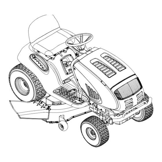
Operator's Manual
Pedal Drive Garden Tractor
Models V809H
Y809P
IMPORTANT: READ SAFETY RULES AND INSTRUCTIONS CAREFULLY
Warning:
This unit is equipped with an internal combustion engine and should not be used on or near any unimproved forest-covered,
brush-covered or grass-covered land unless the engine's exhaust system is equipped with a spark arrester meeting applicable local or
state laws (if any). If a spark arrester is used, it should be maintained in effective working order by the operator. In the State of California
the above is required by law (Section 4442 of the California Public Resources Code). Other states may have similar laws. Federal laws
apply on federal lands. A spark arrester for the muffler is available through your nearest engine authorized service dealer or contact the
service department, P.O. Box 368022 Cleveland, Ohio 44136-9722.
MTD PRODUCTS INC. P.O. BOX 368022 CLEVELAND, OHIO 44136-9722
TROY-BILT
is a registered trademark owned by Garden Way Incorporated of Troy, New York.
®
FORM NO. 770-10189C.fm
PRINTED IN U.S.A.
(3/2001)
Advertisement
Table of Contents

Related Manuals for Troy-Bilt V809H


Summary of Contents for Troy-Bilt V809H
- Page 1 Operator’s Manual Pedal Drive Garden Tractor Models V809H Y809P IMPORTANT: READ SAFETY RULES AND INSTRUCTIONS CAREFULLY Warning: This unit is equipped with an internal combustion engine and should not be used on or near any unimproved forest-covered, brush-covered or grass-covered land unless the engine’s exhaust system is equipped with a spark arrester meeting applicable local or state laws (if any).
-
Page 2: Table Of Contents
Off-Season Storage ................... 24 Attachments & Accessories ................24 Troubleshooting ....................25 Models V809H and Y809P Parts List ..............26 FINDING MODEL NUMBER This Operator’s Manual is an important part of your new lawn tractor. It will help you assemble, prepare and maintain the unit for best performance. -
Page 3: Important Safe Operation Practices
SECTION 1: IMPORTANT SAFE OPERATION PRACTICES WARNING: This symbol points out important safety instructions which, if not followed, could endanger the personal safety and/or property of yourself and others. Read and follow all instructions in this manual before attempting to operate this machine. Failure to comply with these instructions may result in personal injury. -
Page 4: Slope Operation
23. Muffler and engine become hot and can cause a 4. Follow the manufacturer’s recommendations for burn. Do not touch. wheel weights or counterweights to improve 24. Check overhead clearances carefully before driving stability. under low hanging tree branches, wires, door 5. - Page 5 e. Use extreme care when approaching blind e. Extinguish all cigarettes, cigars, pipes and corners, doorways, shrubs, trees or other other sources of ignition. objects that may block your vision of a child Never fuel machine indoors. who may run into the machine. g.
- Page 6 8. Never tamper with the safety interlock system or For safety protection, frequently check components other safety devices. Check their proper operation and replace immediately with original equipment regularly. manufacturer’s (O.E.M.) parts only, listed in this 9. After striking a foreign object, stop the engine, manual.
-
Page 7: Slope Gauge
SECTION 2: SLOPE GAUGE... -
Page 8: Tractor Set-Up
(heavy black wire) to the negative battery terminal (–) with the bolt and wing nut. • On model V809H, locate the shipping brace and • Make certain the hold-down strap is in position over accompanying warning tag found on the right side the battery, securing it in place. - Page 9 Attaching The Cutting Deck (Model Y809P) Notches Deck Lift Assembly Lift Cables Deck Lift Arms Lift Lever PTO Idler Pulley Idler Spring PTO Belt Fender Electric PTO Clutch Deck Support Pins Deck Deck Skid Rod Stabilizer Bracket Discharge Chute Front of Tractor Deck Stabilizer Rod PTO Idler Pulley Bracket NOTE:...
-
Page 10: Know Your Garden Tractor
SECTION 4: KNOW YOUR GARDEN TRACTOR NOTE: Steering Wheel not shown for clarity. Figure 4 PTO (Power Take-off) Knob Cruise Control Button Choke Control Ignition Switch Parking Brake Button Brake Pedal Shift Lever Drive Pedal Cup Holder Deck Lift Lever Systems Indicator Monitor/Hour Meter M Seat Adjustment Lever G Throttle Control Lever... -
Page 11: Throttle Control Lever
Throttle Control Lever Ignition Switch The throttle control lever is located on the right side of Never leave running WARNING: the tractor’s dash panel. This lever controls the speed machine unattended. Always disengage PTO, of the engine. When set in a given position, the throttle move shift lever into neutral position, set will maintain a uniform engine speed. -
Page 12: Shift Lever
Systems Indicator Monitor / Hour Meter Electric PTO (Power Take-off) Knob Your tractor is equipped with four indicator lights and an hour meter located on the left side of the dash panel. To engage the power to the See Figure 7. cutting deck or other (separately Battery available) attachments, pull... -
Page 13: Operating Your Garden Tractor
Deck Lift Lever Cruise Control Button Found on your tractor’s right fender, the deck lift lever is The cruise control button is used to change the height of the cutting deck. To use, located on the tractor dash panel move the lever to the left, then place in the notch best to the left of the ignition switch. -
Page 14: Driving The Tractor
Driving The Tractor WARNING: Keep hands and feet away from the discharge opening of the cutting WARNING: deck. Avoid sudden starts, ex- cessive speed and sudden stops. NOTE: The deck wheels are an anti-scalp feature of the deck and are not designed to support the weight of WARNING: Do not leave the seat of the the cutting deck. - Page 15 • Watch for holes, ruts, bumps, rocks, or other Front View Pull Out hidden objects. Uneven terrain could overturn the Push In machine. Tall grass can hide obstacles. • Avoid turns when driving on a slope. If a turn must be made, turn down the slope.
-
Page 16: Making Adjustments
• Keep the blades sharp and replace the blades To turn the tractor’s headlights off: when worn. Refer to Cutting Blades on page 23 of this • Turn the key either into the On position (to leave the manual for proper blade sharpening instructions. engine running) or the Off position (to shut the engine off). -
Page 17: Leveling The Deck
• Replace hex nut and lock washer and retighten the • The first measurement taken should be between jam nut after proper adjustment is achieved. 1/4" and 3/8" less than the second measurement. Determine the approximate distance necessary for NOTE: Threading the ball joints too far onto the drag proper adjustment and proceed, if necessary, to the links will cause the front tires to "toe-in"... -
Page 18: Maintaining Your Garden Tractor
Deck Roller Height Adjustment (Units with 50-inch Decks) Deck Roller Bracket To adjust the height of the rollers on the rear of the mowing deck, proceed as follows: • Place the deck lift lever in the bottom notch (lowest position). •... -
Page 19: Service
Air Cleaner pulleys, bearings or the engine. The use of water will result in a shortened life of the tractor and reduce its Service the pre-cleaner, if so equipped, and cartridge/ serviceability. air cleaner element as instructed in the Briggs & Stratton Operator/Owner Manual (or Kohler engine’s Lubrication Owner’s Manual) packed with your unit. -
Page 20: Changing The Deck Belt(S)
Changing the Deck Belt(s) • After cleaning the battery and terminals, apply a light coat of petroleum jelly or grease to both terminals WARNING: Be sure to shut the engine off, • Always keep the rubber boot positioned over the remove ignition key, disconnect the spark positive terminal to prevent shorting. - Page 21 Drive belt (Lower) Variable-Speed Shift Lever Pulley Drive belt (Upper) Rear Idler Pulley Battery Tray Opening Front Idler Pulley Belt Keeper Keeper Pins Engine Pulley Electric PTO Clutch Double Idler Bracket Transmission Idler Pulley Belt Keeper Idler Bracket Two-speed Transmission Pulley Transmission Front of Tractor NOTE:...
- Page 22 • Reroute the new upper drive belt as shown in Figure 16. Idler Adj. Rod Place Wrenches Here Lower Drive Belt NOTE: Proper removal of the lower drive belt requires Neutral the removal of several tractor components. Read Return through the following procedure prior to attempting it to Bracket determine if you feel you could successfully complete it.
-
Page 23: Cutting Blades
Cutting Blades Blade Separation Be sure to shut the engine off, WARNING: remove ignition key, disconnect the spark plug wire(s) and ground against the engine to prevent unintended starting before removing the cutting blade(s) for sharpening or replacement. Protect your hands by using Worn Blade Edge heavy gloves or a rag to grasp the cutting Wind Wing... -
Page 24: Off-Season Storage
SECTION 10: ATTACHMENTS & ACCESSORIES The following attachments and accessories are compatible for Garden Tractor Models V809H & Y809P. See the retailer from which you purchased your tractor, an authorized MTD Service Dealer or phone (800) 800-7310 for information regarding price and availability. -
Page 25: Troubleshooting
SECTION 11: TROUBLESHOOTING Trouble Possible Cause(s) Corrective Action Engine fails to start PTO knob engaged. Place PTO knob in disengaged (OFF) position. Parking brake not engaged. Engage parking brake. Spark plug wire(s) disconnected. Connect wire(s) to spark plug. Throttle control lever not in correct Place throttle lever to FAST position. -
Page 26: Models V809H And Y809P Parts List
SECTION 12: MODELS V809H & Y809P PARTS LIST (for choke) - Page 27 Muffler, Twin Inlet (Model Y809P) 783-1121 Engine Heat Shield (Model Y809P) 721-0377 Exhaust Gasket (Model Y809P) 712-3086 Flange Nut, M8 x 1.25-6 (Model Y809P) NOTE: Engine accessory parts are applicable to both model V809H and Y809P except where otherwise noted.
- Page 28 Models V809H & Y809P...
- Page 29 Screw, 5/16-18 x .875 (Grade 5) 725-1752 Electric PTO Switch 711-0332 Clevis Pin, .50 x .78 768-0010 Bumper Assembly 714-0145 Internal Cotter Pin — 629-0469A Headlight Wire Harness — 629-1069 Tractor Wire Harness (Model Y809P) — 629-1071 Tractor Wire Harness (Model V809H)
- Page 30 Models V809H & Y809P...
-
Page 31: Below
Models V809H & Y809P REF. PART REF. PART DESCRIPTION DESCRIPTION 747-1130B Deck Stabilizer Rod 736-3078 Flat Washer, .349 x 1.0 x .063 683-0197A Lift Shaft Assembly 783-0677 Lift Adjustment Bracket 711-0332 Clevis Pin, .5 x .78 783-1280 Fender 712-0206 Hex Nut, 1/2-13... - Page 32 Models V809H & Y809P...
-
Page 33: Below
Models V809H & Y809P REF. PART DESCRIPTION 683-0304 Lower Frame Assembly 710-0604A Self-tapping Screw, 16-18 x .625 783-0726B RH Pivot Support Bracket 783-0727A LH Pivot Support Bracket 783-0728 Pivot Bar Bracket 710-0514 Hex Cap Screw, 3/8-16 x 1 (Grade 5) - Page 34 Models V809H & Y809P 9 80...
-
Page 35: Below
Models V809H & Y809P REF. PART REF. PART DESCRIPTION DESCRIPTION 618-0375 Variable-speed Bracket Assembly 783-0669 Idler Bracket 618-0376 Two-speed Transmission Assembly 647-0031 Brake Control Shaft Assembly 631-0009A Shfter Knob 647-0032 Speed Control Shaft Assembly 647-0037 Shift Lever 683-0266 Drive Pedal Assembly... - Page 36 Models V809H & Y809P...
- Page 37 Models V809H & Y809P REF. PART DESCRIPTION 618-0225 Reverse Collar Assembly 618-0226 Hi-Lo Collar Assembly 618-0227A Shift Fork Assembly 618-0284 Detent Block Assembly 618-0285 Output Bearing Block Assembly 618-0286 Output Seal Bearing Block Assembly 618-0287 Inboard Sealed Axle Block Assembly...
- Page 38 Models V809H & Y809P...
-
Page 39: Below
Models V809H & Y809P REF. PART DESCRIPTION 783-0653D Steering Support Bracket 754-0476 PTO Belt (Model V809H) 754-0475 PTO Belt (Model Y809P) 717-1709 Electric PTO Clutch 783-1003 Electric Clutch Anti-rotation Bracket 710-0859 Hex Cap Screw, 3/8-16 x 2.5 710-1238 Hex Head Washer Screw, 5/16-18 x .875... - Page 40 Model V809H...
- Page 41 Model V809H REF. PART DESCRIPTION 16606 Retainer Hook 17982 Spindle Reinforcement Plate 618-0240A Spindle Assembly, 5.0 Dia. 756-1187 Pulley Only 618-0241 Double Pulley Spindle Assembly 756-0603 Double Pulley Only 683-0254 Deck Adjustment Bracket Assembly 683-0199C 46-inch Deck Shell 710-0167 Carriage Screw, 1/4-20 x .50 710-0344 Hex Cap Screw, 3/8-16 x 1.5...
- Page 42 Model Y809P...
- Page 43 Model Y809P REF. PART DESCRIPTION 710-0167 Carriage Screw, 1/4-20 x .5 710-0347 Hex Cap Screw, 3/8-16 x 1.75 710-0514 Hex Cap Screw, 3/8-16 x 1.0 710-0528 Hex Cap Screw, 5/16-18 x 1.25 710-0599 Self Tapping Screw,1/4-20 x .5 710-1260A Self Tapping Screw, 5/16-18 x .75 712-0291 Center Lock Nut, 1/4-20 712-0417A...
-
Page 44: Below
MANUFACTURER’S LIMITED WARRANTY FOR: c. Routine maintenance items such as lubricants, filters, The limited warranty set forth below is given by MTD blade sharpening and tune-ups, or adjustments such PRODUCTS INC (“MTD”) with respect to new merchandise as brake adjustments, clutch adjustments or deck purchased and used in the United States, its possessions adjustments;...
Need help?
Do you have a question about the V809H and is the answer not in the manual?
Questions and answers