Table of Contents
Advertisement
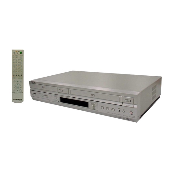
SLV-D940P AZ/D940P EA/D940P ME
SERVICE MANUAL
RMT-V503D
System
Laser
Semiconductor laser
Signal format system
PAL/(NTSC), MESECAM
Channel coverage
SLV-D940P AZ
B/G:VHF E2 to E12/UHF E21 to E69/
CATV S01 to S05, S1 to S41
B/B: VHF R1 to R12/UHF R21 to R69
SLV-D940P ME/EA
B/G:VHF E2 to E12/UHF E21 to E69/
CATV S01 to S05, S1 to S41
D/K: VHF R1 to R12/UHF R21 to R69
I: VHF SA4 to SA13/UHF B21 to B69/
CATV S01 to S05, S1 to S41
RF output signal
UHF channels 21 to 69 (B/G, D/K, I)
UHF channels 28 to 69 (B/B)
Aerial out
75-ohm asymmetrical aerial socket
SLV-D940P AZ
SPECIFICATIONS
Tape speed
SP: PAL
23.39 mm/s (recording/playback)
NTSC 33.35 mm/s (recording*(line input
only)/playback)
LP: PAL
11.70 mm/s (recording/playback)
NTSC 16.67 mm/s (playback only)
EP: NTSC 11.12 mm/s (recording*(line input
only)/playback)
* SLV-D940P ME/EA only
Maximum recording/playback time
10 hrs. in LP mode (with E300 tape)
Rewind time
Approx. 1 min. (with E180 tape)
Inputs and outputs
LINE IN 1/LINE-2 IN
VIDEO IN, phono jack (1)
Input signal: 1 Vp-p, 75 ohms, unbalanced, sync
negative
AUDIO IN, phono jacks (2)
Input level: 327 mVrms
Input impedance: more than 47 kilohms
PAL NTSC
Australian Model
New Zealand Model
Middle East Model
SLV-D940P EA/D940P ME
Refer to the SERVICE MANUAL of VHS MECHANI-
CAL ADJUSTMENT MANUAL VII for MECHANICAL
ADJUSTMENTS. (9-921-790-11)
LINE OUT
VIDEO OUT, phono jack (1)
Output signal: 1 Vp-p, 75 ohms, unbalanced,
sync negative
AUDIO OUT, phono jacks (2)
Standard output: 327 mVrms
Load impedance: 47 kilohms
Output impedance: less than 10 kilohms
Additional AUDIO OUT, phono jacks (2)
Standard output: 327 mVrms
Load impedance: 47 kilohms
Output impedance: less than 10 kilohoms
DIGITAL OUT (OPTICAL)
Optical output jack/−18 dBm
(wave length 660 nm)
DIGITAL OUT (COAXIAL)
Phono jack/0.5 Vp-p/75 ohms
— Continued on next page —
VIDEO CASSETTE RECORDER
RMT-V503D
SLV-D940P AZ
TS-10 MECHANISM
DVD PLAYER/
Advertisement
Table of Contents

Related Manuals for Sony SLV-D940P AZ


Summary of Contents for Sony SLV-D940P AZ
-
Page 1: Dvd Player
SLV-D940P AZ/D940P EA/D940P ME RMT-V503D SERVICE MANUAL Australian Model New Zealand Model SLV-D940P AZ Middle East Model SLV-D940P EA/D940P ME TS-10 MECHANISM RMT-V503D SLV-D940P AZ Refer to the SERVICE MANUAL of VHS MECHANI- CAL ADJUSTMENT MANUAL VII for MECHANICAL ADJUSTMENTS. (9-921-790-11) - Page 2 24-hour cycle Timer setting 6 programs (max.) Power back-up Back-up duration: SLV-D940P AZ: up to 6 hours at a time SLV-D940P ME/EA: up to 24 hours at a time General Power requirements SLV-D940P AZ: 220 − 240 V AC, 50 Hz SLV-D940P ME/EA: 110 −...
- Page 3 IC pins, etc. OPERATION. REPLACE THESE COMPONENTS WITH • Usable with ordinary solder SONY PARTS WHOSE PART NUMBERS APPEAR AS It is best to use only unleaded solder but unleaded solder may SHOWN IN THIS MANUAL OR IN SUPPLEMENTS also be added to ordinary solder.
-
Page 4: Table Of Contents
TABLE OF CONTENTS Precautions The Table of Cleaning, Lubrication and Replacement Time about Principal Parts ························ 2-21 Safety Precautions ·································································· 5 DVD Deck ······································································· 2-22 Servicing Precautions ···························································· 7 2-6-1 Tray Disc Removal ·························································· 2-22 ESD Precautions ····································································· 8 2-6-2 Ass’y P/U Deck Removal ··············································· 2-23 Handling the Optical Pick-up ·················································... -
Page 5: Precautions
PRECAUTIONS 1 SAFETY PRECAUTIONS 1) Before returning an instrument to the customer, always make a (4) Insulation Resistance Test Cold Check-(1) Unplug the power safety check of the entire instrument, including, but not limited supply cord and connect a jumper wire between the two prongs of to, the following items: the plug. - Page 6 6) Product Safety Notice-Some electrical and mechanical parts have special safety-related characteristics which are often not evident from visual inspection, nor can the protection they give necessarily be obtained by replacing them with components rated for higher voltage, wattage, etc. Parts that have special safety characteristics are identified by shading, an ( ) or a ( ) on schematics and...
-
Page 7: Servicing Precautions
2 SERVICING PRECAUTIONS CAUTION: Before servicing units covered by this service manual and its supplements, read and follow the Safety Precautions section of this manual. Note: If unforseen circumstances create conflict between the following servicing precautions and any of the safety precautions, always follow the safety precautions. -
Page 8: Esd Precautions
3 ESD PRECAUTIONS Electrostatically Sensitive Devices (ESD) Some semiconductor (solid state) devices can be damaged easily by static electricity. Such components commonly are called Electrostatically Sensitive Devices (ESD). Examples of typical ESD devices are integrated circuits and some field-effect transistors and semiconductor chip components. The following techniques should be used to help reduce the incidence of component damage caused by static electricity. -
Page 9: Handling The Optical Pick-Up
4 HANDLING THE OPTICAL PICK-UP The laser diode in the optical pick up may suffer electrostatic breakdown because of potential static electricity from clothing and your body. The following method is recommended. (1) Place a conductive sheet on the work bench (The black sheet used for wrapping repair parts.) (2) Place the set on the conductive sheet so that the chassis is grounded to the sheet. -
Page 10: Pick-Up Disassembly And Reassembly
5 PICK-UP DISASSEMBLY AND REASSEMBLY 5-1 Disassembly 5-2 Assembly 1) Replace the Pick-up. 1) Remove the power cord. 2) Remove the soldering 2 points on Pick-up. 2) Disassemble the Deck-Assy. 3) Reassemble the Deck-Assy. 3) Make solder land 2 points short on Pick-up. (See Fig. -
Page 11: General
DVD·VIDEO, then press SELECT VIDEO and point at the remote sensor at the DVD-VCR The instructions in this manual are for the 3 models: SLV-D940P AZ, SLV-D940P ME and your TV TV and point at the remote sensor at your TV SLV-D940P EA. - Page 12 Connect the mains lead to the mains. If the picture does not appear clearly on the TV, change the RF channel on the DVD- SLV-D940P AZ VCR and TV. Select “Install” in the “OPTION” menu, then press V/v to select ENTER “Video Output CH.”...
- Page 13 Step 5 : Selecting a language Step 6 : Setting the clock You can change the on-screen display You must set the time and date on the DVD- SET UP language. VCR to use the timer features properly. SET UP Before you start…...
- Page 14 Press V/v to select “TV System,” then press B/b to select the appropriate Step 8 : Presetting channels TV system. ENTER SLV-D940P AZ If some channels could not be preset using Select the Auto Set Up function, you can preset them manually.
- Page 15 Disabling unwanted programme positions Press V/v to select “Install,” then press INSTALL After presetting channels, you can disable ENTER. Auto Setup unused programme positions. The disabled ENTER Manual Setup The “INSTALL” menu appears. TV System positions will be skipped later when you CH68 Video Output CH press the PROG +/–...
-
Page 16: Basic Operations
Basic Operations Press V/v to select the row which you want to Playing discs MANUAL TUNING change or enter the station name, then press b. SYSTEM ENTER To display other pages for programme – Depending on the disc, some operations may positions 6 to 80, press v/V repeatedly. - Page 17 Notes • You can change the screen type using the “SCREEN SETUP” menu. (See “Screen Setup” on Guide to the on-screen display page 61.) • Do not perform VIDEO playback while playing back a disc. • If you play a DVD or VIDEO CD that has scratches, the player may stop playback at the point of the scratch or skip to the next track.
-
Page 18: Playing A Tape
Locking the disc tray Playing a tape (Child Lock) Before you start... • Turn on the DVD-VCR and your TV. You can lock the disc tray so that the disc tray SELECT DVD • Set your TV to the video channel so that is not opened by mistake. -
Page 19: Recording Tv Programmes
Notes • Tapes recorded in the LP mode on other VCRs can be played back on this VCR but the Recording TV programmes picture quality cannot be guaranteed. • The counter resets to “0:00:00” whenever a tape is reinserted. Before you start... •... - Page 20 Set the programme position, date, start and Recording TV programmes using the timer PR DATE START STOP SPEED stop times and tape speed: ENTER Press b to select each item in turn. Press V/v to set each item. To correct a setting, press B to return to that You can preset up to six programmes at a CLEAR SET UP...
- Page 21 Press EASY TIMER to set the start time. Turn EASY TIMER to set the recording stop time. EASY TIMER EASY TIMER “START” and the next quarter hour increment appear alternately in the You can set the recording stop time in 15 minute intervals or adjust the time display window.
-
Page 22: Advanced Hookups
Press ENTER to confirm the setting. Checking/changing/cancelling timer ENTER settings Before you start… Press ENTER to confirm all settings. • Check that the DVD-VCR clock is set to If any settings remain, turn off the VCR to return to recording standby. the correct time. -
Page 23: Dvd Settings And Adjustments
In case of progressive scan picture problems, it is recommended that you switch the connection to the standard definition output. If there are questions regarding your Sony set’s compatibility with this DVD player, please contact our customer service center. -
Page 24: Screen Setup
• Audio DRC (Dynamic Range Control) Screen Setup Makes the sound clear when the volume is turned down when playing a DVD that conforms to “Audio DRC.” This affects the output from the following jacks: – OUT AUDIO L/R jacks “Screen Setup”... -
Page 25: Setting The Display Or Sound Track
• The “Progressive” setting can be canceled in stop mode by pressing X on the unit Setting the display or sound track continuously for 5 seconds or more, or selecting “Off” in step 2. language Note • If you select progressive signal when you connect the DVD player to a TV that cannot accept the signal in progressive format, the image quality will deteriorate. -
Page 26: Dvd Additional Operations
Press SET UP to exit the menu. SET UP Press b to select “Yes.” • If you have not entered a password To change the password CREATE PASSWORD ENTER The display for registering a new password Enter Password appears. Select “Change Password” in step 4 on page 68. Enter a 4-digit password using the number –... -
Page 27: Zooming Into A Scene
Zooming into a scene Changing the angles You can zoom into a scene during playback If various angles (multi-angles) for a scene ZOOM or still mode. are recorded on the DVD, “ ” appears in Number To zoom into a JPEG image, see “Playing the display when you press ANGLE during buttons JPEG image files”... - Page 28 Playing in random order (Shuffle play) Press B/b to select “PROGRAM,” then press PROGRAM You can shuffle the playback order of tracks. ENTER. Track Program Order Subsequent “shuffling” may produce a CLEAR ENTER – – – – – – – – –...
-
Page 29: Changing The Sound
Changing the sound Virtual surround setting When playing a DVD recorded in multiple When you connect a stereo TV or 2 front audio formats (PCM, Dolby Digital, MPEG speakers, SURROUND lets you enjoy or DTS), you can change the audio format. If surround sound effects by using sound SURROUND AUDIO... - Page 30 Notes Press V/v to select “MP3,” then press Repeat mode • Only the letters in the alphabet and numbers can be used for album or track names. Anything ENTER. Elapsed playing time else is displayed as an asterisk. ENTER The first track starts playing. Press x if •...
-
Page 31: Playing Jpeg Image Files
Press ./> to select the next/previous album page, then press V/v/ Playing JPEG image files B/b to select an image in the “Album” display. To display the selected image You can play JPEG image files on DATA CDs (CD-ROMs/CD-Rs/CD-RWs). Press ENTER. The selected image number appears in the IMAGE display window. -
Page 32: Vcr Additional Operations
Press ENTER. Playing VIDEO CDs with “PBC On/Off” ENTER functions The PBC (Playback control) function allows Follow the instructions in the menu for interactive operations. you to search and perform other operations Number Refer to the instructions supplied with the disc, as the operating procedure interactively. -
Page 33: Recording Stereo And Bilingual
To select the sound while recording Recording stereo and bilingual Press AUDIO to select the sound you want. programmes Stereo programmes To listen to On-screen display Display window In the ZWEITON (German stereo) system Stereo NICAM, STEREO STEREO This VCR automatically receives and records stereo and bilingual programmes based Left channel NICAM, LCH STEREO... -
Page 34: Adjusting The Picture
To search a specific recording (Index search) Adjusting the picture (tracking) Insert an indexed tape into the VCR. Adjusting the tracking Press INDEX, then press m/M twice. Although the VCR automatically adjusts the REPEAT/ tracking when playing a tape, distortion may INDEX •... - Page 35 Press B/b to change the setting. Editing ENTER How to connect to record on this VCR Connect the line outputs of the other VCR to the input connector of this VCR. Refer to the Press SET UP to exit the menu. examples A through B and choose the connection that best suits your VCR.
-
Page 36: Additional Information
There is no picture/picture noise • Re-connect the connecting cord securely. appears. If you have any questions or problems not covered below, please consult your nearest Sony • The connecting cords are damaged. service facility. • Check the connection to your TV (page 11) and switch the input selector on your TV so that the signal from the player appears on the TV screen. - Page 37 Troubleshooting). Clean the video heads using a Sony extension “.JPG” or “.JPEG.” video head cleaning cassette. If a Sony cleaning cassette • Length or width of the image is more than 4720 dots. is not available in your area, have the heads cleaned at The title of the MP3 audio album/ •...
-
Page 38: Index To Parts And Controls
Interlace format Glossary Interlace format shows every other line of an image as a single “field” and is the standard method for displaying images on television. Chapter (page 33) DVD (page 6) The even number field shows the even Sections of a picture or a music feature that A disc that contains up to 8 hours of moving numbered lines of an image, and the odd are smaller than titles. - Page 39 A Z (open/close) button (29) (30) Rear panel Remote commander for DVD B TV / DVD·VIDEO switch (9) C SELECT DVD button (9) D Number buttons* (10) (68) E CLEAR button (26) (76) F SURROUND button (81) G SET UP button (14) H SUBTITLE button (74) I AUDIO button* (80) SKIP button (30)
- Page 40 Index Numerics 16:9 62 Index scan 99 Recording 41 4:3 Letter Box 62 Instant Advance 30 daily/weekly 45 4:3 Pan Scan 62 Instant Replay 30 quick timer recording 94 Instant Skip 38 saving 43 using EASY TIMER 47 Adjusting Repeat play 78 picture 101 JPEG 6 RF channel 13...
-
Page 41: Disassembly And Reassembly
SLV-D940P AZ/D940P EA/D940P ME 2. DISASSEMBLY AND REASSEMBLY 2-1 CABINET AND PCB 2-1-1 Cabinet Top Removal 2-1-3 Ass’y Front Panel Removal 2 Lift up the Cabinet Top in the direction of arrow. 1 REMOVE 1 RELEASE 4 HOOKS 3 SCREWS (Top View) Fig. -
Page 42: Chassis Removal
2-1-5 Chassis Removal 2 REMOVE 4 SCREWS 1 REMOVE 2 SCREWS VCR DECK 3 REMOVE 3 SCREWS 5 REMOVE 3 SCREWS DVD DECK 4 REMOVE 2 SCREWS VCR MAIN PCB DVD MAIN PCB 6 REMOVE 1 SCREW FUNCTION PCB Fig. 2-5 Chassis Removal 2-1-6 VCR Main PCB Removal 1 REMOVE 4 SCREWS VCR MAIN PCB... -
Page 43: Circuit Board Locations
2-2 CIRCUIT BOARD LOCATIONS Fig. 2-7 Circuit Board Locations... -
Page 44: Vcr Deck Parts Locations
2-3 VCR DECK PARTS LOCATIONS 2-3-1 Top View Fig. 2-8 Top parts Location-1 1 GEAR FL CAM 2 MOTOR LOADING ASS’Y 3 LEVER FL ARM ASS’Y 4 HOLDER FL CASSETTE ASS’Y 5 LEVER FL DOOR 6 SLIDER FL DRIVE... - Page 45 qa 0 qs Fig. 2-9 Top Parts Location-2 1 FE HEAD 8 DISK S REEL 2 CYLINDER ASS’Y 9 LEVER S BRAKE ASS’Y 3 ACE HEAD ASS’Y 0 GEAR IDLE 4 LEVER UNIT PINCH ASS’Y qa LEVER IDLE 5 LEVER #9 GUIDE ASS’Y qs LEVER T BRAKE ASS’Y 6 LEVER TENSION ASS’Y qd DISK T REEL...
-
Page 46: Bottom View
2-3-2 Bottom View 1 2 3 Fig. 2-10 Bottom Parts Location 1 GEAR JOINT 1 2 GEAR JOINT 2 3 BRAKET GEAR 4 MOTOR CAPSTAN ASS’Y 5 LEVER T LOAD ASS’Y 6 GEAR LOADING DRIVE 7 LEVER S LOAD ASS’Y 8 HOLDER CLUTCH ASS’Y 9 BELT PULLEY 0 SLIDER CAM... -
Page 47: Vcr Deck
2-4 VCR DECK 2-4-1 Holder FL Cassette Ass’y Removal 2-4-2 Lever FL Door Removal 1) Pull the Holder FL Cassette Ass’y 1 to the eject position. 1) Release the Hook 2 and Remove the Lever FL Door 1 in the 2) Pull the Holder FL Cassette Ass’y 1 as grasping the Holder FL direction of arrow “A”. -
Page 48: Slider Fl Drive, Gear Fl Cam Removal
2-4-3 Slider FL Drive, Gear FL Cam Removal 2-4-4 Lever FL Arm Ass’y Removal 1) Pull the Slider FL Drive 1 to the front direction. 1) Push the hole “A” in the direction of arrow “B” use the pin.(about 2) Remove the Slider FL Drive 1 in the direction of arrow. (Refer to Dia. -
Page 49: Gear Worm Wheel Removal
2-4-5 Gear Worm Wheel Removal 2-4-6 Cable Flat Removal 1) Remove the Gear Worm wheel 1. 1) Remove the Drum connecting part of Cable Flat 1 from Connector Wafer 2. 2) Remove the Loading Motor connecting part of Cable Flat 1 from Connector Wafer 3. -
Page 50: Motor Loading Ass'y Removal
2-4-7 Motor Loading Ass’y Removal 2-4-8 Bracket Gear, Gear Joint 2, 1 Removal 1) Remove the Screw 1. 1) Remove the Screw 1. 2) Remove the Motor Loading Ass’y 2. 2) Remove the Bracket Gear 2. 3) Remove the Gear Joint 2 3. 4) Remove the Gear Joint 1 4. -
Page 51: Gear Loading Drive, Slider Cam
2-4-9 Gear Loading Drive, Slider Cam, 2-4-10 Gear Loading Drive, Slider Cam, Lever Load S, T Ass’y Removal Lever Load S, T Ass’y Assembly 1) When reinstalling, be sure to align dot of Lever T Load Ass’y 1 1) Remove the Belt Pulley. (Refer to Fig. 2-38) 2) Remove the Gear Loading Drive 1 after releasing Hook [A] in with dot of Lever S Load Ass’y 2 as shown in drawing, (Refer to the direction arrow as shown in detail drawing. -
Page 52: Lever Pinch Drive, Lever Tension Drive Removal
2-4-11 Lever Pinch Drive, 2-4-12 Lever Tension Ass’y, Lever Tension Drive Removal Band Brake Ass’y Removal 1) Remove the Lever Pinch Drive 1, Lever Tension Drive 2. 1) Remove the Lever Brake S Ass’y (Refer to Fig 2-25). 2) Remove the Spring Tension Lever 1. 3) Rotate stopper of Main Base in the direction of arrow “A”. -
Page 53: Lever Brake S, T Ass'y Removal
2-4-13 Lever Brake S, T Ass’y Removal 2-4-14 Gear Idle Ass’y Removal 1) Release the Hook [A] and the Hook [B], [C] in the direction of 1) Push the Lever Idle 1 in the direction of arrow “A”, “B”. 2) Lift the Lever Idle 1. arrow as shown in Fig 2-25. -
Page 54: Disk S, T Reel Removal
2-4-15 Disk S, T Reel Removal 2-4-16 Holder Clutch Ass’y Removal 1) Lift the Disk S, T Reel 1, 2. 1) Remove the Washer Slit 1. 2) Lift the Holder Clutch Ass’y 2. Note: When you reinstall Holder Clutch Ass’y 1 DISK S REEL 1) Check the condition of spring as shown in detail A. -
Page 55: Guide Cassette Door Removal
2-4-17 Lever Up Down Ass’y, Gear Center 2-4-18 Guide Cassette Door Removal Ass’y Removal 1) Lift the Hook [A]. 2) Rotate the Guide Cassette Door 1 in the direction of arrow. 1) Remove the 2 hooks in the direction of arrow as shown Fig. 2-29 and lift the Lever Up Down Ass’y 1. -
Page 56: Lever Unit Pinch Ass'y, Plate Joint
2-4-19 Lever Unit Pinch Ass’y, Plate Joint, 2-4-20 Lever #9 Guide Ass’y Removal Spring Pinch Drive Removal 1) Remove the Spring #9 Guide 1. 2) Lift the Lever #9 Guide Ass’y 2 in the direction of arrow “A”. 1) Lift the Lever Unit Pinch Ass’y 1. 2) Remove the Plate Joint 2 from Lever Pinch Drive. -
Page 57: Fe Head Removal
2-4-21 FE Head Removal 2-4-22 ACE Head Removal 1) Lift the FE Head 1. 1) Pull out the FPC from connector of ACE Head Ass’y 2. 2) Remove the Screw 1. 3) Lift the ACE Head Ass’y 2. 1 SCREW 1 FE HEAD 2 ACE HEAD ASS'Y Fig. -
Page 58: Slider S, T Ass'y Removal
2-4-23 Slider S, T Ass’y Removal 2-4-24 Plate Ground Deck, Cylinder Ass’y Removal 1) Move the Slider S, T Ass’y 1, 2 to slot, and then lift it to remove. 1) Remove the 3 Screws 1. (Refer to arrow) 2) Lift the Plate Ground Deck 2. 3) Lift the Cylinder Ass’y 3. -
Page 59: Belt Pulley Removal
2-4-25 Belt Pulley Removal 2-4-26 Motor Capstan Ass’y Removal 1) Remove the Belt Pulley 1. 1) Remove the 3 Screws 1. 2) Remove the Motor Capstan Ass’y 2. Note: Take extreme care not to get grease on Belt Pulley 1 at Assembly: assembling or reassembling. -
Page 60: Post #8 Guide Ass'y Removal
2-4-27 Post #8 Guide Ass’y Removal 2-4-29 How to Eject the Cassette Tape (If the unit does not operate on condition 1) Rotate the Post #8 Guide Ass’y 1 in the direction of arrow to lift that is inserted into housing ass’y) 1) Turn the Gear worm 1 clockwise with screw driver.(Refer to arrow) (Other method: Remove the Screw of Motor Load Ass’y, Separate... -
Page 61: The Table Of Cleaning, Lubrication And Replacement Time About Principal Parts
2-5 THE TABLE OF CLEANING, LUBRICATION AND REPLACEMENT TIME ABOUT PRINCIPAL PARTS 1) The replacement time of parts is not life of parts. 2) The table 2-1 is that the VCR Set is in normal condition (normal temperature, normal humidity). The checking period may be changed owing to the condition of use, runtime and environmental conditions. -
Page 62: Dvd Deck
2-6 DVD DECK 2-6-1 Tray Disc Removal 1) Insert a Screw Driver 1 into Emergency Hole 2 and push the Slider Housing 3 in the direction of arrow “A”. 2) When the Tray Disc 4 comes out a little, pull it in the direction arrow “B” by hand. 3) Pull the Tray Disc 4 to disassemble, while simultaneously pushing 2 Stoppers 5 (left, right) in the direction arrow “C”, “D”. -
Page 63: Ass'y P/U Deck Removal
2-6-2 Ass’y P/U Deck Removal 1) Disconnect DCN2 1 DCN3 2. 2) Lift down the Ass’y P/U Deck 3 while simultaneously pushing 2 Hooks 4, 5 in the direction arrow “A”, “B”. 4 HOOK "A" "B" 5 HOOK <Assembly Point> 1 DCN2 3 ASS'Y-P/U DECK 2 DCN3... -
Page 64: Housing Ass'y Removal
2-6-3 Housing Ass’y Removal 1) Remove Belt 1. 2) Push the Hook 2 in the direction arrow “A” and lift up Pulley Gear 3. 3) Push the Slider Housing 5 in the direction arrow “B” and lift up the Gear Tray 4. 4) Lift up the Slider Housing 5. -
Page 65: Sub Chassis Removal
2-6-4 Sub Chassis Removal 1) Remove the Soldering of Motor Feed (+, - wire) 1. 2) Remove the 4 Screws 2. 3) Lift up the Ass’y Brkt Deck 3. 2 4 SCREWS 3 ASS'Y-BRAK DECK 1 SOLDERING OF MOTOR FEED (+, - WIRE) Fig. -
Page 66: Ass'y Brkt Deck Removal
2-6-5 Ass’y Brkt Deck Removal 1) Push the Hook 1 in the direction arrow “A”and lift up the Gear Feed B 2. 2) Remove 3 Screws 3 and 3 Holder Cam Skew 4. 3) Remove Shaft Pick-Up 5 and Pick-Up Ass’y 6. 4) Remove Gear Feed A 7. -
Page 67: Block Diagram
SLV-D940P AZ/D940P EA/D940P ME 3. Block Diagram... - Page 68 MEMO 3-4E...
-
Page 69: Pcb Diagrams
SLV-D940P AZ/D940P EA/D940P ME 4. PCB Diagrams 4-1 VCR Main - - - - - - - - - - - - - - - - - - - - - - - - - - - - - - - - - - - - - - - - - - - - - - 4-3... -
Page 70: Vcr Main
4-1 VCR Main COMPONENT SIDE... - Page 71 CONDUCTOR SIDE...
-
Page 72: Dvd Main
4-2 DVD Main COMPONENT SIDE... - Page 73 CONDUCTOR SIDE 4-10...
-
Page 74: Dial
4-3 Dial 4-4 FUNCTION 4-11 4-12E... -
Page 75: Schematic Diagrams
SLV-D940P AZ/D940P EA/D940P ME 5. Schematic Diagrams VCR Main PCB 5-1 S.M.P.S. - - - - - - - - - - - - - - - - - - - - - - - - - - - - - - - - - - - - - - - - - - - - - 5-3... - Page 76 5-1 S.M.P.S.
-
Page 77: Power Drive
5-2 Power Drive... -
Page 78: Osd/Vps/Pds
5-3 OSD/VPS/PDS... -
Page 79: A2/Nicam
5-4 A2/NICAM 5-10... - Page 80 5-5 A/V 5-11 5-12...
-
Page 81: Hi-Fi
5-6 Hi-Fi 5-13 5-14... - Page 82 5-7 TM 5-15 5-16...
- Page 83 5-8 I/O 5-17 5-18...
-
Page 84: Syscon
5-9 SYSCON 5-19 5-20... -
Page 85: Logic/Function
5-10 Logic/Function 5-21 5-22... -
Page 86: Dvd A/V
5-11 DVD A/V 5-23 5-24... -
Page 87: Dvd Decoder Servo
5-12 DVD decoder Servo 5-25 5-26... - Page 88 MEMO 5-28E...
-
Page 89: Alignment And Adjustments
SLV-D940P AZ/D940P EA/D940P ME 6. ALIGNMENT AND ADJUSTMENTS 6-1 VCR ADJUSTMENT 6-1-1 Reference 1) X-Point (Tracking center) adjustment, “Head switching adjustment” and “NVRAM option setting” can be adjusted with remote control. 2) When replacing the Main PCB Micom (IC601) and NVRAM (IC605: EEPROM) be sure to adjust the “Head switching adjustment” and “NVRAM option setting”. - Page 90 6-1-1(b) TEST location for adjustment mode setting TEST TEST BUTTON Fig. 6-2 VCR Main PCB (Top View)
-
Page 91: Head Switching Point Adjustment
< Table 6-1 NVRAM Option Table > MODEL OPTION NUMBERS SLV-D940P AZ 6, 7, 8, 9, 10, 12, 15, 25, 26, 27, 32, 33, 35, 36, 39, 41, 43, 45, 47, 49, 57, 60, 61, 63, 64, 67, 68, 70, 71 SLV-D940P EA... -
Page 92: Vcr Mechanical Adjustment
6-2 VCR MECHANICAL ADJUSTMENT 6-2-1 Tape Transport System and Adjustment Locations The tape transport system has been adjusted precisely in the factory. Alignment is not necessary except for the following : 1) Noise observed on the screen. 2) Tape damage. 3) Parts replacement in the tape transport system. -
Page 93: Tape Transport System And Adjustment
6-2-2 Tape Transport System Adjustment When parts are replaced, perform the required adjustments by referring to procedures for the tape transport system. If there are any changes to the tape path, first run a T-120 tape and make sure excessive tape wrinkle does not occur at the tape guides. If tape wrinkle is observed at the guide roller S, T, turn the guide roller S, T until wrinkle disappears. - Page 94 b. ACE HEAD TILT ADJUSTMENT 1) Playback a blank tape and observe the position of the tape at the lower flange of tape guide. 2) Confirm that there is no curl or wrinkle at the lower flange of tape guide as shown in Fig. 6-9 (B). 3) If a curl or wrinkle of the tape occurs, slightly turn the screw (A) tilt adjust on the ACE head ass’y.
- Page 95 d. ACE HEAD POSITION (X-POINT) ADJUSTMENT 1) Playback the alignment tape (Color bar) 2) Press the “TEST” botton on VCR MAIN PCB to set the adjustment mode. (See Fig. 6-2) 3) Press the “0, 5” remote control buttons, then adjustment is operates automatically. (See Fig. 6-1) 4) Connect the CH-1 probe to “Envelope”...
- Page 96 (2) Linearity adjustment (Guide roller S, T adjustment) 1) Playback the Mono Scope alignment tape (SP mode). 2) Observe the video envelope signal on an oscilloscope (triggered by the video switching pulse). 3) Make sure the video envelope waveform (at its minimum) meets the specification shown in Fig. 6-9. If it does not, adjust as follows : Note: a=Maximum output of the video RF envelope.
- Page 97 6) Play back the Mono Scope alignment tape (SP mode). 7) Connect an oscilloscope CH-1 to the “Envelope” and CH-2 to the “H’D SW Pulse” for triggering. 8) Turn the guide roller heads with a flat head ( ) driver to obtain a flat video RF envelope as shown in Fig. 6-13. IDEAL ENVELOPE S HEIGHT TOO HIGH T HEIGHT TOO HIGH...
-
Page 98: Reel Torque
(4) Envelope Check 1) Make recordings on T-120 (E-120) and T-160 (E-180) tape. Make sure the playback output envelope meets the specification as shown in Fig. 6-15. 2) Play back a self recorded tape (recording made on the unit using with T-120 (E-120). The video envelope should meet the specification as shown in Fig. -
Page 99: Troubleshooting
SLV-D940P AZ/D940P EA/D940P ME 7. TROUBLESHOOTING... - Page 108 7-10...
- Page 109 7-11...
- Page 110 7-12...
- Page 111 7-13...
- Page 112 7-14...
- Page 113 7-15...
- Page 114 7-16...
- Page 115 7-17...
- Page 116 MEMO 7-18E...
-
Page 117: Repair Parts List
SLV-D940P AZ/D940P EA/D940P ME 8. REPAIR PARTS LIST 8-1 Exploded Views - - - - - - - - - - - - - - - - - - - - - - - - - - - - - - - - - - - - - - - - -... -
Page 118: Exploded Views
8-1 EXPLODED VIEWS NOTE: • -XX, -X mean standardized parts, so they may • The mechanical parts with no reference number The components identified by mark have some differences from the original one. in the exploded views are not supplied. dotted line with mark are critical for safety. -
Page 119: Vcr Mechanical Parts (Top Side)
8-1-2 VCR Mechanical Parts (Top Side) G001 K490 not supplied not supplied G555 not supplied not supplied G450 G510 G680 not supplied G420 G480 K546 K250 G560 K240 K248 G681 B410 K350 K110 B440 not supplied not supplied K340 not supplied not supplied G546 not supplied... -
Page 120: Vcr Mechanical Parts (Bottom Side)
8-1-3 VCR Mechanical Parts (Bottom Side) G542 B462 not supplied not supplied B560 not supplied not supplied not supplied not supplied not supplied supplied not supplied not supplied not supplied not supplied not supplied not supplied not supplied B570 Ref. No. Part No. -
Page 121: Dvd Mechanical Parts
8-1-4 DVD Mechanical Parts not supplied supplied H205 H900 H204 H202 H903 H903 H210 H241 H211 H207 H206 H206 H904 H904 H203 not supplied not supplied H105 H106 H903 H103 H108 H104 not supplied DSW1 The components identified by mark dotted line with mark are critical for safety. -
Page 122: Electrical Parts List
DIAL DVD MAIN FUNCTION 8-2 ELECTRICAL PARTS LIST • Items marked “*” are not stocked since they are NOTE: When indicating parts by reference number, • Due to standardization, replacements in the seldom required for routine service. Some delay please include the board name. parts list may be different from the parts should be anticipated when ordering these items. - Page 123 FUNCTION VCR MAIN Ref. No. Part No. Description Remarks Ref. No. Part No. Description Remarks SW714 9-885-056-38 TACT SWITCH (CH UP) D1SS11 1-804-408-11 DIODE UF4007 D1SS12 9-885-067-34 DIODE SRAF560 SW716 9-885-056-38 TACT SWITCH (POWER) D1SS13 9-885-067-34 DIODE SRAF560 D1SS14 9-885-067-34 DIODE SRAF560 D1SS15 1-804-412-11 DIODE F1T4 VCR MAIN BOARD D1SS16 1-804-411-11 DIODE UG2D...
- Page 124 VCR MAIN Ref. No. Part No. Description Remarks Ref. No. Part No. Description Remarks 0 IC1S02 1-804-440-11 PHOTO COUPLER Q6P02 1-804-420-11 TRANSISTOR KSA733 Q6P04 1-804-421-11 TRANSISTOR KSC945 IC1S03 1-804-445-11 IC KA4318 Q891A 1-804-421-11 TRANSISTOR KSC945 IC1SS2 9-885-037-01 IC (PWM CONTROLLER) IC4N01 1-804-795-11 IC (NICAM) Q891B 1-804-421-11 TRANSISTOR KSC945...
- Page 125 SLV-D940P AZ/D940P EA/D940P ME Sony Corporation 2004H0500-1 Home Electronics Network Company ©2004. 8 — 148 — 9-874-831-11 Published by Quality Assurance Dept.
Need help?
Do you have a question about the SLV-D940P AZ and is the answer not in the manual?
Questions and answers