Table of Contents
Advertisement
Quick Links
Advertisement
Table of Contents

Related Manuals for JR ProPo 28X


Summary of Contents for JR ProPo 28X
-
Page 3: Table Of Contents
▋Contents Home Screens 3-11 3-12 About items and widgets ▊ Introduction Adding items to the home screen 3-13 ▊ Removing items from the home screen 3-13 Features Grouping items 3-13 Safety Information Submenu (home/application selection screens) 3-14 ▊ General▊Information ▊ 3-14 Wallpaper Introduction to the Transmitter 3-14 System settings Mixing curve 3-15 Antenna Changing values 3-15 Stick length adjustment Neck strap attachment What are the function and system lists? 3-16 Cleaning the transmitter and screen 3-16 Airplane function and system lists Turning the transmitter on 3-17 Helicopter function and system lists Warning display 3-17... - Page 4 THROTTLE MIX 4-23 STICK ACCELERATOR 5-20 FLAP SYSTEM 4-24 ALL SERVO HOLD 5-21 SNAP ROLL 4-25 X BUS FUNCTIONS 5-22 DIFFERENTIAL 4-26 ▊ Telemetry▊System▊ ▊ AILERON TO RUDDER MIX 4-28 ▊ Other▊Android▊Functions AILERON TO FLAP MIX 4-29 ▊ ELEVATOR TO FLAP MIX 4-31 Browser RUDDER TO AILERON/ELEVATOR MIX 4-33 Calculator GEAR CONTROL 4-35 Downloads OUTPUT CURVE 4-36 Gallery FLAP RATE 4-37 Music MOTOR SYSTEM 4-39 OI file manager CAMBER SYSTEM...
-
Page 5: Introduction
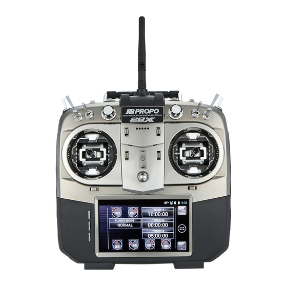
Integrated touch screen android interface was previously unknown to the user) to be monitored on the transmitter. The 28X is the first RC system to offer an Android operating system. This In addition, alarms with unique sounds alert the user to the situation on technology is accessible through a 480 x 273 pixel, 4.3"... -
Page 6: Safety Information
▋Safety Information DANGER JR Propo cannot be held responsible for any accident or failure that may occur due to any modification of this product, use of non-genuine parts, If incorrect operation methods are used, it may result in death or natural disaster, or nonobservance of the precautions described in this serious injury. - Page 7 Introduction The engine or motor (in the case of an electrically-driven model) Is there enough battery charge remaining in the transmitter and can start rotating at high speed, causing danger. receiver? When turning on the power switch, set the transmitter throttle stick to Is there any fuel spillage on the receiver, servos, etc.
- Page 8 Introduction The rechargeable battery is composed several individual batteries. Note that the actual battery level cannot be precisely confirmed by testers such as a battery checker. Check the state of charge in a comprehensive way by using a battery checker, checking the recharge time, and operating time.
-
Page 9: General▊Information
▋ For added comfort and stability during Your new JR 28X will provide years of reliable service. To get the best use, you may choose to use a neck strap. performance from your new transmitter, please be sure to fully understand all its controls and functions. -
Page 10: Unlocking The Screen
General▋Information ▋Inserting▋and▋removing▋the▋SD▋card ▋ ▋Unlocking▋the▋screen For maximum compatibility and ▋ reliability, we recommend you If the screen lock has been activated, simply swipe the padlock icon toward purchase a JR branded SD card. the top of the screen. If you choose to use a third party card, please ensure it is less than 32GB in size, and formatted in FAT. -
Page 11: Inserting And Removing The Transmitter Batteries
④ When fitting new batteries, be sure to only use JR genuine replacement located under this cover. Please Li-Ion packs designed for the 28X. Carefully fit the battery power refer to page 2-3 for information connector and temperature sensor lead. Ensure that the battery power on charging the transmitter. -
Page 12: Voice Prompts
▋RG712BX▋receiver ▋ ※ Be certain to only use the genuine JR 28X dedicated power adapter. The transmitter may be supplied as a combo with a 7 channel antenna Charging is not possible using other adapters. Further, do not use this diversity receiver –... - Page 13 General▋Information Mode 1 CH3 Elevator CH1 Throttle CH4 Rudder CH2 Aileron Mode 2 CH1 Throttle CH1 Throttle CH3 Elevator CH3 Elevator CH4 Rudder CH4 Rudder CH2 Aileron Mode 3 CH3 Elevator CH3 Elevator CH1 Throttle CH2 Aileron CH2 Aileron CH4 Rudder CH4 Rudder Mode 4 CH1 Throttle...
-
Page 14: Stick Spring Tension And Travel Adjustment
General▋Information ▋Stick spring tension and travel adjustment feel from smooth clutch to ratchet. ▋Stick▋spring▋tension▋adjustment ▋ Never touch the printed circuit board or any related parts inside the Remove the batteries before carrying out any adjustments. transmitter. Remove the molded rubber sections from the back of the transmitter. Touching the board may result in electric shock, uncontrolled microcomputer operation, or damage to model data, and normal operation may become ... -
Page 15: Functions▊Common▊To▊All▊Models
Functions▋Common▋to▋All▋Models increases the pressure on the throttle clutch, as either a smooth feel or channel setting function. ratchet. Do not dismantle the transmitter. 4) Adjust the pressure to the desired strength, while testing the throttle Doing so may cause an electrical shock, a microcomputer crash, and damage to model data, resulting in a product that does not function or stick feel. -
Page 16: Changing The Stick Horizontal Angle Control Blocks
Functions▋Common▋to▋All▋Models stick calibration (see page 5-10). 6) After changing the position of the horizontal angle control blocks, be sure to carry out stick calibration (see page 5-10). ※ When turning on the transmitter, a warning may be issued after replacing the blocks. To release the warning status, display the warning ▋Removing and installing the stick switch screen, touch "setting", and increase the numeric value for the position of the throttle stick. -
Page 17: Operating The Stick Switch
Functions▋Common▋to▋All▋Models ▋ 1) Insert the stick switch while keeping the notch surface 1 and the notch ▋Removing▋and▋installing▋the▋stick▋head▋for▋the▋stick▋switch surface 2 aligned with the hole for the socket screw A . Remove the socket screw. Forcefully pushing the stick switch may cause damage to the equipment. ... -
Page 18: Receiver Connections
Functions▋Common▋to▋All▋Models ▋Receiver connections If the connectors become detached while flying, there will be a risk of the model crashing. Please securely insert all connectors as far as they will go. ▋Receiver▋connections▋to▋the▋servos▋and▋the▋power▋supply ▋ If extension leads are used during installation, sticky tape should be The channels on the receiver are labeled with names rather than numbers. -
Page 19: List Of Receiver Connecting Channels
Functions▋Common▋to▋All▋Models ▋2.4GHz RF characteristics ▋List▋of▋receiver▋connecting▋channels ▋ The 2.4GHz band radio waves are very directional. The receiver signal is Receiver Helicopter Airplane Glider 1) THRO very dependent on the direction of the transmitter and receiver antenna. THRO THRO LAIL Since the antenna receives radio waves from the sides rather than from the 2) AILE AILE AILE... - Page 20 Functions▋Common▋to▋All▋Models ▋Receiver▋antenna▋considerations ▋ 2.4GHz band radio waves have strong Weak Signal directionality so receiving sensitivity differs greatly depending on the Strong Strong Reception Reception direction of antenna orientation. RG712BX Receiver The antenna part should be installed in a perfectly straight condition. Coaxial part of the antenna can be bent however, do not bend it in a sharp...
-
Page 21: Binding Procedure
Functions▋Common▋to▋All▋Models ▋ ▋Remote▋antenna▋installation receiver (and the remote antenna if purchased) will begin to blink (ready Bind plug to bind). It is possible to use an optional Material Frame r e m o t e a n t e n n a w i t h t h e Receiving Connecting the battery Receiving... -
Page 22: Dmss Ez Bind System
Functions▋Common▋to▋All▋Models ▋ ▋Binding▋method When in this mode, walk a distance of approximately 40m from the aircraft and confirm that the transmitter operates the aircraft normally. Continue To establish communication with a transmitter, binding (pairing) must be testing as you walk around the aircraft. Touch under range check again and carried out. -
Page 23: Transmitter Controls
Functions▋Common▋to▋All▋Models ▋Transmitter Controls Speaker Charge lamp: Battery A Power Switch Charge lamp: Battery B Pilot Lamp (LED) Charging: Green Reset: Yellow During transmission: Blue. During low output transmission/Servo hold: Blue,flashing. Display When radio transmission is stopped: Red. Low battery voltage: Flashing... - Page 24 Functions▋Common▋to▋All▋Models Touch screen Home key Submenu key Menu Back key Carry Handle 2.4GHz Antenna SD Card Slot USB Port Trainer Jack mini USB Port Charge Jack Headphone Jack 3-10...
-
Page 25: Names And Functions Of The Input Keys
Functions▋Common▋to▋All▋Models ▋Names and functions of the input keys Touch screen Touch screen This transmitter employs a touch screen. When programming the transmitter, almost all operations can be performed very intuitively using the touch screen. There are also three standard button keys. Home key If this key is pressed at any time, the transmitter screen returns to the main home screen. -
Page 26: About Items And Widgets
Functions▋Common▋to▋All▋Models ・ Status area Notification/Status bar Status of the model, remaining battery capacity, and other similar information is displayed. ・ Notification area Status of USB, WiFi, etc. is displayed. Dock bar ・ Dock bar The dock bar is a fixed display area. Even if the home screen is changed to another page, contents on the dock bar will remain the same. -
Page 27: Adding Items To The Home Screen
Functions▋Common▋to▋All▋Models ▋Adding items to the home screen ▋Removing items from the home screen 1) Display the home screen where you 1) Touch and hold an icon you would like would like to place an item. to remove so that the icon becomes If there is no space to place the item, movable. -
Page 28: Submenu (Home/Application Selection Screens)
If you touch the software update area, the update will automatically You can select animated wallpaper. begin. Wallpaper You can select an illustration provided by JR Propo. ※ The same wallpaper settings described above can also be performed in the display menu in system settings. ▋System▋settings ▋... -
Page 29: Mixing Curve
Functions▋Common▋to▋All▋Models ▋Mixing curve ▋Changing values The mixing curve is formed by a horizontal axis which represents input (for Popup screen example, the position of a stick or lever on the transmitter) and a vertical Close axis which represents output (actual servo movement). Increase the value ... -
Page 30: What Are The Function And System Lists
Functions▋Common▋to▋All▋Models ▋What are the function and system lists? ▋Airplane▋function▋and▋system▋lists ▋ The function list contains items which you will commonly change during the setup and trimming of your model. Examples here are dual rate and exponential adjustment, differential adjustment, etc. The system list contains items which are set once and then likely to not be changed as you setup the model. -
Page 31: Helicopter Function And System Lists
Functions▋Common▋to▋All▋Models ▋Helicopter▋function▋and▋system▋lists ▋Glider▋function▋and▋system▋lists ▋ ▋ Continuing to swipe the screen will bring up the ‘other’ menu items (page 7-1). These are related to the Android operating system which runs the transmitters input interface. 3-17... -
Page 32: Other
Functions▋Common▋to▋All▋Models ▋New model setup ▋Other ▋ When you create a new model, it is important some basic parameters are defined when you start setting up the model. ▋Airplane ▋ ① Create a new model in the model select menu (page 5-1). Select ‘airplane’ as the aircraft type. Name the Airplane model with a name you can recognize. -
Page 33: Glider
Functions▋Common▋to▋All▋Models ▋Helicopter for linear motor response (page 4-9), change the behavior of the throttle ▋ trim (page 4-21), set up the snap roll function (page 4-25) and continue to Most helicopters on the market are flybarless (FBL), and explore the radio further. each FBL system requires a unique setup. The following Helicopter describes the basic setup of a flybar (FB) helicopter, as it describes many of ▋Glider... -
Page 34: Flight Modes
Functions▋Common▋to▋All▋Models ▋Flight modes directions. Use the servo reverse function (page 4-7) to do this. With most FBL units, you would set the transmitter reverse directions to match the FBL unit. ▋Function▋explanation ▋ ⑩ Next set the servo arms in neutral. The sub trim function (page 4-6) is The flight mode function allows switching between various aircraft settings useful here. -
Page 35: Airplane
Functions▋Common▋to▋All▋Models ▋ ▋Using▋flight▋modes " ▽ " indicates a mode that can be added in flight mode setup. * Priorities for flight modes when conditions are met for several flight modes can be defined in priority settings included in the submenu (see FLIGHT MODE SETUP, page 5-3). -
Page 36: Understanding The Switch Selection Menus
Functions▋Common▋to▋All▋Models ▋Understanding the switch selection ② Analogue position switch (APS) menus Many of the transmitter functions require you to select a switch or input to use for that function. The switch select dialogues are all very similar, and the following describes their logic. ... - Page 37 Functions▋Common▋to▋All▋Models ▋Normal – Possible logics are: Note that the transmitter sticks can be used directly as 3 position switches, or alternatively they can be used as an analogue position switch (page 5-7) with greater flexibility. Multiple switches or stick switches (and positions) can be selected. ...
-
Page 38: Function▊List
Function▋List DUAL RATE & EXPONENTIAL Helicopter ▋Function▋explanation ▋ This function allows different control throw, exponential and user defined definable curve function allows up to 8 user definable points Airplane curve settings for aileron, elevator, rudder, and one auxiliary channel, to be used to create your own curves, rather than use an selectable using switches on the transmitter. - Page 39 Function▋List ▋ ▋Submenu▋functions Return to the previous screen by pressing the back button. ⑤ Next click the switch icon. Here you are able to select from up to Pressing the submenu button provides access to the trim input function, a delay function as well as auxiliary channel selection. 15 switches or combinations of switches to select different D/R and exponential curves which you can define.
- Page 40 Function▋List Finally, you can touch the channel selection to select the next channel to program D/R and exponential settings for. Once you are finished, press the back button twice to return to the home screen. Tips When you are in the switch selection dialogue, it is possible to change the priority of dual rate selection.
-
Page 41: Travel Adjust
Function▋List touching the number for approximately one second. TRAVEL ADJUST ⑥ Return to the previous screen by pressing the back button. Helicopter ⑦ Depending on functions activated, occasionally it will not ▋Function▋explanation ▋ be possible to set travel adjust. For example, any gyro gain channels will only be controlled by the gyro gain menu, Select the channel and travel adjust will not be available. -
Page 42: Limit Adjust
Function▋List set channel limits. For example, any gyro gain channels LIMIT ADJUST will only be controlled by the gyro gain menu, and limit adjust will not be available. Helicopter ⑦ After selecting each channel and setting the limit adjust Select the channel values, return to the home screen by again pressing the back button. -
Page 43: Sub Trim
Function▋List SUB TRIM Tips Helicopter Be sure to only use minimal amounts of sub trim. First Select the channel position the servo arm close to the correct position, and then use sub trim to fine tune as required. Airplane Sub trim amount ... -
Page 44: Reverse Switch
Function▋List ▋Caution▋note REVERSE SWITCH ▋ Important Helicopter Whenever you make changes to the model setup (and reverse switches in particular), please reset the failsafe settings (see page 5-14). For example, if the throttle Airplane failsafe had been set to motor cut, and now the throttle servo is reversed, the failsafe setting will now be for full Current channel direction Confirmation popup... -
Page 45: Servo Speed
Function▋List controlled by the gyro gain menu, and servo speed will not SERVO SPEED be available. ④ Two different servo speed profiles can be selected. First Helicopter select a switch for choosing between these two profiles. Touch the switch icon and select a switch or switches in the usual manner. -
Page 46: Throttle Curve
Function▋List THROTTLE CURVE Helicopter Switch select options Current point Points ADD/DEL Airplane Current Flight Mode position Each adjusting point T h i s c h a n g e s t h e Numerical Display of input position and point connections to the Stick input Position output position a Curve. - Page 47 Function▋List ▋ ▋Submenu▋functions ▋Helicopter Typical helicopter throttle curves may look like this: Normal mode (for hovering) Stunt mode (for 3D) Submenu key Additional submenu features include Delay setting ▋Airplane A delay of 0-10 seconds can be used to smooth transition between various curves.
-
Page 48: Pitch Curve
Function▋List PITCH CURVE Helicopter Switch select options Current point Points ADD/DEL Airplane Current Flight Mode position Each adjusting point T h i s c h a n g e s t h e Numerical Display of input position and point connections to the Stick input Position output position a Curve. - Page 49 Function▋List seconds as required. point, and click on ‘output’ to change the value at that point. ⑧ The position of the points can be fine-tuned by pressing ‘input’, and then Trim input setting This option allows a trim input device (see page 5-8) to be chosen to changing the horizontal position of the point.
-
Page 50: Throttle Hold
Function▋List ▋ ▋Helicopter THROTTLE HOLD ① Before being able to use throttle hold, it is necessary to add a switch to the ‘hold’ flight mode. Please see page Helicopter 5-3. It is possible to use a switch in any desired switch location. - Page 51 Function▋List ▋ ▋Airplane ① This function is ‘inh’ by default. Set the function to ‘act’ by touching ‘inh’ and selecting ‘act’. ② Then enter the hold position value required by touching the value input area and entering a value. ③ The hold switch is used by default, but this selection can be modified by touching the switch icon and selecting an appropriate switch(see page 3-22).
-
Page 52: Gyro Sensitivity
Function▋List GYRO SENSITIVITY Helicopter Airplane ▋Function▋explanation ▋Setting▋method ▋ ▋ This function controls gyro sensitivity using one or more channels as ▋ ▋Helicopter defined in the system menu, channel setting (page 5-15). It allows adjusting ① From the home screen, press the menu button on the touch screen. the gyro sensitivity from the transmitter. - Page 53 Function▋List ▋Two gyro gains gain settings, only ‘triple gyro’ is available. In two gyro mode, the mode can be set to either till lock or normal. In ⑦ Next set the mode – either tail lock or normal. With dual gain, one gyro tail lock mode, T (tail lock) or N (normal) can be selected.
- Page 54 Function▋List ▋ ▋Submenu▋functions This option allows a trim input device (see page 5-8) to be chosen to change any selected gyro gain. The trim input device must first be defined before it can be activated. Calibration for 3 axis gyros (3 gyro mode only) The JR 3 axis gyro system (TAGS01 or TAGSmini) as used for Flybarless R/C helicopters requires calibration prior to flying.
-
Page 55: Governor
Function▋List page 5-15 for help with the channel setting menu. Press GOVERNOR the back button to return to the previous screen. If you have not done this, the following screen will appear. Helicopter Current Flight Mode position ③ From the function list, select governor. Switch select options ④ Next define how many governor speed options you wish to use. -
Page 56: Swash Mix
Function▋List allows the use of an electronic cyclic ring and various swash SWASH MIX correction settings. ▋Setting▋method Helicopter ▋ ① From the home screen, press the menu button on the touch screen. ② It is first necessary to select the swash plate type. Go to the system menu, swash type. - Page 57 Function▋List ⑨ After setting the function, return to the home screen by pressing the mixing amount can be carried out separately to the front and rear and to the left and right. The mix can be switched on and off of using back button.
-
Page 58: Thro Trim
Function▋List back button. THRO TRIM ▋ ▋Throttle▋cut Helicopter ① The throttle cut can be used by setting it to ‘ACT’. Activating this function automatically inhibits the throttle trim offset memory function. Airplane ② Next touch the switch icon, and here you can select the switch or switches to use for this function. - Page 59 Function▋List ④ Next enter a value to (typically) decrease idle speed for landing. This would be entered as a negative value. ⑤ You may also set up a trim input to fine tune the final idle speed. Please first define a trim input device (see page 5-8) and then select the device under trim input.
-
Page 60: Throttle Mix
Function▋List mix function. You will be able to select from aileron, THROTTLE MIX elevator or rudder to throttle mixes. ④ Next touch the switch icon, and here you can select the Helicopter switch or switches to use for selecting each throttle mix option. -
Page 61: Flap System
Function▋List ③ First activate the function. FLAP SYSTEM ④ Next touch the switch icon, and here you can select the switch or switches to use for selecting each flap system Airplane option. Select a switch or switches in the usual manner (see page 3-22). -
Page 62: Snap Roll
Function▋List or just selected flight modes. SNAP ROLL This is done by touching the flight mode area and selecting either ‘on’ (active all the time) or selecting Airplane individual flight modes for the preset to be active in. b. Next you must set the switch to activate the snap roll preset. Touch under ‘snap device’... -
Page 63: Differential
Function▋List ③ First set the number of different differential settings you DIFFERENTIAL wish to use. Touch the POSx area and add presets as required. Use the back button to return to the previous Airplane ▋Function▋explanation screen. ▋ ④ Next touch the switch icon, and here you can select the This function can be used when either the aileron, rudder, and flap channels switch or switches to use for selecting each differential have been set to dual channel (two or more servos are being used for each... - Page 64 Function▋List ▋Break differential function The spoiler stick position can be used to break (remove) any differential Tips settings. The stick can be set to have no effect on differential (0%). You can set any position between 0% and 100% (full spoiler activation) for ...
-
Page 65: Aileron To Rudder Mix
Function▋List all control surfaces when different mix settings are selected. AILERON TO RUDDER MIX Trim input switches can be used to fine tune each of the mix settings in flight. Additionally, a break/hold setting allows Airplane the elevator or rudder stick to turn off the mix Current Flight Mode position Switch select options Points ADD/DEL... -
Page 66: Aileron To Flap Mix
Function▋List ▋ ▋Submenu▋functions AILERON TO FLAP MIX Delay Airplane To avoid sudden changes in the mix, a delay can be utilized (0-10 seconds). This smooth’s the model reaction if rudder mix settings are Current Flight Mode position Switch select options Points ADD/DEL changed. - Page 67 Function▋List ▋ ▋Submenu▋functions generation of air resistance when you wish to speed up the roll rate. The submenu contains a delay function to slow the transition of all control Delay surfaces when different mix settings are selected. Trim input switches can To avoid sudden changes in the mix, a delay can be utilized (0-10 be used to fine tune each of the mix settings in flight.
-
Page 68: Elevator To Flap Mix
Function▋List transition of all control surfaces when different mix settings ELEVATOR TO FLAP MIX are selected. Trim input switches can be used to fine tune each of the mix settings in flight. Airplane Current Flight Mode position Switch select options Points ADD/DEL ▋Setting▋method ▋... - Page 69 Function▋List fine tune any selected mix. The trim input device must first be defined before it can be activated. By using the trim input, it is possible to change the amount of any selected elevator to flap mix using a trim lever. Therefore, it is possible to easily adjust mix settings during flight.
-
Page 70: Rudder To Aileron/Elevator Mix
Function▋List RUDDER TO AILERON/ELEVATOR MIX Airplane surfaces when different mix settings are selected. Trim input Mix select options switches can be used to fine tune each of the mix settings in flight. Current Flight Mode position Switch select options Points ADD/DEL ▋Setting▋method ▋... - Page 71 Function▋List ▋ ▋Submenu▋functions Delay To avoid sudden changes in the mix, a delay can be utilized (0-10 seconds). This smooth’s the model reaction if mix settings are changed. Trim input This option allows a trim input device (see page 5-8) to be chosen to fine tune any selected mix.
-
Page 72: Gear Control
Function▋List same sequence GEAR CONTROL b. Separate mode: In this mode up and down gear and door action can be different. Airplane c. Curve movement can be made slowly. Activating exp makes the curve smooth. Switch select options 'Step' is for a quick movement. Operation time is the servo speed. d. Set the time required from moving from the left to right of the graph. -
Page 73: Output Curve
Function▋List ▋Setting▋method OUTPUT CURVE ▋ ▋Airplane ▋ Helicopter ① From the home screen, press the menu button on the Current channel Points ADD/DEL touch screen. ② From the function list, select output curve. Airplane ③ Select the servo output curve you wish to modify. It is possible to fine tune the output curve for each of the 16 proportional channels. -
Page 74: Flap Rate
Function▋List be used to fine tune each of the mix settings in flight. FLAP RATE ▋Setting▋method Glider ▋ Current channel ① From the home screen, press the menu button on the touch screen. Current Flight Mode position Switch select options Points ADD/DEL ② From the function list, select flap rate. - Page 75 Function▋List ▋ ▋Submenu▋functions Delay To avoid sudden changes in the mix, a delay can be utilized (0-10 seconds). This smooth’s the model reaction if mix settings are changed. Trim input This option allows a trim input device (see page 5-8) to be chosen to fine tune any selected mix.
-
Page 76: Motor System
Function▋List Delays form 0-10 seconds are possible. MOTOR SYSTEM ⑥ After setting the function, return to the home screen by pressing the back button. Glider ▋Caution▋note ▋ Be sure to set the ‘warning’ function in the system list and be aware of the motor starting unexpectedly. -
Page 77: Camber System
Function▋List ▋Setting▋method CAMBER SYSTEM ▋ There are two ways of setting the amount of camber offset in Glider each flight mode. One is to set it using this function, and the other method is changing the camber trims in each flight mode. Using the camber system function, it is possible to set the camber off-set with a desired delay and break function, and also precisely set each control surface. -
Page 78: Brake System
Function▋List ▋ ▋Submenu▋functions BRAKE SYSTEM Break threshold Glider The break threshold setting defines the elevator stick position at which Current channel the delay function is deactivated. Current Flight Mode position Switch select options Points ADD/DEL Tips To prevent unnoticed changes of the camber trim position that has been set in each flight mode, the sensitivity of the camber trim levers can be set to zero. - Page 79 Function▋List You are able to set two different elevator compensation profiles. will see the whole wing will no longer generate lift, and will have a huge amount of drag. A dead band can be set to prevent unintentional operation First touch the switch icon and select the switches to use to activate the if the stick is just moved a small amount.
- Page 80 Function▋List ▋Caution▋note able to delete points by touching delete. The curve output at each point ▋ can be adjusted by moving the spoiler stick to the desired point and When this function is fully operated, the servos will move a considerable touching on ‘output’...
-
Page 81: Flaperon Mix
Function▋List ‘Flap to flaperon’: FLAPERON MIX This mixes from flap to aileron, to use the ailerons as flaps. ‘Flap to elevator’: Glider Mix select options This mixes from flap to elevator, to correct pitch variation Current Flight Mode position Switch select options Points ADD/DEL caused by flap extension. - Page 82 Function▋List ② From the function list, select flaperon mix. The curve output at each point can be adjusted by moving the flap lever to the desired point and touching on ‘output’ and making adjustments as ③ Touch on the function select area, and select ‘aileron to flap’. required.
-
Page 83: Elevator To Camber Mix
Function▋List surfaces when different mix settings are selected. ELEVATOR TO CAMBER MIX Trim input switches can be used to fine tune each of the mix settings in flight. Glider Mix select options ▋Setting▋method ▋ Current Flight Mode position Switch select options Points ADD/DEL The mix amount to the flaps and flaperons can be set on each flight mode, with camber up and down directions set individually. -
Page 84: Rudder To Spoiler Mix
Function▋List Next touch the switch icon and select the switches to use to activate the RUDDER TO SPOILER MIX different profiles. To adjust each profile, either select the desired profile using the assigned switch, or touch the profile area on the screen and Glider select from here. - Page 85 Function▋List The submenu contains a delay function to slow the transition of all control to easily adjust mix settings during flight. surfaces when different mix settings are selected. Trim input switches can It is possible to select which point or points on the curve you would like be used to fine tune each of the mix settings in flight.
-
Page 86: Program Mixing [Prog.mix1-10]
Function▋List specifically set in the channel setting (see page 5-15). PROGRAM MIXING [PROG.MIX1-10] b. Channel number: This allows you to select any one of the 28 channels to Helicopter use as the master for the mix. For example, with a two aileron servo wing, you may decide to use only the output of the left aileron servo to Airplane drive the mix. - Page 87 Function▋List ⑫ Press the back button to return to the previous screen. a. The total mix in each profile is set by touching the required profile (POS 0 or 1). ⑬ Next select if you wish to use a normal mix or the curve mix function. b. Move the master channel to each extreme of travel, and set the total The normal mix only allows adjustment of the endpoints of the mixing mix required.
- Page 88 Function▋List ▋ a. On this screen you are able to adjust how the mix responds in a very ▋Items▋which▋can▋be▋"INCLUDED"▋based▋on▋master▋channel exact manner. You are able to set two different mix profiles. ▋Helicopter ▋Airplane ▋Glider b. Touch the switch icon and select the switches to use to activate the ...
- Page 89 Function▋List ▋ ▋Helicopter Usage Items▊which▊can▊be▊"INCLUDED" Usage Items▊which▊can▊be▊"INCLUDED" When the wing type (tail wing) is dual elevators or four AILV elevators,mixing aileron operations to the elevators is possible. Throttle trim, Throttle curve, Throttle mixing, Throttle hold, Throttle Aileron differential can be "INCLUDED". Throttle cut When the wing type (tail wing) is dual rudders, mixing elevator Aileron Aileron trim, Dual rate RDVT operations to the rudders is possible. Elevator Elevator trim, Dual rate When the wing type (main wing) is dual flaps, mixing aileron Rudder Rudder trim, Dual rate FLAI operations to the flaps is possible. Flap differential can be "INCLUDED" Pitch Pitch Curve ▋ ▋Glider ▋Airplane ▋ Usage Items▊which▊can▊be▊"INCLUDED"...
-
Page 90: Timer
Function▋List TIMER Usage Items▊which▊can▊be▊"INCLUDED" Channels that are set to gear 1 and gear 2 can be included in Gear Helicopter the mix. A channel that is set to a S-gear channel can be included in the S-gear mix. A channel that is set to a gear cover channel, such as the gear 1 Airplane Gear cover cover, can be included in the mix. When the wing type (throttle) is two, three, or four throttles, a Right throttle channel that is set to the right throttle 1 or 2 can be included in the mix. Glider When the wing type (throttle) is two, three, or four throttles, a Left throttle channel that is set to the left throttle 1 or 2 can be included in the mix. ▋ ▋Glider Usage Items▊which▊can▊be▊"INCLUDED" Aileron Differential can be 'included'. When the wing type (tail wing) is two rudders, differential can Rudder be 'included'. When the wing type (tail wing) is two elevators, mixing aileron AILV operations to the elevator is possible. Further, differential can be 'included'. When the wing type (tail wing) is two rudders, mixing elevator RDVT operations to the rudder is possible. When the wing type (main wing) is two or four flaps, mixing FLAI aileron operations to the flap is possible. Further, differential... - Page 91 Function▋List ▋Setting▋method Additionally, the interval time is adjustable during flight. You can select ▋ a ‘setting time’ which defines the range (interval time minus this number ① From the home screen, press the menu button on the touch screen. to interval time plus this number) over which a trim device can adjust ② From the function list, select timer.
-
Page 92: Monitor
Function▋List ▋Setting▋method MONITOR ▋ ① From the home screen, press the menu button on the Helicopter touch screen. ② From the function list, select monitor. ③ Here you can see final servo outputs as they will be sent Airplane to the model. ④ Touching an individual servo display will bring up a list of all inputs driving that servo (channel detail). -
Page 93: System▊List
System▋List ③ The transmitter will cease RF transmission while in this MODEL SELECT menu. This must be confirmed on the following screen by touching on ‘yes’. Note that any active model should be Helicopter first turned off. ▋Creating a new model Airplane ① To create a new model, touch the ‘new’ area of the screen. ② It will be necessary to confirm new model creating by Glider touching ‘yes’. - Page 94 System▋List ③ Next select where you would like to copy the model to. Options will be internal memory, SD card (if mounted) and USB device (if connected). Tips ④ If copying to internal memory, the model will be copied to the next free model location.
-
Page 95: Type Select
System▋List TYPE SELECT FLIGHT MODE SETUP Helicopter Helicopter Airplane Airplane Glider Glider ▋Function▋explanation ▋ This function allows selection of model type. This transmitter supports specific functionality for airplanes, helicopters and gliders. The type selection screen is automatically displayed when creating a new model. If the model type is change for an existing model, all model data is reset. - Page 96 System▋List 3) FLIGHT MODE 03 ・・ F SW POS2 number of flight modes you wish to use. Do this by touching the add or delete areas on the screen. ▋Glider ④ For each flight mode, first touch the flight mode name – this will bring up 1) LAUNCH ・・・・・・...
-
Page 97: Flight Mode Delay
System▋List FLIGHT MODE DELAY TRIM SYSTEM Helicopter Helicopter Trim Airplane Airplane Glider Glider ▋Function▋explanation ▋ When the flight mode is changed, the servos may move suddenly, causing a jerky reaction in flight. To prevent this, it is possible to set a delay during which the servos will move slowly to the new position when switching flight modes. - Page 98 System▋List change the trim setup for. all set individually in each flight mode. If all flight modes are set to the same group, altering the trim in one flight mode will also change the trim ④ Next choose the trim input device. Touch the trim input device area, and in another.
-
Page 99: Analogue Position Switch
System▋List After setting these zones, it is now necessary to set the ANALOGUE POSITION SWITCH switch logic within each zone. I will use an example of an APS setup as on-off-on. Helicopter The first position box sets the point the APS will change from on to off, as the stick is moved from the extreme of Airplane travel toward center. -
Page 100: Trim Input Switch
System▋List ⑦ After setting the function, return to the home screen by TRIM INPUT SWITCH pressing the back button. Helicopter Tips Trim input switches have different uses depend on each Airplane model type. After the trim input switch is defined in this function, it must be selected as a trim input device in the submenu of the primary function. -
Page 101: Stick Alert
System▋List STICK ALERT WARNING Helicopter Helicopter Airplane Airplane Glider Glider ▋Function▋explanation ▋Function▋explanation ▋ ▋ This function will sound an alert when the throttle stick reaches a certain If the throttle stick or switches are set to potentially dangerous positions position. It is convenient to confirm the hover position or zero pitch with an when the transmitter is switched on, an alert is triggered. -
Page 102: Transmitter Setting
System▋List ▋Warning defaults TRANSMITTER SETTING Helicopter Initially, the warning alert will not shut off unless the following Helicopter conditions are met: Throttle stick set to the lowest position. Flight mode switch set to normal mode. Airplane Airplane Initially, the warning alert will not shut off unless the following conditions are met: Glider Throttle stick set to the lowest position. -
Page 103: Trainer System
(sold separately) to allow dual control flight instruction. A skilled pilot can teach a beginner how to fly an aircraft using this trainer system. The 28X can function as the master (trainer) or pupil (trainee). Control can be changed between master and pupil using the master transmitter’s trainer switch (user defined). - Page 104 Both transmitter must be set to program mode. If the 28X is the master, simply select from the left hand list which stick ④ The switch to allow the master transmitter to give control to the pupil inputs from the pupil transmitter should control which functions on transmitter (‘trainer switch’) can be freely selected.
-
Page 105: Bind & Range Check
System▋List of these unique codes for more than one model memory, BIND & RANGE CHECK meaning several model memories will communicate with the same receiver. Helicopter This is very useful if you require a ‘windy’ and ‘calm’ weather setup, for say a competition glider. You would initially setup the glider on one model memory. -
Page 106: Fail Safe
System▋List ▋Caution▋note FAIL SAFE ▋ For safety reasons, engine-powered and electric powered aircraft should Helicopter have the throttle function set to failsafe, and this should be programmed to engine off. If the reverse switches or stick mode are changed after setting the fail Airplane safe, the throttle fail safe may end up set to full throttle. -
Page 107: Channel Settings
System▋List the model is set up so no inadvertent changes can be made. CHANNEL SETTINGS ④ The middle column indicates the function assigned to the particular receiver channel – it defines the channel Helicopter output. The functions available depend on the model type selected, and on other settings such as wing type, etc. -
Page 108: Swash Type
System▋List ② From the system list, select swash type. SWASH TYPE ③ Touch the area of the screen representing the swashplate. Helicopter ④ From here select the swash plate configuration which matches your helicopter. Note the top of the screen represents the front of the helicopter. -
Page 109: Wing Type
System▋List also be used as flaps. WING TYPE Two ailerons – Select this option if you are using two aileron servos, and don’t wish them to be used as flaps. Airplane Two ailerons + one flap – This option is used if you are using two aileron servos, and a separate single flap servo. - Page 110 System▋List ▋Caution▋note Three throttles - Use this option if your airplane uses three motors. ▋ Four throttles - Use this option if your airplane uses four motors. Actually operate the servos and carefully confirm the settings before flying. ※...
-
Page 111: Hardware Setting
System▋List of the transmitter. This will zoom the picture, so you can HARDWARE SETTING accurately select the device. ④ Fixed switches: If you have selected a switch which cannot Helicopter be physically changed, you will get a menu including a. Reverse – here you can set the direction for the switch. b. Position options –... -
Page 112: Stick Accelerator
System▋List ⑥ Now program the area of stick travel the accelerator function will be STICK ACCELERATOR active. Normally you would want the accelerator off in the center of stick travel (to allow small corrections normally required during flight), and Helicopter have the accelerator on toward extremes of travel. The setting of on/off points is then required. -
Page 113: All Servo Hold
System▋List With this turned off, the hold dialogue will not appear, and ALL SERVO HOLD the servos will not be held during adjustment. Be very careful making adjustments when the servos are not held. Helicopter The function is disabled by touching the 'on' area, and confirming you wish to turn the function off. -
Page 114: Bus Functions
System▋List 1) CH1: Aileron X BUS FUNCTIONS 2) CH2: Elevator Helicopter 3) CH3: Rudder 4) CH4: AUX04 (pitch/flap) 5) CH5: Throttle Airplane 6) CH6: Gear 1 7) CH7: AUX07 8) CH8: AUX08 Glider 9) CH9: AUX09 10) CH10: AUX10 11) CH11: AUX11 12) CH12: AUX12 The channel order can be changed using 'channel setting' - see page xxx. - Page 115 System▋List ▋Setting▋method (reset) then touch "set" to reset the neutral setting. To save the setting ▋ after confirming the neutral movement, tap "set". ① From the home screen, press the menu button on the touch screen. Travel ② From the system list, select XBus. It is possible to set the travel (maximum movement angle) of each ③ Select XBus mode A, mode B or inhibit as required.
- Page 116 ▋ It is used to equalize the neutral position of the elevators on the right The JR Axis three axis airplane gyros can be programmed by the 28X. The and the left. transmitter allows access to the same functions as the Axis Assistant, a PC ▋Limit adjust (page 68 of the Axis manual)
- Page 117 System▋List before you have moved the sticks in all directions, simply start the process again. 5) When the setting is complete, move the transmitter sticks to the maximum angles, from side to side and up and down again to check if each control surface moves to the maximum angle possible.
-
Page 118: Telemetry System
TELEMETRY▋SYSTEM ④ After setting the function, return to the home screen by Telemetry System pressing the back button. Helicopter ▋Function▋explanation ▋Receiver▋voltage ▋ ▋ The telemetry system allows various model parameters (airspeed, altitude, Receiver battery voltage can be remotely monitored from the Airplane etc) to be viewed on the transmitter screen. - Page 119 TELEMETRY▋SYSTEM can be set to a slightly lower descent speed, and therefore the pilot will be of propeller blades. So input the actual number of propeller blades (eg 2, 3, etc). Initially, it is set to "INH". Input the necessary number of the propeller alerted to the presence of some thermal activity.
- Page 120 TELEMETRY▋SYSTEM It is possible to set a capacity remaining alert based on the nominal capacity value of your battery. Initially it is set as Inhibited. To activate, set a percentage between 0-100%. The alarm will sound when this calculated percent capacity remaining reaches this figure. Residual capacity of the battery is calculated and displayed by deducting the consumed capacity from the preset capacity.
-
Page 121: Other Android Functions
Other▋Android▋Functions ▋Other Android Functions Downloads Because the 28X uses the android operating system to interface the user to the RF section, this interface is also available for other functionality. ▋Function▋explanation ▋ Browser This function allows you to access files downloaded while using the web browser. -
Page 122: Music
Other▋Android▋Functions OI file manager Tips It is handy to setup a gallery widget on the home screen to directly ▋Function▋explanation ▋ access your picture and video collection . This function allows viewing and manipulation of certain files on the ▋Caution ▋... - Page 123 Other▋Android▋Functions When joining a wifi network, it maybe necessary to enter a password for the wifi. When you touch the required wifi network, it is necessary to scroll the screen to get to the area to enter the password. ④ Device: a. Sound: Sound options can be modified.
-
Page 124: Widgets
Widgets ▋Widgets To place a widget on the home screen or quick access menu, touch the menu area of the screen, then go to widgets. Find the widget you require, and touch it for a second or two Helicopter until the display jumps to the home screen. While keeping your finger on the screen, you can move the widget to the left or right to change between the 5 home screens. -
Page 125: Music Playlist
Widgets ▋Music▋playlist The telemetry variometer widget provides a display of telemetry variometer. ▋ ▋Telemetry▋voltage The music playlist widget opens the full music player, allowing you to select ▋ albums and songs to listen to. The telemetry voltage widget provides a display of telemetry motive power ▋Photo▋gallery ▋... -
Page 126: Other▊Information
Other▋Information ▋Repair and After Sales Service ▋FCC and IC Information ▋Be▋sure▋to▋read▋the▋warranty▋carefully ▋FCC▋Information ▋ ▋ Only if the product is found to be faulty under normal operations, within This device complies with Part 15 of the FCC Rules. Operation is subject to the warranty period, will we repair the product based on our assessment. - Page 128 http://www.jrpropo.com The contents and specifications are subject to change without notice.
Need help?
Do you have a question about the 28X and is the answer not in the manual?
Questions and answers