Table of Contents
Advertisement
Quick Links
Advertisement
Table of Contents

Subscribe to Our Youtube Channel
Related Manuals for Metrologic IS4225 ScanGlove


Summary of Contents for Metrologic IS4225 ScanGlove
- Page 2 Copyright © 2006 by Metrologic Instruments, Inc. All rights reserved. No part of this work may be reproduced, transmitted, or stored in any form or by any means without prior written consent, except by reviewer, who may quote brief passages in a review, or provided for in the Copyright Act of 1976.
-
Page 3: Table Of Contents
ABLE OF ONTENTS Introduction......................1 Scanner and Accessories..................1 Scanner Installation ....................2 Scanner Configuration to the Host System............3 Parts of the Scanner..................... 4 Visual Indicators ....................5 Audible Indicators ....................9 Labels......................... 10 Maintenance....................... 10 Infrared (IR) Object Sensor ................11 Scan Field ...................... -
Page 5: Introduction
The IS4225 has built in decoding for applications that use a RS232, Keyboard Wedge, Stand Alone Keyboard, Light Pen Emulation, or USB communication interfaces. All models have Flash upgradeable firmware. For additional information on other system interfaces call please call a Metrologic Customer Service Representative at 1-800-ID-METRO. LOVE... -
Page 6: Scanner Installation
CANNER NSTALLATION Turn off power to the host system. Connect the communication cable to the proper port on the host device. Turn on power to the host system. When the IS4225 first receives power, the red LED will flash, the green LED will flash, and then the scanner will beep once. -
Page 7: Scanner Configuration To The Host System
CANNER ONFIGURATION TO THE YSTEM The IS4225 is shipped from the factory pre-configured to a set of default parameters. It may be necessary to change the default parameters to match the host system’s requirements or to enable additional scanner functions. For a list of possible parameter settings, refer to the Default Settings section of this guide. -
Page 8: Parts Of The Scanner
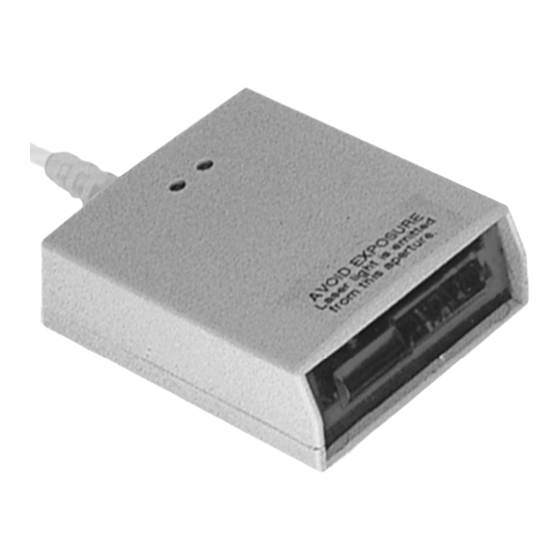
ARTS OF THE CANNER Figure 1. Scanner Parts Item Description Green LED When a bar code is read successfully the green LED will flash. Red LED When the red LED is illuminated, the laser is on. Red Output Window (Laser Aperture) Infrared Sensor (IR) If a specified time has elapsed without any scanning, the unit will enter a “standby”... -
Page 9: Visual Indicators
ISUAL NDICATORS There is a red and a green LED located on the top of the scanner. When the scanner is on, the flashing or constant illumination of the LEDs indicates the status of the current scan and the scanner. No Red LED Illumination of the LEDs will not occur if the scanner has remained dormant for a specified time and the scanner is... - Page 10 IGNAUX PTIQUES Sur la partie supérieure du scanner se trouvent une diode LED rouge et une diode LED verte. Quand le scanner est sous tension, les diodes rouge et verte clignotantes ou allumées vous informent sur l'état de palpage et de scanner. Ni la diode Il existe deux raisons possibles pour que les diodes ne rouge, ni la...
- Page 11 PTISCHE NZEIGEN Auf der Oberseite des Scanners befinden sich eine rote und eine grüne Leuchtdiodenanzeige. Ist der Scanner eingeschaltet, so geben Ihnen die blinkenden oder feststehenden Leuchtdiodenanzeigen Aufschluß über den Abtast und Scannerstatus. Es gibt zwei mögliche Gründe, weshalb die Leuchtdiodenan Weder rote zeigen nicht aufleuchten.
- Page 12 EGNALI TTICI Sulla parte superiore dello scanner si trovano due diodi luminosi: uno rosso e uno verde. Quando lo scanner è inserito, i diodi luminosi, che possono o essere accesi in continuazione o lampeggiare, Vi informano sullo stato della scansione e dell’apparecchio.
-
Page 13: Audible Indicators
UDIBLE NDICATORS The scanner provides sounds to signal certain conditions. To change the volume (four settings are available) or turn the beeper off, refer to Scanner Options: Beeper Options in the MetroSelect Single-Line Configuration Guide ( MLPN 02544). One Beep When the scanner first receives power, the red LED will flash, followed by the green LED, and then the scanner will beep once. -
Page 14: Labels
ABELS Each IS4225 has a serial number label and a laser class label on the bottom of the unit. These labels provide important information like; date and location of manufacture, model number, serial number, caution statements and laser class. There is also text molded into the top of the case near the window that says, “AVOID EXPOSURE - laser light emitted from this aperture”. -
Page 15: Infrared (Ir) Object Sensor
(IR) O NFRARED BJECT ENSOR An infrared (IR) device located behind the window initiates the scanning process. The IR sensor is active as long as power is applied to the unit. When the IR sensor detects an object, the green LED will flash. When the laser decodes a bar code, the scanner transmits the data to the host system and emits a beep to show that decoding is complete. -
Page 16: Scan Field
Scan Field The depth of field for the scanner is 12.7 mm to 203 mm (.5" to 8") from the face of the output window for .33 (13 mil) Bar Codes. Figure 3. Scan Field for .33 (13 mil) Bar Codes Specifications are subject to change without notice. -
Page 17: Specifications
Single scan line Min Bar Width: 0.173 mm (6.8 mil) Autodiscriminates all standard bar codes; for other Decode Capability: symbologies call a Metrologic representative RS232, Light Pen Emulation, PC Keyboard Wedge, Stand System Interfaces: Alone Keyboard, USB (low speed) Print Contrast:... -
Page 18: Default Settings
EFAULT ETTINGS Many functions of the scanner can be "configured", that is enabled or disabled. The scanner is shipped from the factory configured to a set of default conditions. All factory default parameters have an asterisk ( * ) in the default column of the charts on the following pages . - Page 19 EFAULT ETTINGS IGHT EYBOARD RS232 ARAMETER EFAULT EDGE ACK/NAK XON/XOFF No Intercharacter Delay 1 Millisecond Intercharacter Delay 5 Millisecond Intercharacter Delay 10 Millisecond Intercharacter Delay 25 Millisecond Intercharacter Delay 100 Millisecond Intercharacter Delay DTR Input DTR Scan Disable “DE” Disable Command LRC Calc+ Transmit RS232 Start LRC on first RS232 Byte Start LRC on Second RS232 Byte...
- Page 20 EFAULT ETTINGS IGHT EYBOARD RS232 ARAMETER EFAULT EDGE RSS Limited ID “]e0” RSS Limited App ID “01” RSS Limited Check Digit Full ASCII code 39 Code 39 Codabar Code 128 Code 93 Interleaved 2 of 5 (ITF) Code 11 Hong Kong Matrix 2 of 5 Airline 2 of 5 Minimum 1 Character Code Length Minimum 3 Character Code Length...
- Page 21 EFAULT ETTINGS IGHT EYBOARD RS232 ARAMETER EFAULT EDGE Mod 43 Check Digit Code 39 Transmit Mod 43 Check Digit Code 39 Transmit Start/Stop Code 39 CLSI Editing (Enable) ITF Check Digit Transmit MOD 10 ITF Check Digit I 2 of 5 Symbol Lengths Variable ISBN Reformatting Coupon Code 128...
- Page 22 EFAULT ETTINGS IGHT EYBOARD RS232 ARAMETER EFAULT EDGE BIO DATA Mode Golden Bountiful Formatting Intermec Polling Mode D (limited function) Enable Sineko Mode Enable Caps Lock Mode (for MI951 keyboard wedge) Enable French Wyse 120 PC Term Rochford Tompson Mode RTS Counter Toggle Beep on BEL RS232 Bancorner Mode...
-
Page 23: Troubleshooting Guide
800 Microsecond Delay-Enter Scan Code 15 Millisecond Delay-Enter Scan Code 7-5 Millisecond Delay-Enter Scan Code ROUBLESHOOTING UIDE The following guide is for reference purposes only. Contact a Metrologic representative at 1-800-ID-METRO or 1-800-436-3876 to preserve the limited warranty terms on page 20. YMPTOMS OSSIBLE... -
Page 24: Limited Warranty
Metrologic Customer Service/Repair Department to obtain a Returned Material Authorization (RMA) number. In the event that it is determined the equipment failure is covered under this warranty, Metrologic shall, at its sole option, repair the Product or replace the Product with a functionally equivalent unit... -
Page 25: Notices
OTICES Notice This equipment has been tested and found to comply with limits for a Class A digital device, pursuant to part 15 of the FCC Rules. These limits are designed to provide reasonable protection against harmful interference when the equipment is operated in a commercial environment. This equipment generates, uses and can radiate radio frequency energy and, if not installed and used in accordance with the instruction manual, may cause harmful interference to radio communications. - Page 26 OTICES European Standard Warning This is a class A product. In a domestic environment this product may cause radio interference in which case the user may be required to take adequate measures. Funkstöreigenschaften nach EN 55022:1998 Warnung! Dies ist eine Einrichtung der Klasse A. Diese Einrichtung kann im Wohnbereich Funkstörungen verursachen;...
-
Page 27: Patents
ATENTS This METROLOGIC product may be covered by one or more of the following U.S. Patents: U.S. Patent No. 5,260,553; 5,340,971; 5,340,973; 5,424,525; 5,468,951; 5,484,992; 5,525,789; 5,528,024; 5,627,359; 5,661,292; 5,742,043; 5,756,982; 5,777,315; 5,789,730; 5,789,731; 5,825,012; 5,874,721; 5,886,337; 5,925,870; 5,925,871; 5,984,187; 6,029,894; 6,085,981;... -
Page 28: Index
NDEX installation ........1 interfaces ........1 application ........1 audible........5–9 autodiscriminates......13 keyboard wedge..1, 13, 14–19 bar code ....4, 5–9, 10, 11, 19 labels........... 10 beep ......5–9, 13, 14, 19 LED..... 4, 5–9, 11, 13, 19 light levels ........13 light pen emulation .. - Page 29 NDEX roll, pitch, yaw......13 test code ........19 RS232 ......13, 14–19 tones ........9, 13 troubleshooting ......19 scan field ....... 5–9, 11, 12 scan pattern.........13 USB ........14–19 scan speed ......1, 13 USB keyboard emulation .... 19 serial number.......10 shock ...........13 short range activation ..
- Page 32 April 2006 Printed in the USA 0 0 - 0 2 2 5 8 B...
Need help?
Do you have a question about the IS4225 ScanGlove and is the answer not in the manual?
Questions and answers