
Related Manuals for Metrologic MK2320KD-60B241 - Metrologic MS 2320 Stratos H


Summary of Contents for Metrologic MK2320KD-60B241 - Metrologic MS 2320 Stratos H
- Page 1 METROLOGIC INSTRUMENTS, INC. ™ MS2320 Stratos H Scanner / Diva Scale Installation and User’s Guide...
- Page 2 Copyright © 2006 by Metrologic Instruments, Inc. All rights reserved. No part of this work may be reproduced, transmitted, or stored in any form or by any means without prior written consent, except by reviewer, who may quote brief passages in a review, or provided for in the Copyright Act of 1976.
-
Page 3: Table Of Contents
ABLE OF ONTENTS NTRODUCTION Manual Scope ..................................1 Product Overview..................................1 Base Kit Components................................2 Optional Accessories................................2 Replacement Parts................................... 4 General Precautions................................. 5 MS2320 Scanner/Diva Scale Design Specifications ........................ 6 ODEL HARACTERISTICS MS2320 Scanner/Diva Scale ..............................7 Components..................................7 Dimensions .................................. - Page 4 ABLE OF ONTENTS IBM 46xx .................................... 21 OCIA ....................................23 Cable Installation (Secondary Metrologic Scanner) ....................... 25 EAS Deactivation ................................... 27 CANNER PERATION Scan Zone....................................28 IR Activation Area (IR LED Output) ............................30 Indicator Descriptions................................31 Audible ....................................31 Visual ....................................
- Page 5 ABLE OF ONTENTS AINTENANCE Platter / Horizontal Scan Window Replacement........................52 Vertical Scan Window Replacement ............................53 Daily Maintenance.................................. 53 ROUBLESHOOTING Troubleshooting Symptom / Solution Chart..........................54 RS232 Demonstration Program ............................. 56 EFAULT ETTINGS Communication Parameters..............................57 CANNER AND ABLE ERMINATIONS Scanner Pinout Connections..............................
-
Page 7: Introduction
NTRODUCTION ANUAL COPE This guide provides information on the installation, setup and operation of Metrologic’s StratosH, MS2320 scanner/Diva scale unit. It is designed to be used in conjunction with Metrologic’s MetroSelect Configuration Guide ( 00-02407x) and the MLPN MS2x20 Stratos Series Scanner/Diva Scale Configuration Addendum ( 00-02272x). -
Page 8: Base Kit Components
NTRODUCTION OMPONENTS OMPONENTS Part # Description MS2 3 2 0 - x x K z StratosH™ Scanner / Diva Scale OCIA / RS232 Interfaces IBM46xx / RS232 Interfaces RS232 Interface Full Speed USB / RS232 Interfaces Diamonex Horizontal Window Sapphire Horizontal Window ®... -
Page 9: Optional Remote Scale Display
NTRODUCTION PTIONAL CCESSORIES Part # Description AC to DC Power Transformer - Regulated Output: +5V @ 1.5A +12V @ 1.5A 46-46812 120V United States and Canada 46-46813 220V – 240V Continental European 46-46814 220V – 240V United Kingdom 46-46817 220V – 240V China 46-46928 220V –... -
Page 10: Replacement Parts
NTRODUCTION EPLACEMENT ARTS EPLACEMENT ARTS Part # Description Window types (Diamonex and Sapphire) are not interchangeable due to laser safety and/or scanner performance differences. Caution To change window type, the scanner must be returned to the manufacturer for reconfiguration. 46-46889 Vertical Window 46-46806 Diamonex Platter –... -
Page 11: General Precautions
NTRODUCTION ENERAL RECAUTIONS The following list includes general precautions to remember when handling the StratosH. the unit upside down with the platter in place. Figure 3 on the window in the RESS placement platter or the vertical window frame. Figure 4 LATTER EMOVAL No hardware or tools are required to remove the... -
Page 12: Ms2320 Scanner/Diva Scale Design Specifications
NTRODUCTION MS2320 S CANNER CALE ESIGN PECIFICATIONS Design Specifications Operational Light Source: VLD 650 nm Peak Laser Power: <2.2 mW Maximum IR LED Output: 50μW per IEC 60825-1 measurement procedure Horizontal Depth of Field: 0 mm - 152 mm (0”- 6”) for 0.33 mm (13 mil) Bar Code Vertical Depth of Field: 0 mm - 216 mm (0”- 8.5”) for 0.33 mm (13 mil) Bar Code Scan Speed:... -
Page 13: Base Model Characteristics
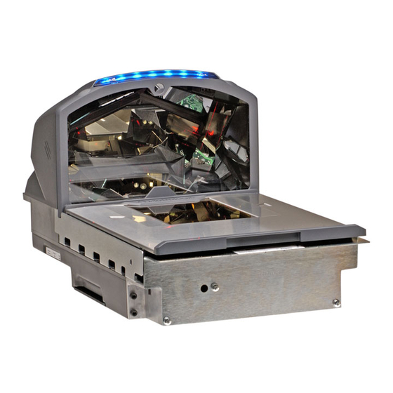
ODEL HARACTERISTICS MS2320 Scanner/Diva Scale Components Figure 7. MS2320 Components ESCRIPTION OF Blue and White LED Indicators (see page 31) Volume/Tone Multi-Function Button (see page 36) Scale Zero Button Speaker (see page 31) High Impact Window Frame / Vertical Window (Laser Aperture) (see page 4) Flow Direction Indicators Platter with Finger Recess, Stainless Steel Option Not Shown (see page 4) Diamonex or Sapphire (shown) Horizontal Window (Laser Aperture) -
Page 14: Dimensions
ODEL HARACTERISTICS MS2320 Scanner/Diva Scale Dimensions Figure 8. MS2320 Dimensions Connector Panel Figure 9. MS2320 Connector Panel Specifications are subject to change without notice. -
Page 15: Caution And Serial Number Labels
ODEL HARACTERISTICS MS2320 Scanner/Diva Scale Caution and Serial Number Labels Figure 10. MS2320 Label Locations (Top) and Examples (Bottom) Caution: To maintain compliance with applicable standards, all circuits connected to the scanner must meet the requirements for SELV (Safety Extra Low Voltage) according to EN/IEC 60950-1. To maintain compliance with standard CSA C22.2 No. -
Page 16: Installation
NSTALLATION UICK NSTALLATION UTLINE The following is a quick preview of the steps required for 1 time installations. Each item is discussed in detail later in this section. • Determine clearance, ventilation and service access requirements. • Determine checkout counter layout taking into account package flow, cable routing and power requirements. •... -
Page 17: Power Installation
NSTALLATION UICK NSTALLATION UTLINE OWER NSTALLATION The Power Supply (AC/DC) should be connected to an AC Outlet that is free of electrical noise (clean). A qualified electrician can determine the amount of electrical noise on the AC line. See additional information on power installation and restrictions under the Installation: Cable Installation (Interface Specific) section of this manual. -
Page 18: Unpacking The Unit
NSTALLATION NPACKING THE Make sure the shipping box is top-side up before opening. Remove the accessories box and check the box’s content for the following items. • Product Manuals • Power Supply • Communication Cables • Remote Scale Display Pole (Optional) Figure 11 Carefully remove the platter and store it in a safe location until the unit is properly installed into the checkout counter. -
Page 19: Ms2320 Package Warning
NSTALLATION NPACKING THE MS2320 Package Warning There is a protective film located on the topside platter surface, vertical scan windows outer surface, and the horizontal scan windows top surface. This film must be removed prior to performing any scanner operation (see Figure 15). All foam wedges securing the scale arms during shipping must be removed or the scale will not function (see Figure 15)! Figure 15. -
Page 20: Ms2320 Mounting Diagram (Two Point Support)
NSTALLATION NSTALLING THE NIT IN THE OUNTER MS2320 Mounting Diagram (Two Point Support) Figure 18. MS2320 Mounting Diagram, Two Point Support Specifications are subject to change without notice. -
Page 21: Ms2320 Mounting Diagram (Three Point Support)
NSTALLATION NSTALLING THE NIT IN THE OUNTER MS2320 Mounting Diagram (Three Point Support) Figure 19. MS2320 Mounting Diagram, Three Point Support Specifications are subject to change without notice. -
Page 22: Cable Installation (Interface Specific)
NSTALLATION ABLE NSTALLATION NTERFACE PECIFIC RS232 The following steps describe how to properly install the cables for an RS232 StratosH application. The scanner/Diva scale must then be configured to match the host’s RS232 parameters. Cable installation alone does not guarantee that the StratosH will communicate properly with the host system. - Page 23 NSTALLATION ABLE NSTALLATION NTERFACE PECIFIC RS232 Turn on the host system. 10. Scan the Recall Defaults bar code. The Recall Defaults bar code is located in the MetroSelect Configuration Guide ( 00-02407x), under MLPN Need to Start Over. 11. Configure the StratosH to match the host system’s RS232 parameters. Refer to the MetroSelect Configuration Guide ( 00-02407x) under Section G: RS232 for Enabling RS232 MLPN...
-
Page 24: Full Speed Usb
NSTALLATION ABLE NSTALLATION NTERFACE PECIFIC PEED The following steps describe how to properly install the cables for a Full Speed USB StratosH application. The scanner/scale must then be configured to match the host’s USB parameters. Cable installation alone does not guarantee that the StratosH will communicate properly with the host system. -
Page 25: Ibm Oem
NSTALLATION ABLE NSTALLATION NTERFACE PECIFIC PEED Turn on the host system. 10. Configure the StratosH to match the host system’s USB parameters. For Single Cable Applications: The IBM OEM Full Speed USB English and Metric bar codes are located in the MS2 20 Stratos Series Scanner/Diva Scale Configuration Addendum ( 00-02272... - Page 26 NSTALLATION ABLE NSTALLATION NTERFACE PECIFIC xxx* Specifies international connection. See page 3 for a complete listing of power supply options and their part numbers. See page 3 for information on optional display types and part numbers. See power source caution statement on page 9 of this manual. Figure 21.
-
Page 27: Ibm 46Xx
NSTALLATION ABLE NSTALLATION NTERFACE PECIFIC IBM 46 The following steps describe how to properly install the cables for an IBM 46xx StratosH application. The scanner/scale must then be configured to match the host’s IBM 46xx parameters. Cable installation alone does not guarantee that the StratosH will communicate properly with the host system. - Page 28 NSTALLATION ABLE NSTALLATION NTERFACE PECIFIC IBM 46 Turn on the host system. 10. Configure the StratosH to match the host system’s IBM 46xx parameters. For Single Cable Applications: The IBM 3 Generation 46xx, English and Metric bar codes are located in the MS2 20 Stratos Series Scanner/Diva Scale Configuration Addendum ( 00-02272...
-
Page 29: Ocia
NSTALLATION ABLE NSTALLATION NTERFACE PECIFIC OCIA The following steps describe how to properly install the cables for an OCIA StratosH application. The scanner/scale must then be configured to match the host’s OCIA parameters. Cable installation alone does not guarantee that the StratosH will communicate properly with the host system. - Page 30 NSTALLATION ABLE NSTALLATION NTERFACE PECIFIC OCIA Connect AC power to the transformer. If the AC outlet is equipped with an on/off switch, turn the power on. Turn on the host system. 10. Configure the StratosH to match the host system’s OCIA parameters. Refer to the MetroSelect Configuration Guide ( 00-02407x) under Section I: OCIA for Enabling and MLPN...
-
Page 31: Cable Installation (Secondary Metrologic Scanner)
NSTALLATION ABLE NSTALLATION ECONDARY ETROLOGIC CANNER The following steps describe how to properly install the cables between a secondary Metrologic scanner and the StratosH. The StratosH and the secondary scanner must then be configured to communicate properly. Cable installation alone does not guarantee that the StratosH will communicate properly with the host system and secondary scanner. - Page 32 NSTALLATION ABLE NSTALLATION ECONDARY ETROLOGIC CANNER † See Aux power notes on page 25 See power source caution statement on page 9 of this manual. Figure 24. Secondary Scanner Cable Installation Schematic...
-
Page 33: Eas Deactivation
NSTALLATION EAS D EACTIVATION SW1 and SW2 are the switch banks inside the Checkpoint device that set the deactivation range. The following is a list of Checkpoint recommended switch bank settings. Base Model Checkpoint Recommended Switch Bank Settings MS2320 SW1 & SW2 switches 1 and 6 set to ON All StratosH models have a connector labeled EAS In on the bottom of the unit. -
Page 34: Scanner Operation
CANNER PERATION Figure 27. Checker-Side (13 mil) Figure 28. Horizontal Left/Right (13 mil) Specifications are subject to change without notice. - Page 35 CANNER PERATION Figure 29. Horizontal Direct (13 mil) Figure 30. Vertical Direct (13 mil) Specifications are subject to change without notice.
-
Page 36: Ir Activation Area (Ir Led Output)
CANNER PERATION IR A (IR LED O CTIVATION UTPUT † † The StratosH’s default power save mode is Dual Action Power Save Mode #2 (see page 35). This power save mode turns the laser OFF after a configured period of non-use then turns the motor OFF after thirty-minute intervals. Any movement detected by the IR in the activation area, shown below, will cause the scanner to exit the power save mode. -
Page 37: Indicator Descriptions
CANNER PERATION NDICATOR ESCRIPTIONS Audible When in operation the StratosH provides audible feedback that indicates the status of the unit and the current scan. Eight settings are available for the tone of the beep (normal, 6 alternate tones and no tone) plus three volume settings. To change the tone or volume, refer to the Changing the Beeper Tone &... -
Page 38: Failure
CANNER PERATION NDICATOR ESCRIPTIONS Visual Steady White and Blue After a successful scan, the scanner transmits the data to the host device. Some communication modes require that the host inform the scanner when data is ready to be received. If the host is not ready to accept the information, the scanner’s white LED will remain on until the data can be transmitted. -
Page 39: Diagnostic Indicator Display; Error Codes
CANNER PERATION NDICATOR ESCRIPTIONS Diagnostic Indicator Display There is a two-digit error code display located under the platter near the end of the scanner farthest from the vertical window (see figure below). Figure 33. Error Code Display The following is a list of possible error codes and their meanings. Some errors will require immediate scanner maintenance. RROR ESCRIPTION Reserved... - Page 40 CANNER PERATION NDICATOR ESCRIPTIONS Diagnostic Indicator Display RROR ESCRIPTION SWITCH ERROR – The switch used for volume selection or sleep mode is detected in error (always closed). The condition is self-correcting if possible. If the error persists, return the unit for repair at an authorized service center. The scanning operation can continue with this error active.
-
Page 41: Power Save Modes
CANNER PERATION OWER ODES The StratosH has five configurable power save modes. Refer to the MetroSelect Configuration Guide ( 00-02407 MLPN for additional information on Power Save Modes. Blink Power Save Mode: Blinks the laser OFF & ON after a configured period of non-use. When the scanner recognizes a bar code it will exit the Blink mode. -
Page 42: Beeper Options And Button Functions
CANNER PERATION EEPER PTIONS AND UTTON UNCTIONS Changing the Beeper Tone Beeper tones may be configured incrementally using the following bar code. The new tone will be heard followed by a short pause. Two more new tones will be heard signifying the new setting has been stored in memory. The silent (no beep) tone is also selectable. -
Page 43: Startup
CANNER PERATION TARTUP When the scanner first receives power the white LED will flash, the blue LED will turn on and the scanner will beep once (the white LED will remain on for the duration of the beep). The scanner is now ready to scan. OWER When a StratosH scanner is first powered up, it cycles through a number of self-tests before starting normal operation. -
Page 44: Scale Operation
CALE PERATION CALE EROING After the unit has been officially calibrated (see page 39) the scale can be re-zeroed by pressing the scale zeroing button on either the unit or on the remote display stand. Refer to the figures below for button locations. Figure 38. -
Page 45: Calibration
CALE PERATION ALIBRATION The scanner/scale must be calibrated if: • it is a first time installation • the scale cannot be re-zeroed • the calibration verification tests indicate errors • there is a change in the units of measure [i.e. from pounds (lbs.) to kilograms (kg)] •... -
Page 46: Priming The Scale For Calibration (Lbs. & Kg)
CALE PERATION ALIBRATION Priming the Scale for Calibration Prime the scale before starting either method of calibration. Calibrate the scanner/scale after the unit is installed in the checkout countertop. It is important to use the correct certified (lb. or kg.) field weight set when calibrating the scale. Check the platter to ensure that nothing is interfering with its freedom to move. -
Page 47: Scale Calibration Procedure (Lbs. & Kg) With Remote Display
CALE PERATION ALIBRATION Scale Calibration Procedure (lbs. or kg) with Remote Display* Temporarily remove the platter and place it in a safe location. It is the responsibility of the owner of the scale to confirm compliance with the relevant Weights and Measures statutes and regulations applicable in your area by checking with the appropriate government agency before placing a newly calibrated unit into service or removing any official seals. - Page 48 CALE PERATION ALIBRATION Scale Calibration Procedure (lbs. or kg) with Remote Display* Reinstall the platter onto the scanner/scale. Figure 45. Install Platter Go to Group 1 Step 8 (Weight Unit) of the Service Mode by pressing the Zero ( ) key several times until ‘Group 1 Step 8’...
- Page 49 CALE PERATION ALIBRATION Scale Calibration Procedure (lbs. or kg) with Remote Display * Go to Group 2 Step 6 (Calibration) of the Service Mode. Press the Tare ( ) key to advance to Group 2, then use the Zero ( ) key to advance to step 6 of group 2.
-
Page 50: Bar Code Calibration Procedure Without Remote Display
CALE PERATION ALIBRATION Bar Code Calibration Procedure without Remote Display* The following calibration procedure can be used when the remote scale display is not present. The Multi-Function Button (see page 36) is used to advance to the next stage of calibration and the LED display notifies the operator which ‘calibration stage’... - Page 51 CALE PERATION ALIBRATION Bar Code Calibration Procedure without Remote Display* Reinstall the platter onto the scanner/scale (see Figure 49). Figure 49. Platter Installation Enter bar code calibration mode. Use the vertical window to scan one of the following bar codes, whichever weight units (either pounds or kilograms) the scanner/scale will be operating in.
- Page 52 CALE PERATION ALIBRATION Bar Code Calibration Procedure without Remote Display* Unit Calibration (Kilograms) For Pound weight units see instructions on page 45. Kilograms Calibration ³ Figure 51. Entering Bar Code Calibration Mode (Kilograms) If a razz tone sounds, an error has occurred. Refer to Diagnostic Indicator Display; Error Codes starting on page 33 for additional information.
- Page 53 CALE PERATION ALIBRATION Bar Code Calibration Procedure without Remote Display* Make sure there is no load on the scale platter. The white LEDs will be used to indicate the current step in the calibration process. Calibrate a zero load. The white LEDs will blink once periodically. Wait 8 to 10 seconds for scale stability, and then press the Multi-Function Button once.
-
Page 54: Calibration Verification
CALE PERATION ALIBRATION ERIFICATION U.S. Pounds (lbs.) The following tests verify if the scale's Calibration is accurate. For Kilograms see instructions starting on page 49. The following tests are based on a 2-digit accuracy setting for pounds. Increasing Load Test Shift Test Decreasing Load Test Return to Zero Test... -
Page 55: Kilograms (Kg)
CALE PERATION ALIBRATION ERIFICATION Kilograms (kg) The following tests verify if the scale's Calibration is accurate. For US Pounds see instructions starting on page 48. The following tests are based on a 3-digit accuracy setting for kilograms. Increasing Load Test Shift Test Decreasing Load Test Return to Zero Test... -
Page 56: Security Seal Installation
CALE PERATION ECURITY NSTALLATION The certification of the weighing mechanism of the scale version of this scanner is subject to federal, state and local Weights and Measures statutes and regulations and can only be performed by authorized government agencies and/or their duly registered agents. Each time the scale or weighing mechanism is calibrated, it should be properly sealed with a paper seal or a wire seal prior to being placed into service in commerce. -
Page 57: Wire Security Seal (Conversion Kit 46-00359)
CALE PERATION ECURITY NSTALLATION Wire Security Seal (Seal Conversion Kit 46-00359)* MLPN Temporarily remove the platter and place it in a safe location. Install the calibration button sealing cover and through-hole sealing screw. Tighten the screw and route the wire seal through the holes in the plate and screw. Figure 60. -
Page 58: Maintenance
AINTENANCE LATTER ORIZONTAL INDOW EPLACEMENT Figure 62. Platter/Horizontal Scan Window Replacement* * See replacement parts on page 4. -
Page 59: Vertical Scan Window Replacement
AINTENANCE 46-46889) ERTICAL INDOW EPLACEMENT MLPN Figure 63. Vertical Scan Window Replacement AILY AINTENANCE Smudges and dirt can interfere with the proper scanning of a bar code. Therefore, the horizontal and vertical output windows will need occasional cleaning. For the glass window: Spray glass cleaner onto lint free, non-abrasive cleaning cloth. -
Page 60: Troubleshooting
ROUBLESHOOTING The following guide is for reference purposes only. Contact a Metrologic representative at 1-800-ID-METRO or 1-800-436-3876 to preserve the limited warranty terms. Symptom Possible Cause(s) Solution All Interfaces No LEDs, beep or motor No power is being supplied Check the transformer, outlet and the power strip. Make sure spin. - Page 61 ROUBLESHOOTING Symptom Possible Cause(s) Solution All Interfaces The print quality of the bar code is suspect. The type of printer and/or the printer settings could be the problem. Check the character length lock. Check the print mode or change the printer settings. For example change to econo mode or high speed.
-
Page 62: Rs232 Demonstration Program
ROUBLESHOOTING RS232 D EMONSTRATION ROGRAM If an RS232 scanner is not communicating with your IBM compatible PC, key in the following BASIC program to test that the communication port and scanner are working. This program is for demonstration purposes only. It is only intended to prove that cabling is correct, the com port is working, and the scanner is working. -
Page 63: Default Settings
EFAULT ETTINGS OMMUNICATION ARAMETERS Many functions of the scanner can be "configured" - that is, enabled or disabled. The scanner is shipped from the factory pre- configured to a set of default conditions. The default parameter of the scanner has an asterisk ( * ) in the charts on the following pages. - Page 64 EFAULT ETTINGS OMMUNICATION ARAMETERS OCIA RS232 IBM 46 ARAMETER EFAULT RSS Expanded Enable Expanded ID “]e0” RSS Limited Enable RSS Limited ID “]e0” RSS Limited App ID “01” RSS Limited Check Digit DTS/SIEMENS DTS/NIXDORF NCR F NCR S Beeper Tone Normal Beep Transmit Sequence Before Transmit...
- Page 65 EFAULT ETTINGS OMMUNICATION ARAMETERS OCIA RS232 IBM 46 ARAMETER EFAULT Dual Action Power Save Mode #2 Same Symbol Rescan Timeout: 500 msecs Configurable in 500 msec 50 msec steps (MAX 6.35 seconds) Intercharacter Delay Configurable in 1 msecs 1 msec steps (MAX 255 msecs) 10 msecs in KBW Number of Scan Buffers UPC GTIN-14 Format...
- Page 66 EFAULT ETTINGS OMMUNICATION ARAMETERS OCIA RS232 IBM 46 ARAMETER EFAULT EAN 128 Enable Enable French Pharma Enable Matrix 2 of 5 Check Digit Enable Hong Kong 2 of 5 Enable Alpha Telepen Telepen Convert Lead ‘^L’ to ‘E’ Enable Code 11 Check Digit Parity Space Baud Rate...
- Page 67 EFAULT ETTINGS OMMUNICATION ARAMETERS OCIA RS232 IBM 46 ARAMETER EFAULT STX Prefix TAB Prefix Metrologic Prefix UPC Prefix ETX Suffix TAB Suffix Carriage Return Suffix Line Feed Suffix UPC Suffix Transmit LRC Start LRC on 1 Byte Start LRC on 2 Byte ‘c’...
- Page 68 EFAULT ETTINGS OMMUNICATION ARAMETERS OCIA RS232 IBM 46 ARAMETER EFAULT Five Digit Redundancy Enable Coupon Code 128 Transmit Coupon ‘]C1’ Group Separator Coupon Code Can Begin with ’4’ Enable EAN-99 Coupon Code Bookland Supplements French 378/379 Supplements German 434/439 Supplements Convert Bookland to ISBN Bookland 979 Supplements Convert 979 to ISBN...
- Page 69 EFAULT ETTINGS OMMUNICATION ARAMETERS Default settings for “Aux” interface The secondary scanner and the StratosH series always communicates via RS232. Data is relayed to the host via various primary interfaces OCIA RS232 IBM 46 ARAMETER EFAULT Aux Baud Rate 38400 Aux Parity none Aux Data Bits...
-
Page 70: Scanner And Cable Terminations
CANNER AND ABLE ERMINATIONS CANNER INOUT ONNECTIONS The StratosH scanner terminates to 10-pin modular jacks located on the bottom of the unit. The serial number label indicates the model number and interface of the scanner. EAS In Auxiliary RS232 In Function Function EAS In... - Page 71 CANNER AND ABLE ERMINATIONS CANNER INOUT ONNECTIONS Figure 65. Scale Data (Dual Cable Applications) and Scale Display Connector Layout Scale RS232 to Host Scale to Display Scale Data, Dual Cable Applications Function Function Ground SIG1 Scale RS232 TX Out SIG2 Scale RS232 RX In SIG3 Scale RS232 RTS Out...
-
Page 72: Cable Connector Configurations
CANNER AND ABLE ERMINATIONS ABLE ONNECTOR ONFIGURATIONS The following cables are examples of some of the standard cables that may be shipped with the StratosH scanner. Please keep in mind that every application is unique and the cables received with the StratosH may be custom cables that are not shown below. - Page 73 CANNER AND ABLE ERMINATIONS ABLE ONNECTOR ONFIGURATIONS Aux Port Configuration Cable*, 57-57008x-N-3 MLPN Function No Connect Output from Scanner Input to Scanner No Connect Ground 9-Pin D-Type Connector No Connect RS232 LSO/AUX Cable, 57-57099x -3 MLPN † Function Signal Ground RS232 from Aux / Secondary Scanner RS232 to Aux / Secondary Scanner RTS from Aux / Secondary Scanner...
-
Page 74: Regulatory Compliance
EGULATORY OMPLIANCE AFETY ITE Equipment IEC 60950-1; EN 60950-1 Laser Laser Class 1: IEC 60825-1:1993+A1+A2, EN: 60825-1:1994+A1+A2 Caution Use of controls or adjustments or performance of procedures other than those specified herein may result in hazardous laser light exposure. Under no circumstances should the customer attempt to service the laser scanner. Never attempt to look at the laser beam, even if the scanner appears to be nonfunctional. -
Page 75: Emc
EGULATORY OMPLIANCE Emissions: FCC Part 15, ICES-003, CISPR 22, EN 55022 Immunity: CISPR 24, EN 55024 Class A Devices The following is applicable when the scanner cable is greater in length than 3 meters (9.8 feet) when fully extended: Les instructions ci-dessous s’appliquent aux cables de scanner dépassant 3 métres (9.8 pieds) de long en extension maximale: Folgendes trifft zu, wenn das Scannerkabel länger als 3 Meter ist: This equipment has been tested and found to comply with limits for a Class A digital device, pursuant to part 15 of the FCC... -
Page 76: Weights & Measures
EGULATORY OMPLIANCE Class B Devices The following is applicable when the scanner cable is less than 3 meters (9.8 feet) in length when fully extended: Les instructions ci-dessous s’appliquent aux cables de scanner ne dépassant pas 3 métres (9.8 pieds) de long en extension maximale: Folgendes trifft zu, wenn das Scannerkabel kürzer als 3 Meter ist: This device complies with Part 15 of the FCC Rules. -
Page 77: Limited Warranty
IMITED ARRANTY The MS2320 StratosH™ Series scanners are manufactured by Metrologic at its Blackwood, New Jersey, U.S.A. facility. The MS2300 StratosH Series scanners have a two (2) year limited warranty from the date of manufacture. Metrologic warrants and represents that all MS2320 StratosH Series scanners are free of all defects in material, workmanship and design, and have been produced and labeled in compliance with all applicable U.S. -
Page 78: Patents
ATENTS Patent Information This METROLOGIC product may be covered by, but not limited to, one or more of the following U.S. Patents: U.S. Patent No.; 5,343,027; 5,627,359; 5,686,717; 5,789,731; 5,828,049; 6,029,894; 6,209,789; 6,299,065; 6,345,505; 6,422,467; 6,481,625; 6,494,377; 6,814,292; 6,830,190; 6,874,690; 6,918,540; 6,951,304; No license right or sublicense is granted, either expressly or by implication, estoppel, or otherwise, under any METROLOGIC or third party intellectual property rights (whether or not such third party rights are licensed to METROLOGIC), including any third party patent listed above, except for an implied license only for the normal intended use of the specific equipment,... -
Page 79: Index
NDEX AC ..............see power ground...............66–69 application ..............35, 58 audible............see indicators AUX...............9, 57, 66 handles .................5, 9 host ..........33, 34, 39, 56–58, 59–65 beep ..............see indicators blue LED ............see indicators IBM 46xx ..............59–65 button indicators................6 calibration .............42, 44 audible......33, 38, 39, 56–58, 60, 61, 62 display ................44 diagnostic .............35–36 multi-function ............9, 38... - Page 80 NDEX safety.................71, 72 unit of measure ............50, 51 scale................6, 12 USB................59–65 scan pattern ..............6 scan speed................6 scan zone..............30–31 ventilation ..............6, 12 scanner visual................34 pinouts..............66–69 voltage .............. 2, 6, 18–26 seal..............43, 46, 52 volume ................9, 38 secondary scanner ............27, 28 SELV .................18–26 specifications..............6–7 warranty ..............56, 73 storage ................6...
- Page 84 December 2006 (Version 1) Printed in the USA 0 0 - 0 2 2 7 1 A...
Need help?
Do you have a question about the MK2320KD-60B241 - Metrologic MS 2320 Stratos H and is the answer not in the manual?
Questions and answers